
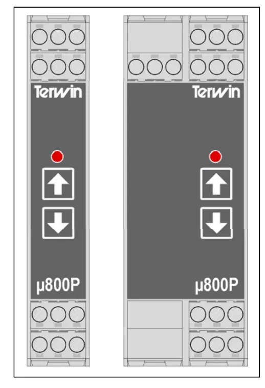
 TERWIN µ800P Power Supply / Signal Conditioner
 Isolated pressure tranducer/Signal Conditioner Model µ800P
 Isolated pressure tranducer/Signal Conditioner Model µ800P
You must read the instruction manual before starting up the equipment.
Wairing
The connections must be made with the instrument installed in its final place of operation. In order to prevent electrical discharges whilst making the connections, do no t connect the instrument to the relevant supply until after all other connections have been made.
It is advisable to be guided by the following recommendations wherever possible:
- Do not connect the instrument to the relevant supply until after all other connections have been made.
- Do not install the instrument near moving parts, contactors or motor starters.
- Endeavour to prevent mechanical vibrations.
- Do not wire the signal lines together with the power lines.
- For the signal lines, it is advisable to use a shielded wire with the earth connection at one single point.
- It is important to check the configuration of the instrument (inputs and outputs) in the event of any problems when starting operation.
Installation or use of the equipment other than specified in this manual may reduce the levels of protection provided in the equipment.
24V DC SUPPLY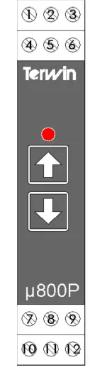
- CAL (1 of 2)
- Excitation negative (-) (0V)
- Excitation positive (+) (9V)
- CAL (2 of 2)
- Signal negative (-)
- Signal positive (+)
- Current output positive (+)
- Current output negative (-)
- Voltage output negative (-)
- Power supply positive (+) (24V)
- Power supply negative (-) (0V)
- Voltage output positive (+)
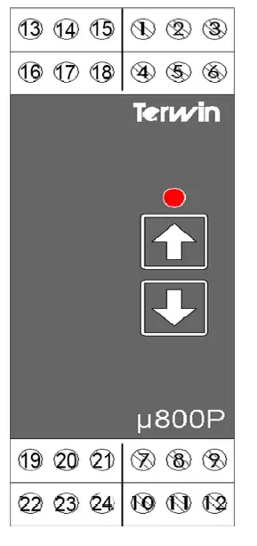
85 to 265V 50/60Hz Supply
- CAL (1 of 2)
- Excitation negative (-) (0V)
- Excitation positive (+) (9V)
- CAL (2 of 2)
- Signal negative (-)
- Signal positive (+)
- Current output positive (+)
- Current output negative (-)
- Voltage output negative (-)
- Voltage output positive (+)
- Power supply 85-265V 50/60Hz
- Power supply 85-265V 50/60Hz
OPERATION
Power on the device. During initialisation the LED will flash at a speed of 2 flashes per second. If everything is configured ok, the LED will stay on and the device will begin to work. After initialisation, should there be a hardware or configuration error the LED will flash at 5 flashes per second.
AUTO Zero & 80% TRANSDUCER CALIBRATION
To start the transducer calibration process, press the up button for 5 seconds. The LED will flash at 1 flash per second. During this process, the instrument will automatically calibrate the transducer zero and 80%. On each of these steps the output signal will be updated with 0 and 80% of full scale output. If no errors are encountered during the calibration, the LED will flash at a rate of 2 times per second and will wait for the user input to accept calibration. At this time, the output is updated using the new calibration values. If calibration is correct press the up button to save the calibration values. If down or no button is pressed for 15 seconds, the device will return to normal mode without saving new calibration values. If there are any errors during the calibration routine, the calibration LED will flash at a rate of 5 flashes per second.
NOTICE:
This manual is supplied as a guide only. All installations should be carried out by qualified personnel. Terwin Instruments cannot be held responsible for any errors or omissions contained within.
T:\Terwin Templates\Manuals\μ800P Manual\Terwin μ800P Instruction Manual (c).docx
©Terwin Instruments Ltd 2011
OUTPUT CONFIGURATION
The output signal type can be chosen by means of a set of switches located inside the circuit board. Please turn off the power supply, remove the circuit from its enclosure and select the switches according to the table below. After selecting the switches in the desired position, the instrument must be powered up again.
To setup the device, power up and press both up and down buttons for 5 seconds. The led will flash from 1 to 4 times in 1.5 second to show the present output configuration. Use up/down button to select the desired output value. Once selected press both up and down buttons for 2 seconds to save the selection. If no button is pressed for 15 seconds, the device will return to normal mode (note that switch 1 selects between current and voltage output, so there are only 4 options in menu selection)
| Switches ON | Output | Flashes (menu) |
| 1,4,6,8 | 0-1V | 1 |
| 1,6,8 | 1-5V | 2 |
| 1,6,8 | 0-5V | 3 |
| 1,5,8 | 0-10V | 4 |
| 2,7 | 0-20mA | 1 |
| 2,7 | 4-20mA | 2 |
| 7 | 0-1mA | 3 |
| 3,7 | 0-10mA | 4 |
TECHNICAL SPECIFICATIONS
| Power supply | 24V DC or 85-265VAC (depending on the model ordered) | ||||
| Consumption | 4W | ||||
| Ambient Temp. | 0 to 50ºC | ||||
| Relative humidity | max. 80% without condensation | ||||
| Altitude | max. 2000 m | ||||
| Installation cat. | II according to EN61010-1 | ||||
| Pollution grade | I according to EN61010-1 | ||||
| Box | ABS self-extinguishable | ||||
| Dimensions | DC Supply Version | 17.5mm (w) x 99mm (h) x 115mm (d) | AC Supply Version | 35mm (w) x 99mm (h) x 115mm (d) | |
| Input | Pressure transducer 1.5 to 4mV/V | ||||
|
Minimum output change assuming correct output calibration | 0..1V 0..5V 1..5V 0..10V 0..1mA 0..10mA 0..20mA 4..20mA | 300 µV 300 µV 300 µV 300 µV 300 nA 300 nA 300 nA 300 nA | |||
| Analog output | User-selectable: 0 to 1V, 0 to 5V, 1 to 5V, 0 to 10V, 0 to 1mA, 0 to 10mA, 0 to 20mA, 4 to 20mA | ||||
| Power supply for pressure transducer (Excitation) | 9V DC ( max. 100mA ) | ||||
| Weight | DC Version | 105 grams | AC Supply Version | 185 grams | |
| CE Certification | Safety, EMI Susceptibility, EMI Emission, Harmonics, Voltage fluctuations | ||||
SERVICING
If repairs are required, the instrument should be adequately packed to prevent damage, with a note describing the observed problems and shipped pre-paid to your nearest Terwin representative or:-
WARRANTY
Terwin Instruments Limited warrants equipment of its manufacture against defects in materials and workmanship for a period of one year from date of despatch. Terwin Instruments Limited’s obligation under warranty is expressly limited to the repairing or replacing at its factory, or at any authorised representatives repair station, providing that:
- Terwin Instruments Limited is promptly notified by the buyer upon his/her discovery of a defect.
- The defective equipment is returned, with transportation charges pre-paid by the buyer.
- Providing the defective unit has not been damaged by negligence, improper use or unauthorised repair or alteration.
THIS WARRANTY IS IN LIEU OF ALL OTHER WARRANTIES, EXPRESSED OR IMPLIED, INCLUDING THE IMPLIED WARRANTY OF FITNESS FOR A PARTICULAR PURPOSE WHETHER TO THE ORIGINAL PURCHASER OR TO ANY OTHER PERSON. TERWIN INSTRUMENTS LIMITED SHALL NOT BE LIABLE FOR CONSEQUENTIAL DAMAGE OF ANY KIND.
The aforementioned provisions do not extend the original warranty period of any article that has been either repaired or replaced by Terwin Instruments Limited.
Terwin Instruments Limited shall not be bound by any terms, conditions, representations or warranties, expressed or implied, which are not stated herein.
NOTICE:
This manual is supplied as a guide only. All installations should be carried out by qualified personnel. Terwin Instruments cannot be held responsible for any errors or omissions contained within. T:\Terwin Templates\Manuals\µ800P Manual\Terwin µ800P Instruction Manual (c).docx
©Terwin Instruments Ltd 2011


