![]()

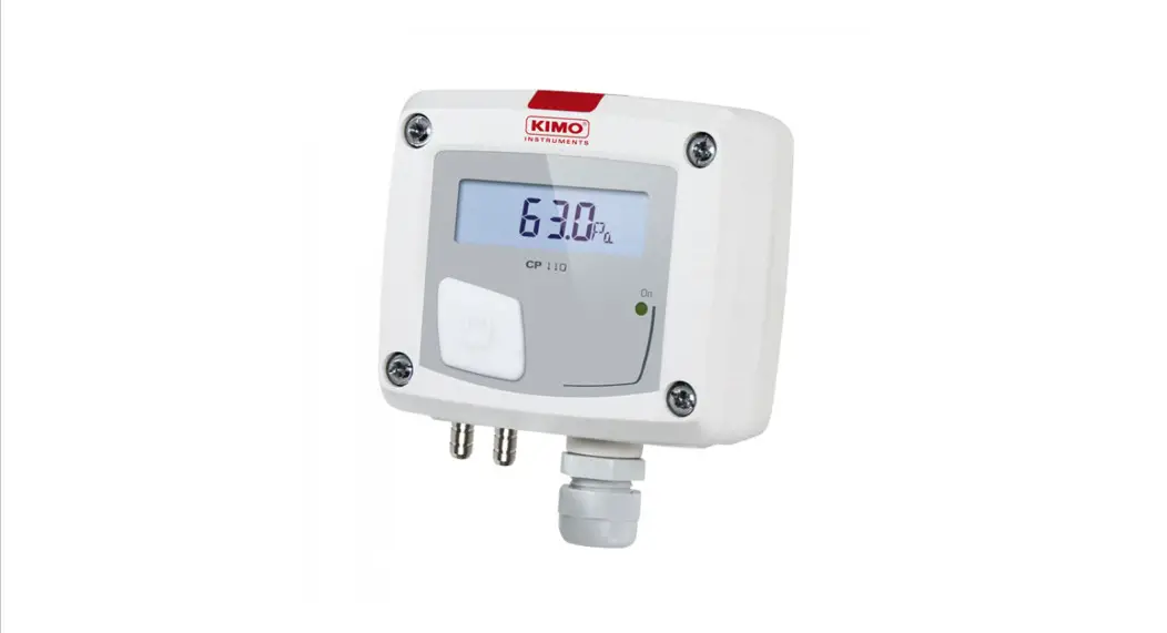
CP 110
Quick Start Guide
Quick Start Guide
Differential pressure transmitter![]() Ranges from -500/+500 Pa to -10 000/+10 000 Pa (according to model)
Ranges from -500/+500 Pa to -10 000/+10 000 Pa (according to model)![]() Configurable intermediary ranges
Configurable intermediary ranges
Features
- 0-10 V or 4-20 mA output, active, power supply 24 Vac/Vdc (3-4 wires) or 4-20 mA output, passive loop, power supply from 16 to 30 Vdc (2 wires)
- ABS V0 housing, IP65, with or without display
- “¼ turn” system mounting with wall-mount plate
- Housing with simplified mounting system
- Solenoid valve for auto-calibration (only on CP 111 model)
General features
| Output / Supply | Active sensor 0-10 V or 4-20 mA (alim. 24 Vac/Vdc ±10%), 3-4 wires Passive loop 4-20 mA (power supply 16/30 Vdc), 2 wires Common mode voltage <30 VAC Maximum load: 500 Ω (4-20 mA) / minimum load: 1 K Ω (0-10 V) |
| Consumption | CP 111: 3 VA (0-10 V) or 3 VA (4-20 mA) CP112, CP113, CP 114, CP 115: 2 VA (0-10 V) or 0.6 VA (4-20 mA) |
| European directives | 2014/30/EU EMC; 2014/35/EU Low Voltage; 2011/65/EU RoHS II; 2012/19/EU WEEE |
| Electrical connection | Screw terminal block for cables from 0.05 to 2.5 mm2 or from 30 to 14 AWG Carried out according to the code of good practice |
| PC Communication | USB-mini DIN cable |
| Environnement | Air and neutral gases |
| Response time | 1/e (63%) 0.3 s |
| Zero setting | Manual autozero with push-button; self-calibration by a solenoid valve (CP 111 only) |
| Type of fluid | Air and neutral gases |
| Conditions of use (°C/%RH/m) | From 0 to +50 °C. In non-condensing condition. From 0 to 2000 m |
| Storage temperature | From -10 to +70 °C |
*All the accuracies indicated in this technical datasheet were stated in laboratory conditions, and can be guaranteed for measurements carried out in the same conditions, or carried out with calibration compensation.
Technical specifications
| CP 111 | CP 112 | CP 113 | CP 114 | CP 115 | |
| Measuring ranges | -100/+100 Pa | -1000/+1000 Pa | -10 000 /+10 000 Pa | -500/+500 mbar | -2000/+2000 mbar |
| Measurement units | Pa, mmH2 O, inWG, mmHG, daPa, kPa, hPa, mbar | Pa, mmH2 O, inWG, mmHG, daPa, kPa, hPa, mbar | Pa, mmH2O, inWG, mmHG, daPa, kPa, hPa, mbar | mbar, inWG, mmHG, PSI, mmH2 O, daPa, hPa, kPa | mbar, inWG, mmHG, PSI, mmH2 O, daPa, hPa, kPa |
| Accuracy* | ±1% of reading ±2 Pa | ±1.5% of reading ±3 Pa | ±1.5% of reading ±30 Pa | ±1.5% of reading ±3 mbar | ±1.5% of reading ±3 mbar |
| Resolution | 1 Pa; 0.1 mmH2 O; 0.01 mbar; 0.01 inWG; 0.01 mmHG; 0.1 daPa; 0.001 kPa; 0.01 hPa | 1 Pa; 0.1 mmH2 O; 0.01 mbar; 0.01 inWG; 0.01 mmHG; 0.1 daPa; 0.001 kPa; 0.01 hPa | 1 Pa; 0.1 mmH2O; 0.01 mbar; 0.01 inWG; 0.01 mmHG; 0.1 daPa; 0.01 kPa; 0.01 hPa | 1 mbar; 0.1 inWG; 1 mmHG; 1 mmH2 O; 1 hPa; 10 daPa; 0.1 kPa; 0.1 PSI | 1 bar; 0.1 inWG; 1 mmHG; 1 mmH2 O; 1 hPa; 10 daPa; 0.1 kPa; 0.1 PSI |
| Overpressure tolerated | 21 000 Pa | 21 000 Pa | 69 000 Pa | 1400 mbar | 4100 mbar |
Features of the housing
| Material | ABS V0 as per UL94 |
| Protection | IP65 |
| Display | LCD 10 digits. Dimensions: 50 x 17 mm Height of digits: values: 10 mm; units: 5 mm |
| Connections | Ribbed, Ø 6.2 mm |
| Cable gland | For cables Ø 8 mm maximum |
| Weight | 143 g |
Symbols used For your safety and in order to avoid any damage of the device, please follow the procedure described in this document and read carefully the notes preceded by the following symbol:
 The following symbol will also be used in this document, please read carefully the information notes indicated after this symbol:
Connections
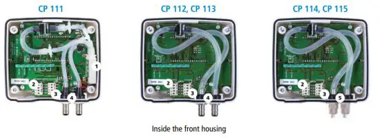
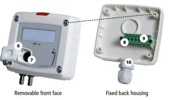
| 1. Solenoid valve (CP 111 only) 2. Left DIP switch 3. Right DIP switch 4. Pressure connections 5. Safety pressure connections | 6. Autozero 7. LCC-S software connection 8. Output terminal block 9. Power supply terminal block 10. Cable gland |
Electrical connections as per NFC15-100 standard
This connection must be made by a qualified and trained technician. To make the connection, the transmitter must NOT BE ENERGIZED.
| For CP 111/112/113/114/115 – AO models and CP 111/112/113/114/115 – AN models with 0-10 V or 4-20 mA output – active, 4 wires: | To make a 3-wire connection, BEFORE POWERING UP THE TRANSMITTER, please connect the output ground to the input ground. See drawing below. |
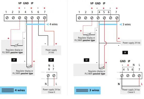 | |
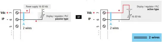
For CP 111/112/113/114/115 – PO models and CP 111/112/113/114/115 – PN models with 4-20 mA output – passive
Settings and use of the transmitter
Alimentation
16-30 Vdc + – Vdc IP + … 5 6 7 A autonome de + Auto-calibration CP 111 pressure transmitter has a temperature compensation of the gain from 0 to 50°C and an auto-calibration process that guarantees overtime excellent stability and perfect reliability of the measurement on low and high ranges. Auto-calibration principle: the microprocessor of the transmitter drives a solenoid valve that compensates for the possible drifts on the sensitive element over time. The compensation is
To configure the transmitter, it must not be energized. Then, you can make the settings required, with the DIP switches (as shown on the drawing below). When the transmitter is configured, you can power it up. performed by the permanent adjustment of the zero. So the measurement of the differential pressure is then independent of the environmental conditions of the transmitter. Advantage: no drift Frequency of auto-calibration: resettable or from 1 to 60 minutes.
Autozero
To perform an autozero, unplug the 2 pressure connections tubes and press the “Autozero” key.
On the CP 111 transmitter, it is not necessary to unplug the 2 pressure connection tubes. When an autozero has been performed, the “On” green light turns off then turns on, and on transmitters equipped with a display, “autos” is displayed.
Configuration
To configure the transmitter, unscrew the4 screws from the housing then open it. DIP switches allowing the different settings are then accessible.
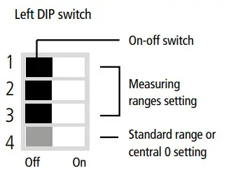
Measuring range settings – left DIP switch
To set a measuring range, but the 1, 2, and 3 on-off switches as indicated in the table below
CP 111, CP 112, CP 113
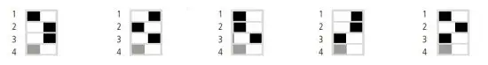 | |||||||||||||||
| Combination 1 | Combination 2 | Combination 3 | Combination 4 | Combination 5 | |||||||||||
| Type of transmitte | CP111 | CP112 | CP113 | CP111 | CP112 | CP113 | CP111 | CP112 | CP113 | CP112 | CP111 | CP113 | CP111 | CP112 | CP113 |
| Pa | 20 | 100 | 1000 | 30 | 250 | 2500 | 40 | 500 | 5000 | 50 | 750 | 7500 | 100 | 1000 | 10000 |
| mmH2 | 2 | 10 | 100 | 3 | 25 | 250 | 4 | 50 | 500 | 5 | 75 | 750 | 10 | 100 | 1000 |
| mbar | 0.2 | 1 | 10 | 0.3 | 2.5 | 50 | 0.4 | 5 | 50 | 0.5 | 7.5 | 75 | 1 | 10 | 100 |
| inWG | 0.08 | 0.4 | 4 | 0.12 | 1 | 10 | 0.16 | 2 | 20 | 0.2 | 3 | 30 | 0.4 | 4 | 40 |
| mmHg | 0.2 | 0.8 | 8 | 0.22 | 2 | 20 | 0.3 | 4 | 40 | 0.4 | 6 | 60 | 0.8 | 8 | 80 |
| daPa | 2 | 10 | 100 | 3 | 25 | 250 | 4 | 50 | 500 | 5 | 75 | 750 | 10 | 100 | 1000 |
| kPa | 0.02 | 0.1 | 1 | 0.03 | 0.25 | 2.5 | 0.04 | 0.5 | 5 | 0.05 | 0.75 | 7.5 | 0.1 | 1 | 10 |
| hPa | 0.2 | 1 | 10 | 0.3 | 2.5 | 25 | 0.4 | 5 | 50 | 0.5 | 7.5 | 75 | 1 | 10 | 100 |
- Measuring ranges of the CP 111 transmitter on the ±100 Pa range according to the measurement unit
- Measuring ranges of the CP 112 transmitter on the ±1000 Pa range according to the measurement unit
- Measuring ranges of the CP 113 transmitter on the ±10 000 Pa range according to the measurement unit
Example: - From 0 to 750 mmH2 O, the measuring range is 750 mmH2 O.
- From -500 Pa to +500 Pa, measuring range is 1000 Pa
CP 114, CP 115
| ||||||||||
| Combination 1 | Combination 2 | Combination 3 | Combination 4 | Combination 5 | ||||||
| Type of transmitter | CP114 | CP115 | CP114 | CP115 | CP114 | CP115 | CP114 | CP115 | CP114 | CP115 |
| mbar | 100 | 500 | 200 | 750 | 300 | 1 000 | 400 | 1 500 | 500 | 2 000 |
| inWG | 40 | 200 | 80 | 300 | 120 | 400 | 160 | 600 | 200 | 800 |
| kPa | 10 | 50 | 20 | 75 | 30 | 100 | 40 | 150 | 50 | 200 |
| PSI | 2 | 10 | 4 | 15 | 6 | 20 | 8 | 30 | 10 | 40 |
| mmHg | 80 | 400 | 160 | 600 | 240 | 800 | 320 | 1 200 | 400 | 1 600 |
| mmH2 | 1 000 | 5 000 | 2 000 | 7 500 | 3 000 | 10 000 | 4 000 | 15 000 | 5 000 | 20 000 |
| daPa | 1 | 5 | 2 | 7.5 | 3 | 10 | 4 | 15 | 5 | 20 |
| hPa | 100 | 500 | 200 | 750 | 300 | 1 000 | 400 | 1 500 | 500 | 2 000 |
- Measuring ranges of the CP 114 transmitter on the ±500 mbar range according to the measurement unit.
- Measuring ranges of the CP 115 transmitter on the ±2000 mbar range according to the measurement unit.
Example: - From 0 to 750 mmH2 O, the measuring range is 750 mmH2 O.
- From -500 mbar to +500 bar, the measuring range is 1000 bar.
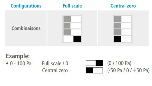
Standard range / central zero setting – left DIP switch
Please follow carefully the combinations besides the DIP switch. If the combination is wrongly done, the following message will appear on the display of the transmitter “CONF ERROR”. In that case, you will have to unplug the transmitter, place the DIP switches correctly, and then power the transmitter up.
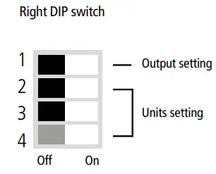
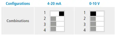
Output setting – right DIP switch
(CP 111/112/113/114/115 – AO and CP 111/112/113 – AN models) To set the type of analog output, please put the on-off switch of the output as shown beside.
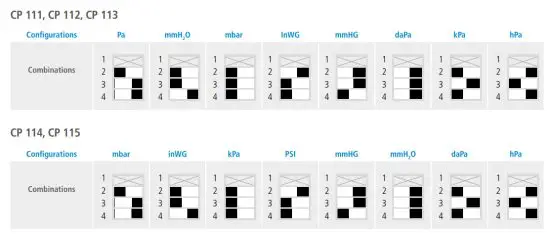
Units setting – right DIP switch
To set a measurement unit, but the on-off switches 2, 3, and 4 of the units as shown in the table below.
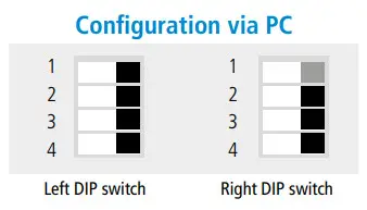
Configuration via LCC-S software (option)
An easy and friendly configuration with the software! You can configure your own intermediary ranges.
The minimum difference between the high range and the low range is 20.
For example, it is possible to set the instrument from -20 to 0 Pa, from 0 to +20 Pa, or from -10 to +10 Pa… To access the configuration via software: set the DIP switches as
shown beside.
Note: the on-off switch 1 of the right DIP switch can be in any position (selection of the analog output 0-10 V or 4-20 mA). Connect the cable of the LCC-S to the connection of the transmitter.
The configuration of the parameters can be done either with the DIP switch or via software (you cannot combine both solutions).
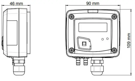
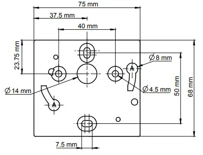
Mounting
To mount the transmitter, mount the ABS plate on the wall (drilling: Ø 6 mm, screws and pins are supplied). Insert the transmitter on the fixing plate (see A on the drawing beside). Rotate the housing in a clockwise direction until you hear a “click” which confirms that the transmitter is correctly installed.
Once the transmitter is installed and powered up, please make an autozero to guarantee the correct working of the transmitter in any position.
Accessories
Please refer to the datasheet to get more information about available accessories.
| Maintenance: please avoid any aggressive solvent. Please protect the transmitter and its probes from any cleaning product containing formalin, that may be used for cleaning rooms or ducts. | Precautions for use: please always use the device in accordance with its intended use and within parameters described in the technical features in order not to compromise the protection ensured by the device. |
Download the LCC-S software user manual
https://sauermanngroup.com/en-INT/measuring-instruments/transmitters/software/lcc-s

https://sauermanngroup.com/en-INT/measuring-instruments/transmitters/pressure-transmitters
![]() Customer service portal
Customer service portal
Utilisez notre Portail service clients pour nous contacter
Use our Customer service portal to contact us
https://sauermann-en.custhelp.com
www.sauermanngroup.com