![]() CPE 310 Flush Mount Multifunction Pressure Transmitter
CPE 310 Flush Mount Multifunction Pressure Transmitter
User Guide CPE 310
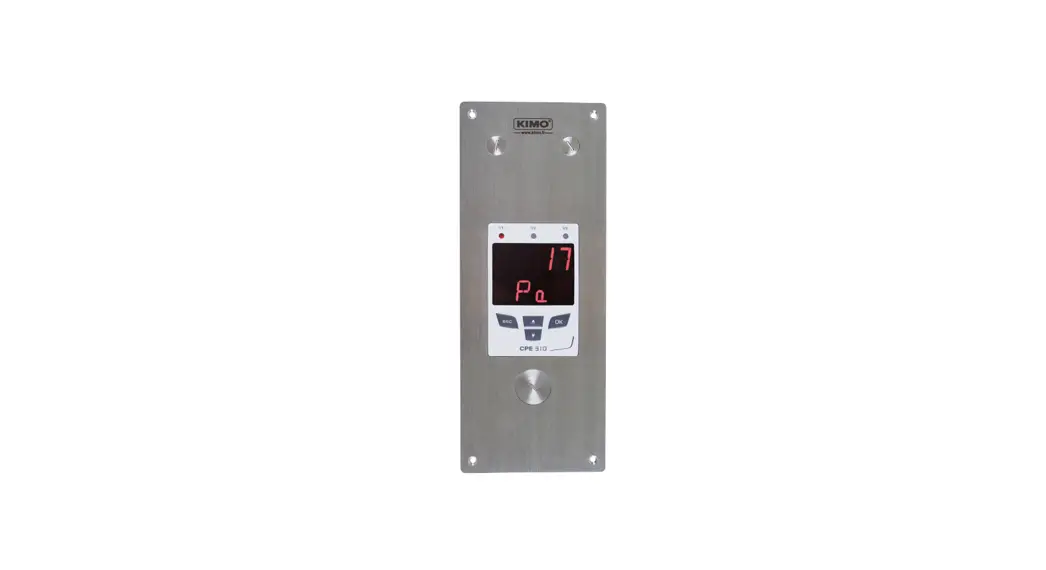
Flush-mount multifunction pressure transmitter
| Input for interchangeable probe (Class 310) | |
| 3 analogue outputs 0-5/10 V or 0/4-20 mA | |
| 3 audible and visual alarms | |
| MODBUS network RS485 system (optional) |
General features
| Power supply | 24 Vac / Vdc ±10% |
| Output | 3 x 0/4-20 mA or 3 x 0-5/10 V (4 wires) Common mode voltage Maximum load: 500 Ohms (0/4-20 mA) / Minimum load: 1 K Ohms (0-5/10 V) |
| Galvanic isolation | On the output |
| Consumption | 5 VA |
| Conformity | 2014/30/EU EMC; 2014/35/EU Low Voltage; RoHS 2011/65/EU (EU)2015/863; 2012/19/EU WEEE |
| Electrical connection | Screw terminal block for cables from 0.05 to 1.5 mm2 or from 30 to 16 AWG Carried out according to the code of good practice |
| RS485 communication | Digital: ModBus RTU protocol, configurable communication speed from 2400 to 115200 Bauds (optional) |
| Visual alarm | Blinking of the value |
| Audible alarm | Buzzer (70 dB at 10 cm) |
| Environment and type of fluid | Air and neutral gases |
| Conditions of use (°C/%RH/m) | From -10 to +50 °C. In non-condensing condition. From 0 to 2000 m |
| Storage temperature | From -10 to +70 °C |
Features of the housing
Symbols used![]() For your safety and in order to avoid any damage of the device, please follow the procedure described in this document and read carefully the notes preceded by the following symbol:
For your safety and in order to avoid any damage of the device, please follow the procedure described in this document and read carefully the notes preceded by the following symbol:![]() The following symbol will also be used in this document, please read carefully the information notes indicated after this symbol:
The following symbol will also be used in this document, please read carefully the information notes indicated after this symbol:
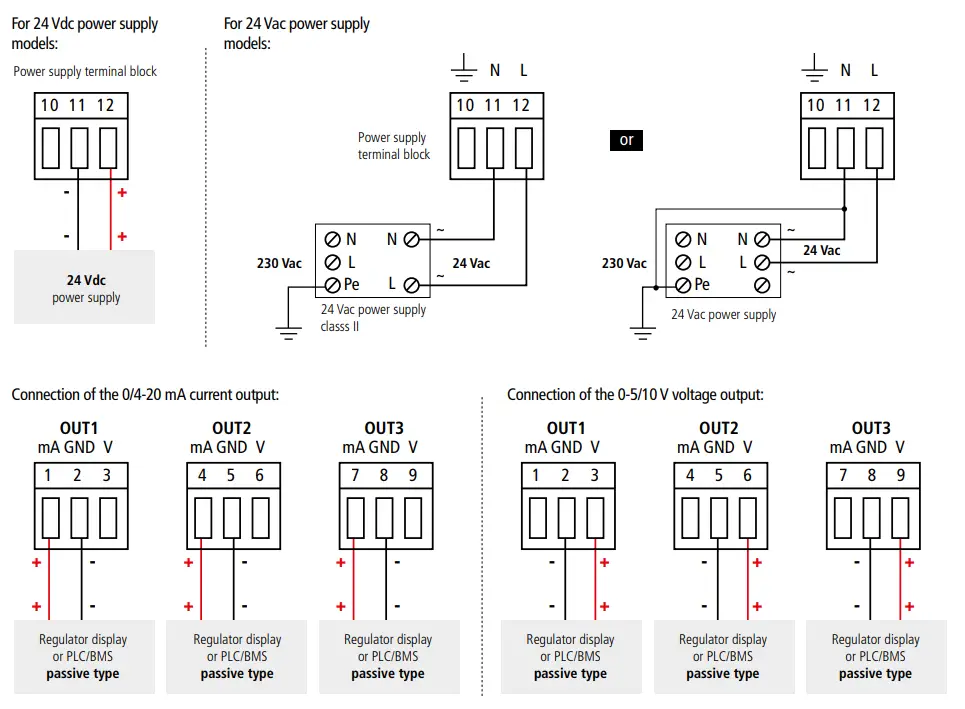
Connections
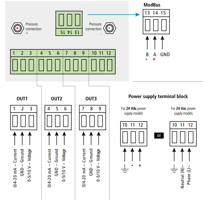
Electrical connections as per NFC15-100 standard
This connection must be made by a formed and qualified technician. Whilst making the connection, the transmitter must not be energized. The presence of a switch or a circuit breaker upstream the device is compulsory.
Configuration
Class 310 transmitters allows you to set all the parameters managed by the transmitter: units, measuring ranges, alarms, outputs, channels… via the different methods shown below:
- Via the keypad, only on models with display. A code-locking system for keypad guarantees the security of the installation. See configuration manual.
- Via software (optional): simple and user-friendly. See LCC-S user manual.
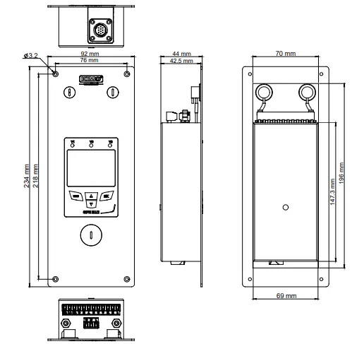
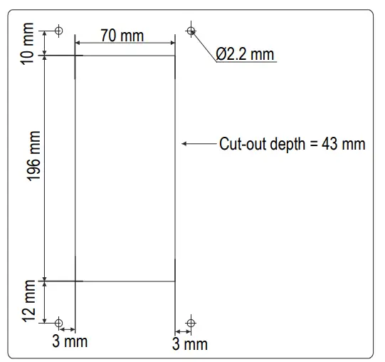
Mounting
To install a transmitter on a wall, make a cutting of 198 x 72 mm in the wall.
Then drill 4 holes around the cutting as shown beside.
Insert the transmitter into the wall and fix it with the 4 screws (supplied with the transmitter).
Accessories
Please refer to the data sheet to get more information about available accessories.
Maintenance: please avoid any aggressive solvents. Please protect the transmitter and its probes from any cleaning product containing formalin, that may be used for cleaning rooms or ducts.
Precautions for use: please always use the device in accordance with its intended use and within parameters described in the technical features in ordernot to compromise the protection ensured by the device.
Download the full manual