
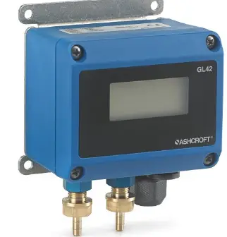
ASHCROFT GL42 Differential Pressure Transmitter
WARNING READ BEFORE INSTALLATION
- GENERAL
A failure resulting in injury or damage may be caused by excessive overpressure, excessive vibration or pressure pulsation, excessive instrument temperature, corrosion of the pressure-containing parts, or another misuse. Consult Ashcroft Inc., before installing if there are any questions or concerns. - OVERPRESSURE
Pressure spikes in excess of the rated overpressure capability of the transducer may cause irreversible electrical and/or mechanical damage to the pressure measuring and containing elements. - STATIC ELECTRICAL CHARGE
Any electrical device may be susceptible to damage when exposed to static electrical charges. To avoid damage to the transducer the operator/installer should follow proper ESD (electrostatic discharge) protection procedures before handling the pressure transducer. - DESCRIPTION
The Ashcroft® Model GL42 is a low differential pressure transmitter to be used on clean, dry, non-corrosive gases. It is available in two accuracy classes and its performance is traceable to the U. S. National Institute of Standards and Technology (NIST). The 7 or 5 located in the fifth position of the product code distinguishes a 1.0% from a 0.5% accuracy transmitter. Both unidirectional (e.g. 0 to +1.0 IW) or bi-directional (e.g. ±2.0 IW) models are available.
SPECIFICATIONS
- Reference condition: 77°F (25°C) Accuracy*: ±0.50% or ±1.00% F.S. (URL) (* includes linearity, hysteresis and repeatability)
- Repeatability: ≤ ±0.1 % F.S.
- Stability: </= 0.5% F.S. / Year Zero / Span Adjustment: ±5% F.S.
- Standard-Ranges (Unidirectional): 0.10˝ to 25.00˝ in H20
- Standard-Ranges (Bidirectional): ±0.05˝ to ±15.0˝ in H20
- ENVIRONMENTAL SPECIFICATIONS
- Enclosure Rating: IP65
- Temperature Limits:
- Operating: –4/158°F (–20/70°C)
- Storage: -40/194°F (–40/90°C)
- Compensated: 35/129°F (2/54°C) (10-90% R.H. non-condensing)
- Temperature Coefficients: Zero & Span ±0.06%/K within 35/129°F (2/54°C) Ref. 77°F (25°C)
- FUNCTIONAL SPECIFICATIONS
Static (line) Pressure: All Pressure Ranges- Proof: 14.5 psi (1 bar)
- Burst: 24.65 psi (1.7 bar) Max.
- Static: 24.65 psi (1.7 bar)
- ELECTRICAL SPECIFICATIONS LCD
- Display: 4 Digit
- LCD Screen Dimensions: Width: 1.77” (45mm) / Height: 0.75” (19mm)
- LCD Character Size: Height: 0.21” (5.4mm) / Width: 0.45” (11.5mm)
- Output Signal: 4-20 mA ( 2 wire)
- Supply Voltage: 19-36 Vdc (Nominal 24 Vdc)
- Rangeability / Adjustment: Zero: ±1/3 F.S.
- CE-Compliance: EN 61000-4-2, EN 61000-4-3
- MECHANICAL SPECIFICATIONS
- Process Connection: Brass / Aluminum
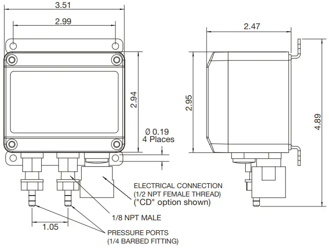
1/8” Female NPT or 1/4” Male Barbed Fitting - Electrical Connection:
½” Female DIN Cable Conduit (Standard)
PG9 Cable Gland (Option - Enclosure: Nylon
- Cable Connection Socket: Nylon
- Front Foil: Polyester
- Electrical Connection: Screw Terminal
- Weight: 9.9 oz (308 g)
- Mounting:
Wall Mount (Standard) DIN Rail (Option): EN 50022 / EN 50035 / EN 50045
Panel Mount (Option)
- Process Connection: Brass / Aluminum
- INTENDED USE
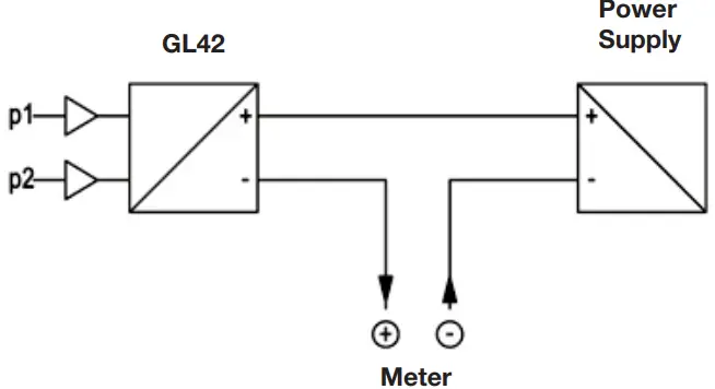
The GL42 is a 2-wire transmitter.
It is suitable for accurate measurement of low gauge, vacu-um or differential pressure of non-conductive and non-corro-sive gaseous media. - PRODUCT DESCRIPTION AND FUNCTION
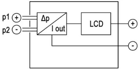
- Function diagram

- Design and mode of operation
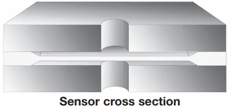
The transmitter is based on a capacitance sensor element with a micro machined differential capacitor using a patented silicon-on-glass technology. This ultra-thin single crystal dia-phragm provides excellent sensor repeatability and stability.
The silicon diaphragm sensor has no glues or other organics to contribute a drift or mechanical degradation over time.
- Function diagram
INSTALLATION AND ASSEMBLY
All supply lines should be arranged so that there are no me-chanical forces acting on the device.
The GL42 is calibrated for vertical installation; however any installation position is possible. If an installation position other than vertical is selected, the zero-point signal can be corrected as shown in Section 13b.
- Process connection
- By authorized and qualified personnel only.
- All lines need to be depressurized when the instrument is being connected.
- Appropriate steps must be taken to protect the device from pressure surges.
- Check the suitability of the device for the media to be measured.
- Maximum pressures shall be observed.
- Check that all connections are tight before use.The pressure sensing lines need to be kept as short as pos-sible and installed without sharp bends to avoid interfering delay times.
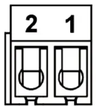
The pressure connections are marked with (+) and (-) sym-bols on the device. For differential pressure measurements, the higher pressure is connected to the (+) side and the lower pressure to the (-) side of the device.
If during installation the pressure measuring lines are already under pressure, the zero-point cannot be checked and no settings can be adjusted. In these cases, the device should only be connected electrically first.
- Electrical connection
- By authorized and qualified personnel only.
- The electrical connection of the device shall be per-formed according to local electrical codes
- Turn off power before connecting the device.

- 2-wire circuit

Pin Signal Name 2 + Power Supply / Output Signal +Ub / +Sig 1 – Power Supply / Output Signal -Ub / -Sig - Pin assignment
- Process connection
- COMMISSIONING
All electrical supply, operating and measuring lines, and the pressure connections must have been correctly installed be-fore commissioning. All supply lines are arranged so that there are no mechanical forces acting on the device.
Check that the pressure connections do not leak before commissioning.- Configuration of the LCD display
To configure the LCD display, remove the lid by unscrewing
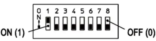
the four screws on the front of the device. This gives you ac-cess to the DIP switch used for configuration.S1 S2 S3 S4 S5 S6 S7 S8 Unit Decimal Point Attenuation reserved The following overview shows the basic function of the indi-vidual switches:
Using the following switch settings, the display can now be configured at your discretion. Changes to the configuration via the DIP switch are shown immediately on the display.
A “1” equals the switch setting “ON”; a “0” means that the switch setting is “OFF”.Unit S1 S2 S3 S4 S5 S6 S7 S8 inWC 0 0 X X mbar 1 0 X X kPa 0 1 X X Pa 1 1 X X Decimal Point S1
S2
S3
S4
S5
S6
S7
S8
0 0 0 X X 1.0 1 0 X X 2.00 0 1 X X 3.000 1 1 X X Display Damping
S1
S2
S3
S4
S5
S6
S7
S8
none 0 0 X X 1 s 1 0 X X 3 s 0 1 X X 5 s 1 1 X X - Switch settings
- Functional description of display damping
The damping only refers to the display value of the LCD dis-play and not the power output signal of the GL42 2-wire dif-ferential pressure transmitter.
The display value is damped according to an e-function. The set damping time corresponds to a change of the displayed pressure value of 90% of the change of the input pressure.
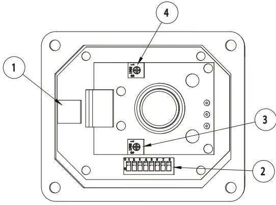
Item Description 1 KL1 – PCB Terminal Block for power supply and signal output 2 S1 – DIP Switch for LCD Configuration 3 SPAN Adjustment Potentiometer 4 ZERO Adjustment Potentiometer The final display value is achieved after a four-fold damping time.
- Adjustment
To adjust the differential pressure transmitter, remove the lid by unscrewing the four screws on the front of the device.
The zero-point and the range can be adjusted via the poten-tiometer “ZERO” (zero-point) and “SPAN” (range). Ensure correct alignment of the sensor in terms of the subsequent installation to avoid position-dependent measuring deviations when used later.
- Configuration of the LCD display
MAINTENANCE
The device does not require maintenance. In order to ensure reliable operation and a long service life of the device we recommend regular checking of the device as follows:
- Check the function in connection with system components.
- Check the tightness of the pressure connection lines.
- Check the electrical connections.The exact test cycles have to be adapted to the operating and environmental conditions. The operating manuals of all other devices are also to be observed if there is an interac-tion of different device components.
- TRANSPORT
The product must be protected against severe impacts. Therefore transport is to be effected only in the packaging in-tended for transport. - SERVICE
All defective or faulty devices are to be sent directly to Ash-croft Inc. We would ask you to coordinate all device returns with our inside sales department. Our inside sales depart-ment will issue an RMA number and give instructions on how to ship the return.
WARNING
Remaining medium in and on dismantled measuring instru-ments may cause danger to persons, environment and equip-ment. Take reasonable precautions! Clean the instru-ment thoroughly if necessary.
To return the unit please choose the original packaging or a packaging intended for transport. - DISPOSAL
Incorrect disposal can put the environment at risk.
Kindly help us protecting the environment and dispose of or recycle the used products in accordance with the relevant regulations. - DIMENSIONED DRAWINGS
(All units in mm unless otherwise specified.
© 2015 Ashcroft Inc. 250 East Main Street, Stratford, CT 06614 USA. Tel: 203-378-8281, Fax: 203-385-0402 www.ashcroft.com All sales subject to standard terms and conditions of sale. I&M011-10227 06/15


