ASHCROFT E2 Pressure Transducer Instruction Manual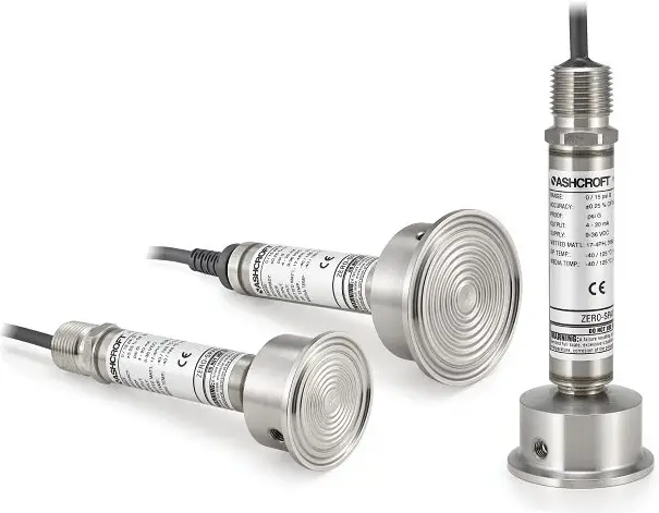
![]() WARNING! READ
WARNING! READ
BEFORE INSTALLATION
A failure resulting in injury or damage may be caused by excessive overpressure, excessive vibration or pressure pulsation, excessive instrument temperature, corrosion of the pressure containing parts, or other misuse. Consult Ashcroft Inc., Stratford, Connecticut, USA before installing if there are any questions or concerns
OVERPRESSURE
Pressure spikes in excess of the rated overpressure capability of the transducer may cause irreversible electrical and/or mechanical damage to the pressure measuring and containing elements.
Fluid hammer and surges can destroy any pressure transducer and must always be avoided. A pressure snubber should be installed to eliminate the damaging hammer effects. Fluid hammer occurs when a liquid flow is suddenly stopped, as with quick closing solenoid valves. Surges occur when flow is suddenly begun, as when a pump is turned on at full power or a valve is quickly opened.
Liquid surges are particularly damaging to pressure transducers if the pipe is originally empty. To avoid damaging surges, fluid lines should remain full (if possible), pumps should be brought up to power slowly, and valves opened slowly. To avoid damage from both fluid hammer and surges, a surge chamber should be installed.
Symptoms of fluid hammer and surge’s damaging effects:
- Pressure transducer exhibits an output at zero pressure (large zero offset).
- Pressure transducer output remains constant regardless of pressure
- In severe cases, there will be no output.
FREEZING
Prohibit freezing of media in pressure port. Unit should be drained (mount in vertical position with electrical termination upward) to prevent possible over- pressure damage from frozen media.
STATIC ELECTRICAL CHARGES
Any electrical device may be susceptible to damage when exposed to static electrical charges. To avoid damage to the transducer, observe the following:
- Operator/installer should follow the proper ESD (electrostatic discharge) protection procedures before handling the pressure transducer.
- Ground the body of the transducer BEFORE making any electrical connections
- When disconnecting, remove the ground LAST!
Note: The shield and drain wire in the cable (if supplied) is not connected to the transducer body, and is not a suitable ground.
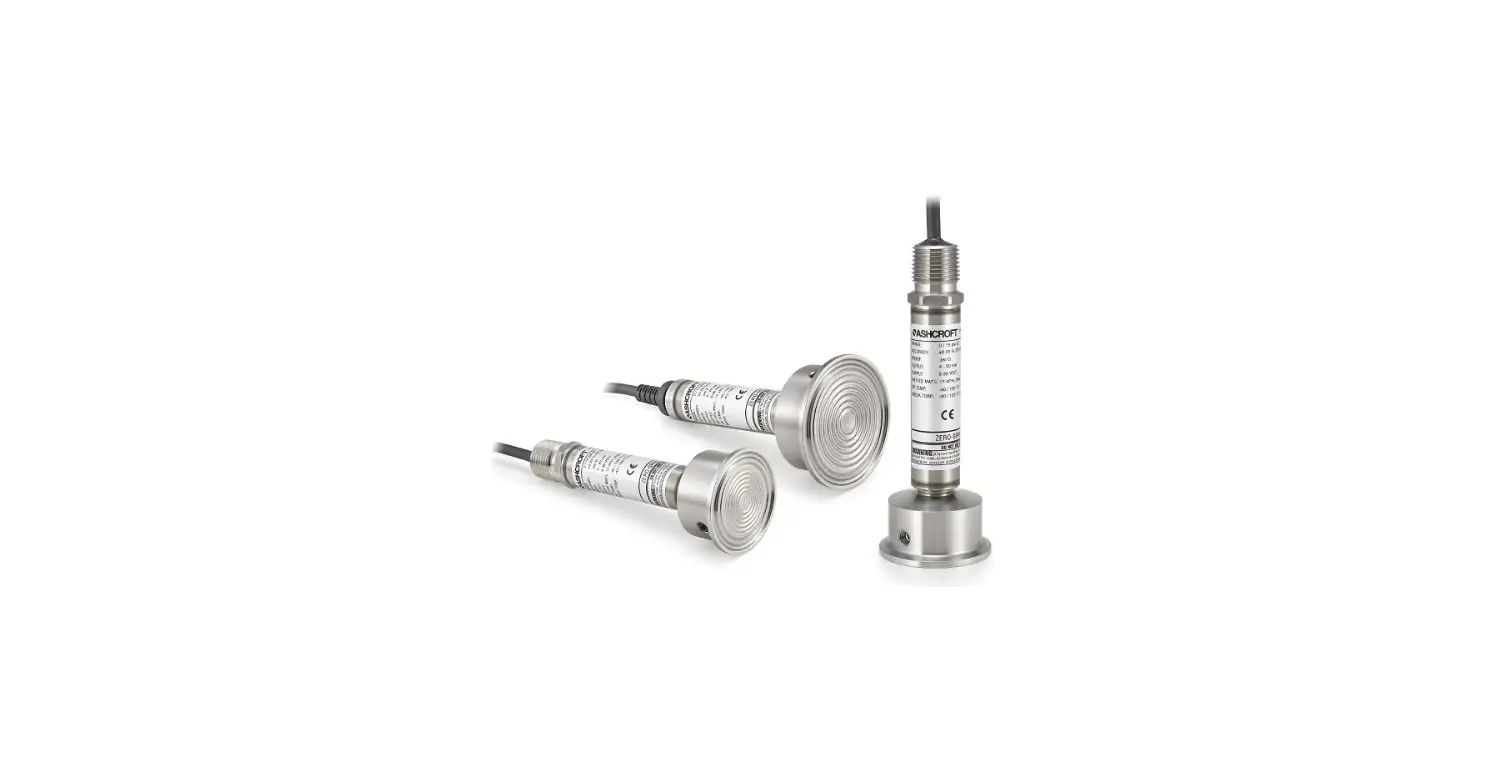
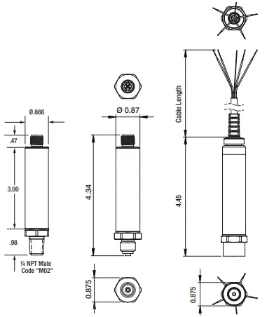
ASHCROFT® E2 PRESSURE TRANSMITTER, TYPICAL DIMENSIONS AND CONSTRUCTION
ASHCROFT® E2 PRESSURE TRANSMITTER, AVAILABLE OPTIONAL HAZARDOUS LOCATION APPROVALS
![]()
DESCRIPTION
The Ashcroft® Model E2 is ideal for a broad range of pressure sensing requirements found in general and heavy industrial applications as well as applications in test and measurement. The E2 offers a wide variety of material, process and electrical connections to meet your application requirements. It is designed for use with both liquids and gases it provides an accurate, reliable and highly repeatable output. This is accomplished through the use of an onboard microprocessor that is programmed during a unique digital compensation process to provide an extremely linear performance over the entire specified pressure and temperature range.
SPECIFICATIONS
Reference condition: 70°F (21°C)
Accuracy: ±0.25%, ±0.50% or ±1.00% of Span Terminal Point (* includes linearity, hysteresis, repeatability zero offset and span)
Repeatability: ≤ ±0.1 % of Span
Stability: ±0.25% of Span / Year
Zero / Span Adjustment: ±5% of Span
Standard Ranges: VAC to 20,000 psi
ENVIRONMENTAL SPECIFICATIONS
Enclosure Rating: IP66 standard, IP67 and IP69K Consult Factory
Temperature Limits:
Storage Temp: -50 to 125°C
Operating Ambient Temp: -40 to 125°C
Media Temp: -40 to 125°C * (0-100% R.H. non-condensing)
Temperature Coefficients: Zero & Span ±0.009%/°C within -40 to 125°C
Vibration: Random: 10g RMS 20-2000 Hz
Shock: 80g Peak, 6 msec, 3 axes, haversine
Proof pressure: 1.2X -2X the range
Burst pressure: 3X-8X the range minimum
FUNCTIONAL SPECIFICATIONS
ELECTRICAL SPECIFICATIONS
Analog Output: 4-20 mA, 20-4 mA (2-wire), 1-5Vdc, 1-6Vdc, 0-5Vdc, 0-10Vdc, 1-11Vdc, 0.1-5Vdc, 0.1-10Vdc, 0.5V-4.5Vdc
Supply Voltage:
9-36Vdc: (4-20mA, 1-5Vdc, 1-6Vdc,
0.1-5Vdc, 0.1-10Vdc)
14-36Vdc: (0-10Vdc, 0-11Vdc, 0.1-10Vdc)
Supply Current: <8 mA (Vout)
Response Time (Output): 4msec <8 mA
Power-Up Response Time: 100msec
Current Source/Sink for Voltage Output: 1
mA (Source) / 0.1mA (Sink) maximum
Withstand/Breakdown: 100 Vdc / 100 Vac. Optional 500Vdc / 500Vac
EMC: CE Industrial EN 61326-1, EN 61326-2-3, EN 61326-3
ESD: 4KV Contact/8kV Air IEC 61000-4-2
RFI: 10V/m 80-1000MHz IEC 61000-4-3
EFT: IEC 61000-4-4
Surge: IEC 61000-4-5 (shielded cable)
Common Mode: IEC61000-4-6
Radiated Power Frequency: IEC61000-4-8
Conducted Emissions: EN55011/FCC
CE: EMC
Insulation Resistance: >100M @ 30V
RoHS2: Yes
MECHANICAL SPECIFICATIONS
Process Connections: Male NPT (1 ⁄8, ¼ and ½), Female NPT (1 ⁄8, ¼ and ½), 7 ⁄16-20 UNF SAE (Male and Female), MIL 33656 (UNJF 7⁄16-20 w/ 37° Cone), G¼˝ B EN837-1, G½˝ B EN837-1,G¼˝ A DIN3852-E, Autoclave HP 7⁄16˝(AMINCO), 1⁄8˝ BSP Tapered Thread, ¼˝ BSP
Tapered Thread, ½˝ BSP Tapered Thread, ¼˝ Male VCR, ¼˝ Female VCR, R1 ⁄8 ISO 7/1, Sanitary seal 1.5˝ Tri-clamp and 2.0˝ Tri-clamp
Electrical Connections: Cable (vented and non-vented), ½˝ Conduit with shielded cable: 24AWG+drain vented or non-vented, ½˝ Conduit with Flying Leads: 18AWG 3 conductor, non-vented, M20 Conduit with Cable/ Flying Leads, Mini Hirschmann G, Bendix 4-pin MIL-DTL-26482(3112), M12 (4-pin), Form A EN175301-803 (DIN A43650), Form C EN 175301-803 (DIN C 43650), Deutsch DT04-3P or DTM04-3P, AMP Superseal, Metri-Pack 3-Pin Packard.
Diaphragm Materials: 17-4PH SS, 316SS or A28
INSTALLATION AND ASSEMBLY
![]()
©2020 Ashcroft Inc., 250 East Main Street, Stratford, CT 06614-5145, USA,
Tel: 203-378-8281, Fax: 203-385-0499,
www.ashcroft.com
All sales subject to standard terms and conditions of sale. e2g_transducer_i&m_I&M011-10265_RevC_07-31-20


