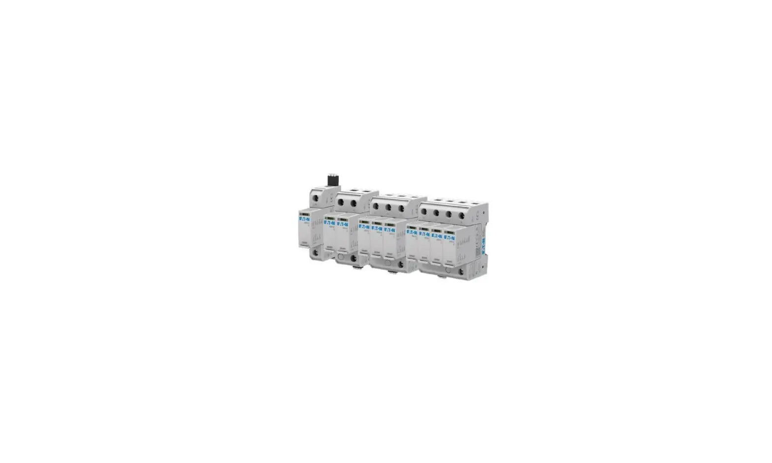
EATON AG II IT DN120xxR AC Surge Protection Device

Eaton Corporation, 1000 Eaton Boulevard, Cleveland, OH 44122, United States
© 2022 by Eaton, www.eaton.com
INSTRUCTION
Please read the following before installing your Surge Protective Device:
- Verify the system voltage and configuration on the label is appropriate for the application.
- Risk of Electric Shock – Installation and maintenance should be performed by qualified personnel only.
- Disconnect from energized circuits before installing or servicing.
- Safety rules and regulations applicable to all devices connected to power lines should always be followed. National standards and safety regulations must be followed.
- The external mechanical integrity of the device must be checked before installation. Products with visible damage should not be installed.
- Its use is only permitted within the limits shown and stated in these installation instructions. Opening or tampering with the device invalidates the warranty.
- Connecting leads shall be kept as short as possible, without loops and not exceed 0.5m in total length per SPD.
- The minimum distance of the SPD from any grounded conductive surface at which the SPD can be installed is 0 mm.
- This is open type SPD intended for installation within a suitable enclosure in accordance with the National Electrical Code, ANSI/NFPA 70.
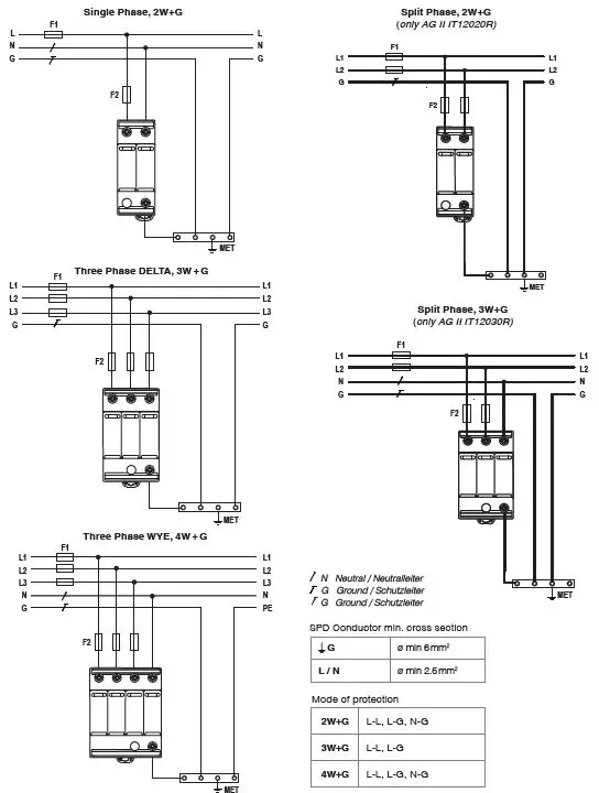
PROTECTION CONFIGURATIONS
DIMENSIONS
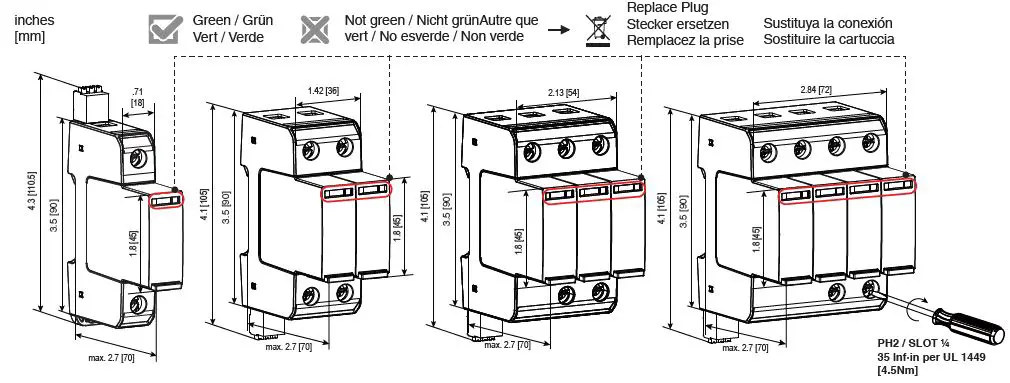
For UL Listed products left G Conductor Terminal is covered/closed
TECHNICAL DATA
| TECHNICAL DATA | Product name | AG II IT DN120xxR | AG II IT DN240xxR | AG II IT DN277xxR | AG II IT DN400xxR | AG II IT DN600xxR | |
| Uo /Un | AC (50-60Hz) | 120 V + 10% | 240 V + 6% | 277 V + 10% | 400V + 10% | 600 V + 10% | |
| UC/MCOV | AC | 150V | 300V | 350V | 480V | 750V | |
| Up | 1250 V | 1500 V | 1750 V | 2300 V | 3400 V | ||
| VPR | 600 V | 900 V | 1000 V | 1500 V | 2500 V | ||
| In (8/20) | 20 kA | 20 kA | 20 kA | 20 kA | 20 kA | ||
| In (8/20) (per UL 1449) | 20 kA | 20 kA | 20 kA | 20 kA | 20 kA | ||
| Imax (8/20) | 50 kA | 50 kA | 50 kA | 50 kA | 35 kA | ||
| ISCCR / Backup fuse (per IEC 61643-11) | 50 kA / 250A gG fuse 25 kA / 315A gG fuse | 50 kA / 250A gG fuse 25 kA / 315A gG fuse | 50 kA / 250A gG fuse 25 kA / 315A gG fuse | 50 kA / 250A gG fuse 25 kA / 315A gG fuse | 50 kA / 250A gG fuse 25 kA / 315A gG fuse | ||
| SCCR (per UL 1449) | 200 kA | 150 kA | 200 kA | 200 kA | 200 kA | ||
| IPE | ≤ 0.400 mA | ≤ 0.400 mA | ≤ 0.400 mA | ≤ 0.400 mA | ≤ 0.400 mA | ||
| Ta | -40 ºF to +158 ºF / 185 ºF per UL 1449 [-40 ºC to +70 ºC / 85 ºC per UL 1449] | ||||||
| RH | 5 %…95 % | ||||||
| Mounting | 35mm DIN rail, EN 60715 | ||||||
| Altitude (max) | 13123 ft [4000 m] | ||||||
| Location / Number of ports / IP | Indoor / 1 / 20 (built-in) | ||||||
| Warranty | 1 year | ||||||
| Terminals: | |||||||
| ø min 14 AWG / ø max 6 AWG per UL 1449 [ø min 1.5 mm2 / ø max 35 mm2] | |||||||
| ø min 14 AWG / ø max 6 AWG per UL 1449 [ø min 1.5 mm2 / ø max 35 mm2] | |||||||
| ø min 30 AWG / ø max 10 AWG per UL 1449 [ø min 0.25 mm2 / ø max 1.5 mm2 ] | |||||||
REMOTE CONTACT STATES
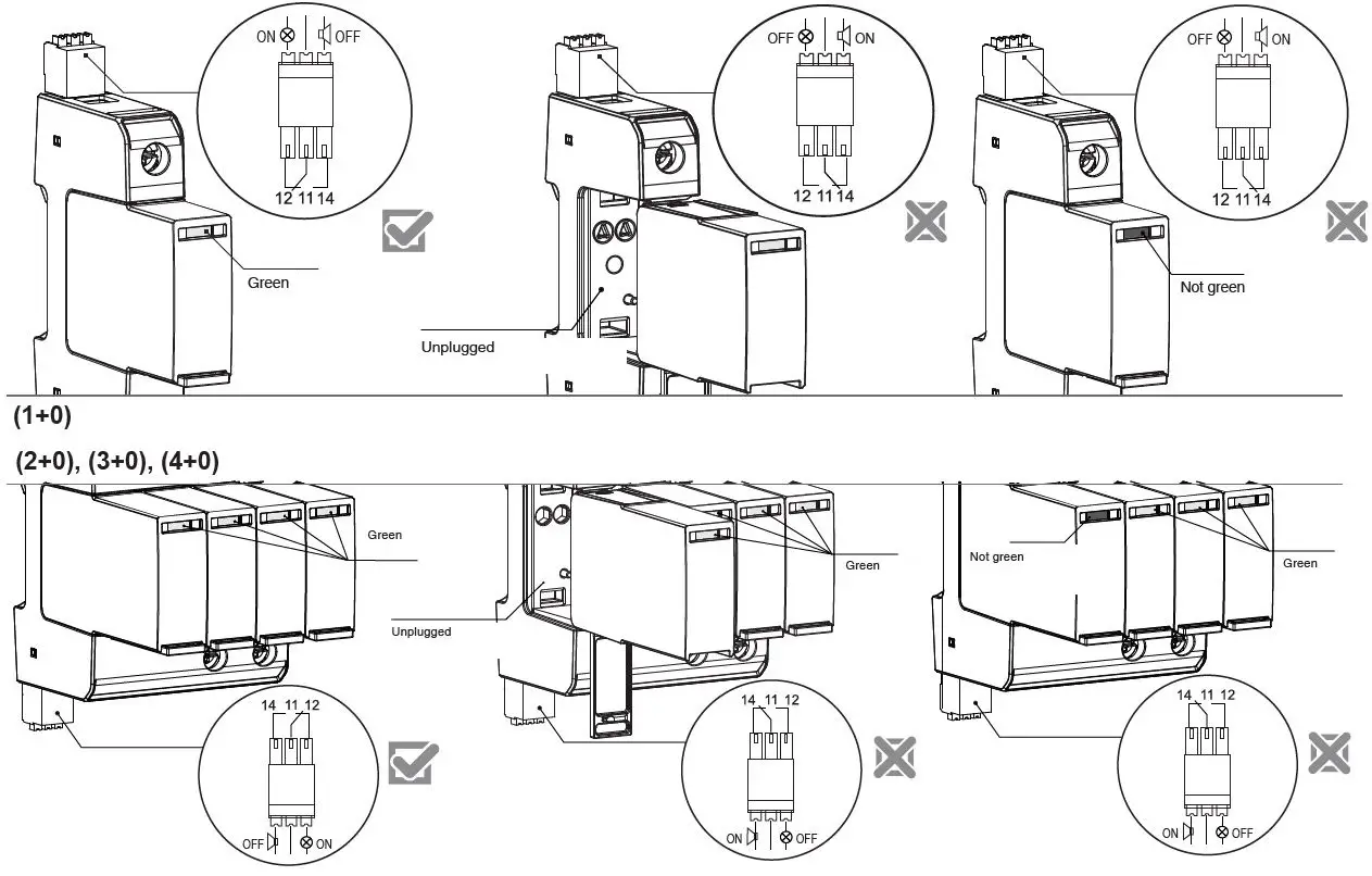
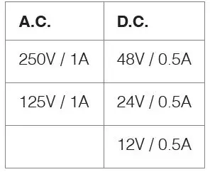
| RC contact(s) states | 11- 12 | 11-14 |
| SPD module(s) functional / installation is protected | Closed Geschlossen | Open Offen |
| SPD module(s) unplugged or non-functional | Open Offen | Closed Geschlossen |
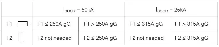
BACKUP FUSE
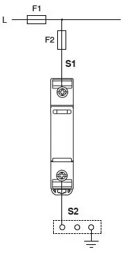
Protection against short circuit
NOTE: If the ISCCR is declared higher than 50kA up 100 kA use 160A gG fuse.
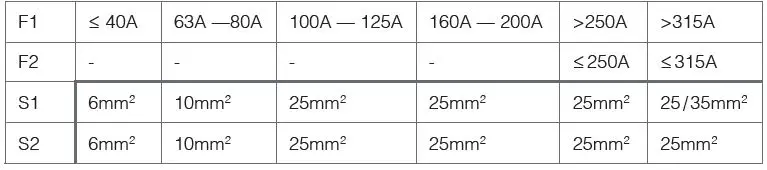
Conductor Dimensioning
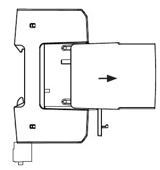
PLUG REPLACEMENT
Step 1: Unlock
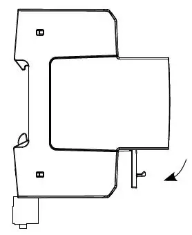
Step 2: Pull module out
03.2022a / All Rights Reserved
For more information, please contact the Eaton Technical Resource Center at 1-800-809-2772, option 4, option 2. You may submit inquiries via email to [email protected] and you can find more information at eaton.com/aegis.


