SIGNATURE SOLAR 1511004 12V 400AH EG4-LiFePower4 Lithium Battery Instruction Manual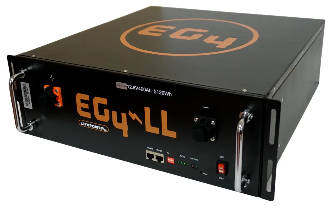
OVERVIEW
The EG4 series of Lithium iron phosphate battery modules are designed for maximum energy density. Perfect for use in Solar Systems, Off Grid Living, UPS/Energy Storage Scenarios, Portable Devices, RVs, Tiny Homes, Boats, and Lead Acid Conversion Applications. The battery modules include an integrated, intelligent Battery Management System (BMS) that monitors, manages, and logs all individual battery cell parameters. The BMS provides advantages on safety, cycle life, energy density, temperature range, over health and environmental protections
BEFORE YOU START:
Read all the safety information provided in this document prior to installing or operating the equipment. Contact Customer Support immediately for any questions or concerns,(903) 441-2090. To handle or operate the battery modules:
- Installation must be performed by a knowledgeable and qualified professional
- Read the complete user manual before operating or handling battery modules
- Remove any possible shorting risks from your body, such as metallic jewelry, watches, rings, necklaces, etc
- All tools shall be insulated
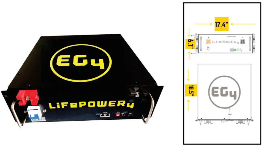
MODEL PARAMETERS / SPECIFICATIONS
| MODEL | VOLTAGE | CAPACITY | ENERGY | LENGTH | WIDTH | HEIGHT | WEIGH T (LBS) |
| 12V 400AH | 12.8V | 400AH | 5120WH | 442MM | 470MM | 155MM | 109 |
EG4 LIFEPOWER ADVANTAGES
This battery consists of prismatic LFP Cells, Wire, BMS, and Container
- 19” 3.5U Rack Mount Design
- Expandable up to 16 units
- Highest Performance LFP Cells with long life, safety features, and a wide temperature range
- Small Size, Light Weight, High Energy Density
- Single Cell Container is fire retardant, stable and safe
- Built-In 200AH BMS with voltage, current, temperature, and health management
- Integrated Bluetooth with APP for monitoring
- 10-20 Year Design Life
- Maintenance Free, 5 Year Warranty
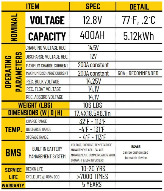
BATTERY MODULE SPECIFICATIONS
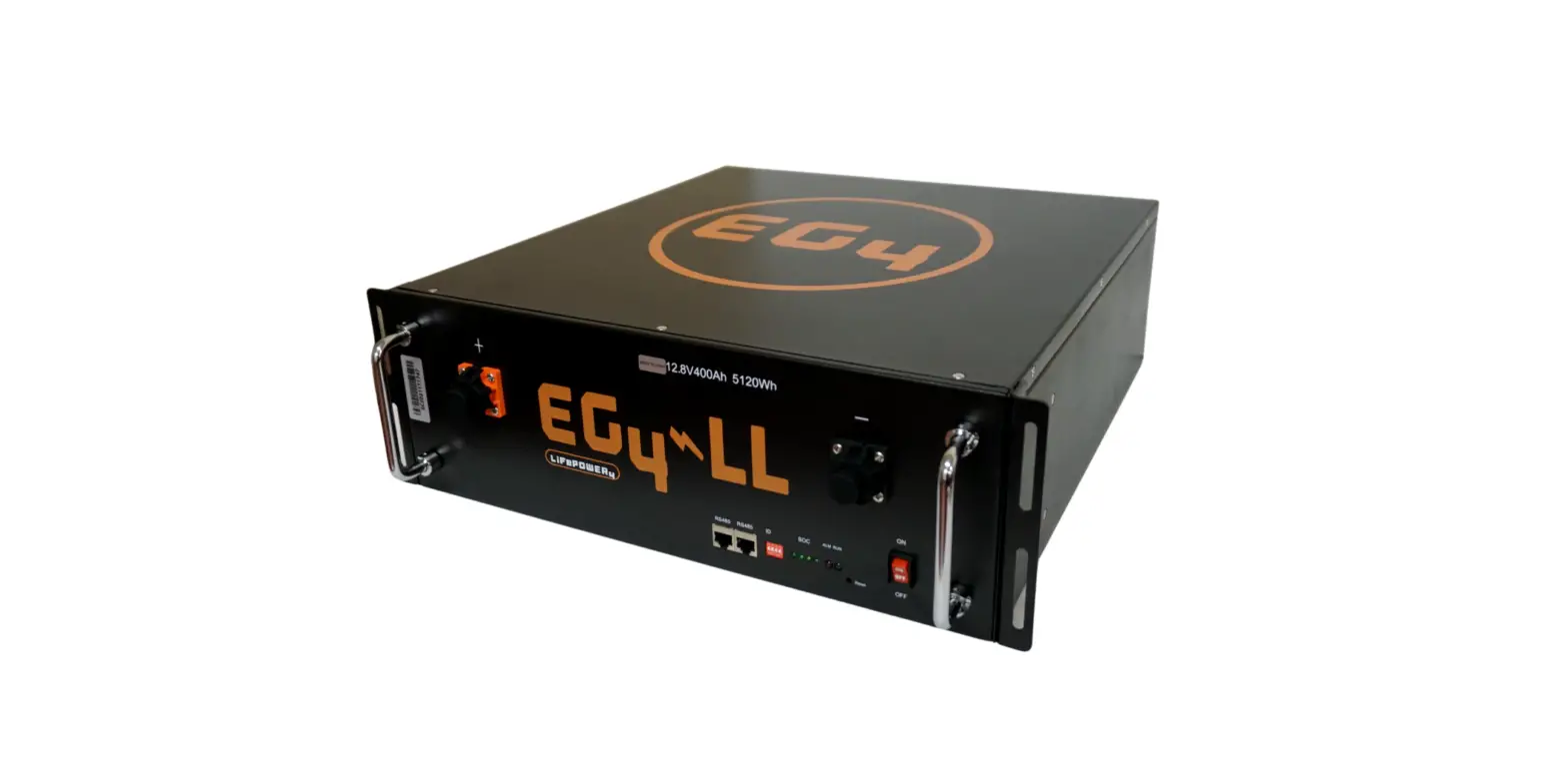
PRODUCT IMAGES (12V/400AH)
PHYSICAL DESCRIPTIONS
| NO. | NAME | FUNCTION | REMARKS |
| 1 | Handle | For Carrying, Handling | |
| 2 | Terminals | Power Line Connection | |
| 3 | Fixture | installed | |
| 4 | ID | Assign Dip Switch | See Next Chart |
| 5 | RUN | LED On/Off | Indicates Operation |
| 6 | RS485 | Communication Port | |
| 7 | On / Off Switch | On / Off Switch | |
| 8 | ALM | LED Alarm | |
| 9 | SOC | State of Charge | 4 lights full charge |
| 10 | DO | Dry Contact | optional |
DIP SWITCH ADDRESS ASSIGNING
| Code | Address | Assign | Remarks | |||
| 1 | 2 | 3 | 4 | |||
| ON | ON | ON | ON | 0 | Model 0 |  |
| ON | ON | ON | OFF | 1 | Modell | |
| ON | ON | OFF | ON | 2 | Modell | |
| ON | ON | OFF | OFF | 3 | Model 3 | |
| ON | OFF | ON | ON | 4 | Model 4 | |
| ON | OFF | ON | OFF | 5 | Models | |
| ON | OFF | OFF | ON | 6 | Model 6 | |
| ON | OFF | OFF | OFF | 7 | Model 7 | |
Note: In the table, code bits are in accordance with the control panel ID code corresponding to the binary digit, dial up stands for “OFF “, dial down stand for ” ON “, the left dial is low digit, the right dial is high digit, encoding in the range of 0~15, which can support up to 16 modules cascade.
BATTERY LED INDICATOR DESCRIPTIONS
| State | Warning/ Normal | RUN | ALM | SOC LED | Definition | |||
| 25% | 50% | 75% | 100% | |||||
| OFF | OFF | OFF | OFF | OFF OFF | OFF | All OFF | ||
| Standby | Normal | ON | OFF | Indicator as the battery capacity | ||||
| Warning | ON | Flash 2 | ||||||
| Protection | OFF | ON | ||||||
| Charge | Normal | Flashi | OFF | |||||
| Warning | Flashi | Flash2 | ||||||
| Protection | OFF | ON | ||||||
| Discharge | Normal | Flash 2 | OFF | |||||
| Warning | Flash2 | Flash2 | ||||||
| Protection | OFF | ON | ||||||
| BMS failure | OFF | Flash2 | OFF | |||||
Note:The SOC means “state of charge”, there are 4 LEDs for SOC. From left to right, each light indicates an increase of 20% SOC
BMS SPECIFICATIONS
BMS provides complete management and protection for your batteries cells. You can expect.
- Voltage Warning and Protection for module and each cell
- Over Charge protection
- Over Discharge Protection
- Current Warning and Protection
- Charging Current Maximums
- Discharging Over Current Protection
- Reverse Polarity Protection
- Temperature Warning and Protection (BMS and Cell Sensors)
- Smart Cell Balancing
- Battery Thermal Preservation
INSTALLATION OVERVIEW
Installation Preparation
Prior to installation ensure that all Load Equipment to be connected to the battery system is in good condition and free from defects. Double check all cabling for exposed wiring, loss of integrity, or poor insulation. Ensure all battery and power systems are reliably grounded. Please double check that all power systems are in the OFF state.
Installation Environment
| TYPE | REQUIREMENT |
| Working Temperature | -4℉ ~ +131 ℉ |
| Storage Temperature | -4℉ ~ +113 ℉ |
| Relative Humidity | <95% |
| Atmospheric Pressure | 86kPa ~ 106kPa |
| Site Requirements | No Conductive Dust / Corrosive Gas. Keep away from Heat and Flame |
Installation Process
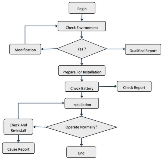
Installation Steps
| State | Type | Indicator | Disposal |
| Charging | Over voltage protection | ALM | Stop charge, check module voltage and charger |
| Over current protection | ALM | Stop charge, check the settings and limitation | |
| Temperature protection | ALM | Stop charge, wait for the temp recovery | |
| Discharging | Low voltage protection | ALM | Stop discharge, turn to charging mode |
| Over current protection | ALM | Stop discharge, check if there is an over load | |
| Temperature protection | ALM | Stop discharge, wait for the temp recovery |
Ensure that Inverter and Solar Equipment is powered off, as well as Battery Bank is powered off.
Installation of Mounting Lugs – Equipment will be fixed to rack or mounting bracket by the chassis mounting lugs, before the installation of equipment, fix the mounting lugs on both sides of the battery box, ensure that the installation is strong and stable.
Battery Rack Installation – Module mounted in the rack 19 inch ( or cabinet ), when installed use portable handles to arrange in parallel on the frame ( or cabinet ) use the supporting plates within the rack ( or cabinet ), ensure the mounting lugs and frame ( or cabinet ) edge securing with screw into the rack to the mounting holes to ensure that the battery pack mounted solid in the rack.
Ground Battery – use a Grounding cable. The grounding cable ends with a screw. You will fit the chassis rear grounding hole, the other end is connected to the frame ( or cabinet ) grounding copper bar, always double-check to ensure a stable connection.
Power Cable Installation. When using a single battery, battery terminals directly connected to the device or switch power supply terminal, if there are multiple batteries in parallel when in use, please connect all batteries to the copper bus-bar with the power cables.
Connection to Equipment – Connect the copper bus-bar to the charger/load system with power cable to your equipment. ENSURE NOT TO REVERSE POLARIZE!
Communication Cable Installation. When the battery is used in a single, please skip this step. When a plurality of batteries are used in parallel please name each battery based on their dip switches. ( ensure no duplicate address codes are used ), and then connect the communication interface of RS485 one by one. Connect the first or last battery module RS485 interface to the inverter or PC monitor.
After all previous steps have been completed, turn ON each battery module (including their respective output circuit breaker to ON), one at a time, pausing between each to allow the batteries to stabilize. Continue until all battery modules are ON and terminal voltage is detected on the bus bar. If any battery module does not start, or the front panel “ALM” (alarm) lights, or the output circuit breaker goes OFF, immediately turn OFF all battery modules and disconnect the offending battery module from the rack bus bar and remove it from the rack for further inspection. Once all connected battery modules are deemed functioning properly, then turn ON or enable power sources and loads, one at a time, while monitoring the battery modules, sources, and loads for any anomalies. If any battery module front panel “ALM” (alarm) lights, or any circuit breaker trips, or fuses blow, or arcing, or smoke, immediately turn OFF all battery modules, sources, and loads and correct the fault before proceeding.
Caution: If you have any questions about the installation, stop and contact technical support to avoid damage or accidents.
PC SOFTWARE OVERVIEW
Software Menu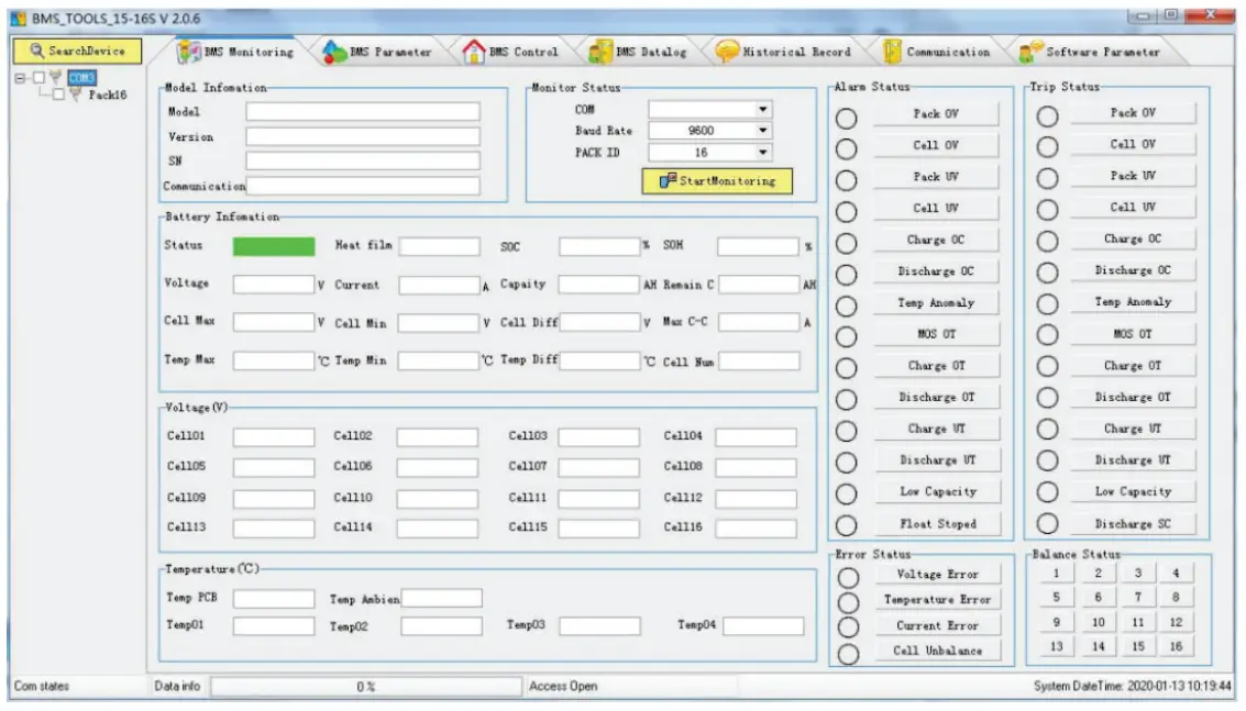
| Menu | Explanation |
| BMS Monitoring | Battery BMS information, display battery data and status |
| BMS control | Control BMS status |
| BMS parameter | Check and set battery parameter |
| BMS Datalog | BMS status storage and export |
| Historical record | History storage and export |
| Communication | real-time data, communication with battery BMS Software settings and Language settings |
| Software parameter |
SOFTWARE INSTALLATION
Unzip the software
Start the Software
Connect the battery communication port with the communication cable(DB9 interface or RS485 interface).
Set the baud rate to 9600.
Click “Search Device”, and the battery BMS will be online automatically.
Then all the battery data can be displayed on the PC software.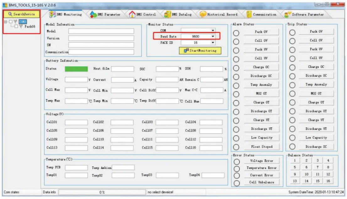
Shipping and Storage of Battery
Shipping
According to the provisions of the product, it can be used in general means of conveyance. Please avoid throwing and/or dropping the battery, keep out of rainfall and strong radiation. Ensure the environment is not prone to corrosion During transportation, please prevent any collisions or strong vibrations of the battery bank.
Storage
Store device indoors with an ambient air temperature between 32F to + 113F, the average monthly relative humidity never exceeding 90%, the ambient air must be free of corrosive, flammable, and explosive gas; storage within warehouse should be ventilated, free of alkaline, acidic substances, and other corrosive gases. Please ensure the battery is removed from repetitive, strong mechanical vibrations, shock, and outside of strong electromagnetic fields and direct sunlight.
WARNINGS:
When the ALM lights up the battery has been alarmed or protected, please check fault reasons and take corresponding measures. Table below states the main alarm conditions.
| State | Type | Indicator | Disposal |
| Charging | Over voltage protection | ALM | Stop charge, check module voltage and charger |
| Over current protection | ALM | Stop charge, check the settings and limitation | |
| Temperature protection | ALM | Stop charge, wait for the temp recovery | |
| Discharging | Low voltage protection | ALM | Stop discharge, turn to charging mode |
| Over current protection | ALM | Stop discharge, check if there is an over load | |
| Temperature protection | ALM | Stop discharge, wait for the temp recovery |
Common Faults
| NO. | Fault phenomenon | Analysis | Solution |
| 1 | No DC output | Low voltage protection | Charge the battery and try again |
| 2 | Power supply time is too short | Battery capacity lack or not full power | Maintenance or replacement |
| 3 | Battery can not be charged to full | Power system DC output voltage falls below the minimum charge voltage | Regulating DC output voltage of power supply to battery suitable charging voltage |
| 4 | ALM LED always lights | Power line connection short circuit | Disconnect the power cable and check all cables |
| 5 | The battery output voltage is unstable | Battery management system do not operate normally | Press the reset button to reset the system, then reboot the system |
| 6 | Communication lost or data fault | Communication settings fail | Check the communication settings and correct it |
Safety Symbols
| Symbol | Definition |
 | Important safety information will follow. |
| DO NOT dispose of battery in a fire. | |
 | Recycle or dispose of Lithium batteries in accordance with local Laws/regulations. |
 | DO NOT dispose of battery in the trash. |
 |
Precautions
Please read and comply with the following conditions of installation and use of the battery, incorrect installation using the battery may cause personal injury or damage to the product.
- DO NOT throw the battery into water. Store batteries in cool and dry environment when not in use.
- DO NOT put the battery into fire or heat the battery, so as to avoid explosion or other dangerous events.
- When charging the battery please choose specialized charging equipment, and follow the correct procedures, do not use unqualified chargers.
- DO NOT reverse positive and negative terminals, do not connect the battery directly to AC power to avoid battery short circuit.
- DO NOT use batteries from different manufacturers or different kinds, types together ,and do not mix old batteries and new batteries.
- DO NOT use the battery when it becomes hot, bulges, deforms or leaks.
- DO NOT puncture the battery by nail or other sharp objects; Do not throw, stamp on, impact or hit the battery.
- DO NOT open or try to repair the battery when it is defective. Warranty invalid if the battery repaired or disassembled.
- Batteries are 75% charged before shipment, Don’t use the battery if it’s hot, bulged, or smells abnormal and so on, and report to the after sale dept. immediately.
- If you need storage the battery for a long time, please charge and discharge the battery every three months to ensure the best performance, and the best state of charge for storage is between 50%~60%.
- Please use the battery in the temperature range which is defined in the manual.
- The state of charge of batteries is 50% before shipment, please charge the battery before using.


