![]() Digital Dimmer Install
Digital Dimmer Install
Instructions
(Part #’s: 21030)
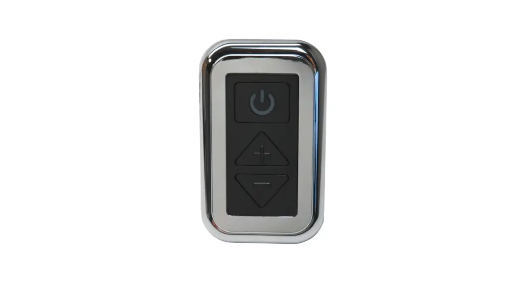
21030 Digital Dimmer
PARTS / TOOLS NEEDED:
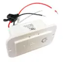 | 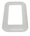 |  |  | 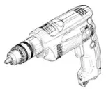 |
| Dimmer Switch | Switch Cover Plate | Mounting Screws | Power Drill | Butt Splices (not provided) |
Safety Instructions
- Disconnect power before installing, adding or changing any component.
- To avoid a hazard to children, account for all parts and destroy all packing materials.
- Do not install any luminaire assembly closer than 6” from any combustible materials.
- Positive (+) outputs require a fuse if the attached wire leads are not rated to handle the max current.
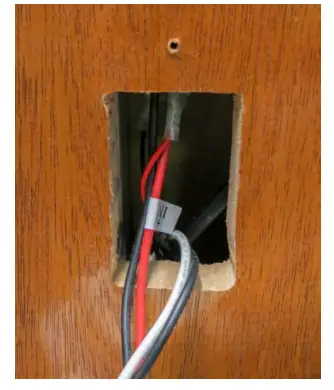
- Determine the installation location and cut a 1-3/8” x 2-5/8” hole. Pull the wiring through.

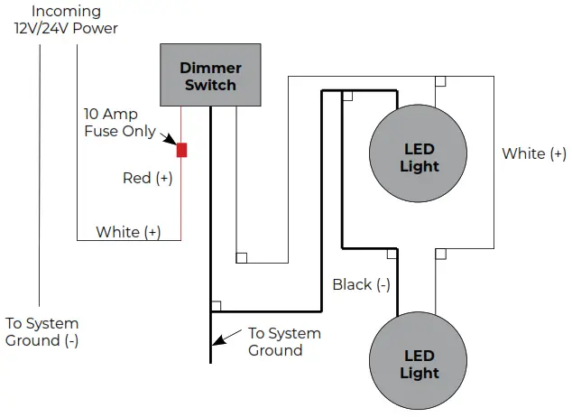
- Wire the switch based on the wiring diagram below.

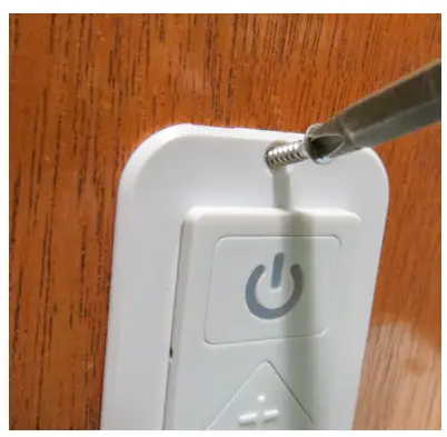
- Push wires and switch into the hole and attach using the screws provided.

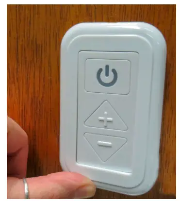
- Snap the cover plate onto the switch by placing top of the plate over the top of the switch and snap at the bottom by pushing in on a plate. Test switch.
To provide a smooth up and down dimming level transition, the switch should be pushed and held. The dimmer will maintain the
pre-set light level when turned off and will return to the same setting once the light is turned on again.
Note: A standard rectangular open-face plate can be used in place of the cover plate.
For warranty information please visit www.itc-us.com
3030 Corporate Grove Dr • Hudsonville • MI • 49426
Phone: 616-396-1355 • www.itc-us.com • [email protected] • DOC#: 710-00083 Rev D • 09/06/22


