![]() INSTALLATION INSTRUCTIONS
INSTALLATION INSTRUCTIONS
FOR P8143-609-L
P8143-609-L Discovery LED Pendant Light
WARNING! SHUT POWER OFF ATFUSE OR CIRCUIT BREAKER.
HANGING THE FIXTURE
- Carefully remove the fixture from the carton and check that all parts are included as shown in the illustration.
- Shut off power at the circuit breaker and remove old fixture including the mounting hardware
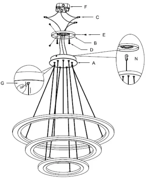
SUGGESTED INSTALLATION (Fig. 1) - Attach the mounting plate (B) to the junction box (F) using screws (D) (Screw Size: 8-32*1/2”L). The side of the mounting plate marked “GND” must face out.
- The support cable (N) is provided to support the weight of the fixture while wiring. Attach the hook on support cable (N) to the slot hole on the mounting plate (B).
Carefully allow the support cable (N) to support the weight of the fixture while wiring.
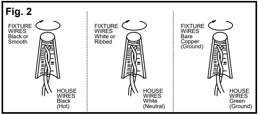
CONNECTING THE WIRES (Fig. 2) - Connect the driver input wire with housing wire as shown in Fig.2, making sure that all wire connectors (C) are secured.
- If your outlet box has a green or bare copper ground wire, connect the fixture’s ground wire to it. Otherwise, connect the fixture’s ground wire directly to the mounting plate (B) using the green screw provided. After wires are connected, tuck them carefully inside the junction box (F).
COMPLETING THE INSTALLATION (Fig. 1) - Connect the canopy (A) with the mounting plate (B) and secure with mounting screws (E).
- Adjust the length of the cable to pull or push until the desired length by pushing down the nod(G).
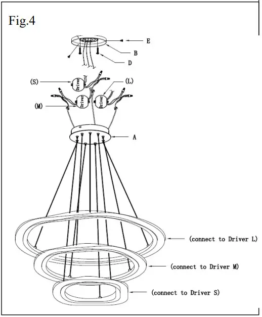
Replacing LED module (Fig. 3&4)
The LED module can be replaced by a qualified electrician without cutting of wire and without damage to any decorative element to which the fixture is attached.
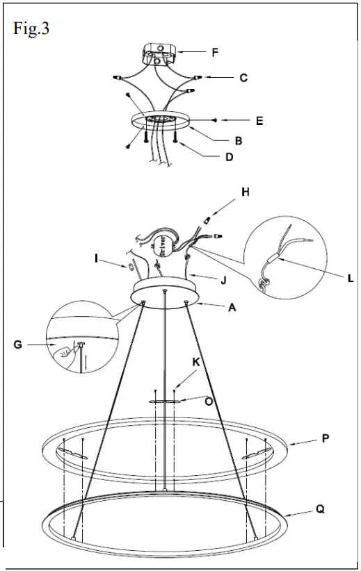
a. Shut off power. Loosen screw (E) to disconnect the canopy (A) from the mounting plate (B)
b. Disconnect the wire connectors (H) from the driver and remove the protective rubber tube (L) on the wire.
c. Loosen the wire clip (I).
d. Pushing down the nod (G) and pull the cable out.
e. Loosen screws (K) and metal clip (O) to disconnect the aluminum ring (Q) (included LED module) from the acrylic ring (P).
f. Reverse steps a-e for installing the new aluminum ring (Q) and make sure that all wire connectors (H) are secured and with electronic tape for insulation. Connect the wires of the largest aluminum ring to output wires from the driver (L), as following middle aluminum ring to driver (M) and the smallest aluminum ring to driver (S) as shown in Fig.4
Note: The LED module should be provided by a specified supplier.
Fig.1
Set# A-021-197
- Mounting plate
- Ground screw
- Mounting screws*2pcs
Your installation is now complete. Return power to the junction box and test the fixture.
IMPORTANT: Fixture should be installed by a qualified electrician to ensure proper wiring and installation.
Dimmable with ELV and/or LED compatible wall dimmer switches.
![]() american lighting association
american lighting association


