![]() VP-427X1
VP-427X1
Quick Start Guide
This guide helps you install and use your VP-427X1 for the first time.
Go to www.kramerav.com/downloads/VP-427X1 to download the latest user manual and check if firmware upgrades are available.
 https://de2gu.app.goo.gl/jM4Dea9DrByB1bveA
Step 1: Check what’s in the box
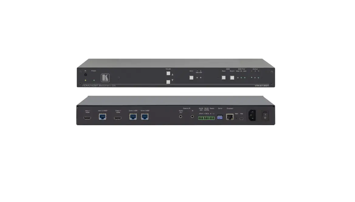
![]() VP-427X1 4K HDBT/HDMI Receiver/Scaler
VP-427X1 4K HDBT/HDMI Receiver/Scaler![]() 1 Power adapter and cord
1 Power adapter and cord![]() 2 Bracket sets
2 Bracket sets![]() 4 Rubber feet
4 Rubber feet![]() 1 Quick start guide
1 Quick start guide
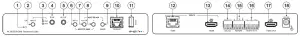
Step 2: Get to know your VP-427X1
Feature | Function | ||
| 1 | ON LED | Lights green when device is powered by power supply or PoE (PD). | |
| 2 | INPUT Select Button | Press to select the input (HDBT or HDMI). | |
| 3 | INPUT LEDs | HDBT | Lights blue when the HDBT input is selected. |
| HDMI | Lights blue when the HDMI input is selected. | ||
| 4 | IR IN 3.5mm Mini Jack | Connect to an IR sensor to control a remote device connected to the transmitter side via HDBT tunneling. | |
| 5 | IR OUT 3.5mm Mini Jack | Connect to an external IR emitter to control a local device from the transmitter side. | |
| 6 | MENU Button | Press to enter/exit the on-screen display (OSD) menu. Press together with the button to reset the output to 1080p resolution. | |
| 7 | ENTER Button | In OSD, press to choose the highlighted menu item. Press together with the FREEZE/+ button to reset the output to XGA resolution (1024×768). | |
| 8 | — Button | In OSD, press to move back through menus or decrement parameter values. Press together with the MENU button to reset the output to 1080p resolution. | |
| 9 | FREEZE/+ Button | In OSD, press to move forward through menus or increment parameter values. When not in OSD, press to freeze the display. | |
| 10 | Ethernet RJ-45 Connector | Connect to a PC via a LAN to setup and monitor the VP-427X1 via the Windows software, as well as upgrade the firmware. | |
| 11 | PROG USB Connector | Connect to a USB stick to perform firmware upgrades. | |
| 12 | INPUTS | HDBT RJ-45 Connector with PoE (PD) | Connect to a transmitter (for example, the Kramer TP-789Txr). |
| 13 | HDMI Connector | Connect to an HDMI source. | |
| 14 | RS-232 CONTROL 3-pin Terminal Block Connector | Connect to a serial controller or PC. | |
| 15 | REMOTE Contact-Closure 4-pin Terminal Block Connector | Connect to contact closure switches, an occupancy sensor and/or toggle switches (contact between the desired pin and GND pin), to turn display on or off (see Step 6: Operate VP-427X1). | |
| – | |||
| 16 | AUDIO 5-pin Terminal Block Connector | Connect to a balanced stereo audio acceptor. | |
| 17 | HDMI OUT Connector | Connect to an HDMI acceptor. | |
| 18 | 12V DC Connector | Connect to the supplied power adapter. | |
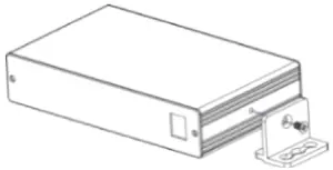
Step 3: Mount VP-427X1
Install VP-427X1 using one of the following methods:
- Attach the rubber feet and place the unit on a flat surface.
- Fasten a bracket (included) on each side of the unit and attach it to a flat surface (see www.kramerav.com/downloads/VP-427X1).
- Mount the unit in a rack using the recommended rack adapter (see www.kramerav.com/product/VP-427X1).

- Ensure that the environment (e.g., maximum ambient temperature & air flow) is compatible for the device.
- Avoid uneven mechanical loading.
- Appropriate consideration of equipment nameplate ratings should be used for avoiding overloading of the circuits.
- Reliable earthing of rack-mounted equipment should be maintained.
- Maximum mounting height for the device is 2 meters.

Step 4: Connect inputs and outputs
Always switch OFF the power on each device before connecting it to your VP-427X1. 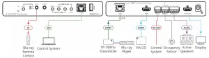
Connecting the audio output
To a balanced stereo audio acceptor: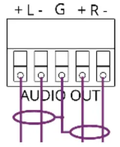
To an unbalanced stereo audio acceptor: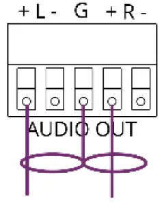
Wiring the RJ-45 Connectors
This section defines the TP pinout, using a straight pin-to-pin cable with RJ-45 connectors.
![]() For HDBT cables, it is recommended that the cable ground shielding be connected/soldered to the connector shield.
For HDBT cables, it is recommended that the cable ground shielding be connected/soldered to the connector shield.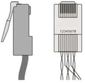
| EIA /TIA 568B | |
| PIN | Wire Color |
| 1 | Orange / White |
| 2 | Orange |
| 3 | Green / White |
| 4 | Blue |
| 5 | Blue / White |
| 6 | Green |
| 7 | Brown / White |
| 8 | Brown |
![]() To achieve specified extension distances, use the recommended Kramer cables available at www.kramerav.com/product/VP-427X1. Using third-party cables may cause damage!
To achieve specified extension distances, use the recommended Kramer cables available at www.kramerav.com/product/VP-427X1. Using third-party cables may cause damage!
Step 5: Connect power
If there is no PoE input, connect the power adapter to the VP-427X1 and plug it to the mains electricity.
Safety Instructions (See www.kramerav.com for updated safety information)
![]() Caution:
Caution:
- For products with relay terminals and GPI\O ports, please refer to the permitted rating for an external connection, located next to the terminal or in the User Manual.
- There are no operator serviceable parts inside the unit.
![]() Warning:
Warning:
- Use only the power cord that is supplied with the unit.
- Disconnect the power and unplug the unit from the wall before installing.
Step 6: Operate VP-427X1
To operate VP-427X1, use one of these options:
- Front panel buttons.
- Remotely, by RS-232 serial commands transmitted by a touch screen system, PC, or other serial controller
- Embedded web pages via the Ethernet.
| RS-232 Control / Protocol 3000 | |||||
| Baud Rate: | 115,200 | Parity: | None | Stop Bits: | 1 |
| Data Bits: | 8 | Command Format: | ASCII | ||
| Example: (Route video HDBT INPUT to HDMI OUTPUT): #ROUTE 1,1,1<CR> | |||||
| Default Ethernet Parameters | |||
| IP Address: | 192.168.1.39 | UDP Port #: | 50000 |
| Subnet Mask: | 255.255.0.0 | TCP Port #: | 5000 |
| Gateway: | 0.0.0.0. | Default Username/password: | Admin/Admin |
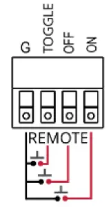
Operating via the remote control switches
Momentarily connect the desired pin to the GND pin to select an input:
| Pin Name | Function |
| TOGGLE | One button toggles between display on and display off (instead of using two separate buttons for on and off). Alternatively, using the VP-427X1 OSD, configure turning the display on or off according to whether a switch is open or closed, for example, when using an occupancy sensor. |
| OFF | Turn off the display. |
| ON | Turn on the display. |