
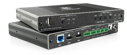
KRAMER KIT-400 Switchable 4K HDBaseT Transmitter/Receiver
This guide helps you install and use your KIT-400 for the first time. Go to www.kramerav.com/downloads/KIT-400 to download the latest user manual and check if firmware upgrades are available.
Check what’s in the box
- KIT-400, including:
- 2 Bracket sets
- 1 Power adapter and cord
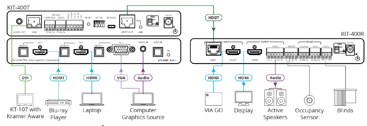
- KIT-400T 4K HDMI/PC Auto Switcher Transmitter and KIT-400R 4K HDBT/HDMI Receiver/Scaler
- 8 Rubber feet
- 1 Quick start guide
Get to know your KIT-400
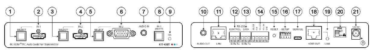
KIT-400T
| # | Feature | Function | |
| 1 | IN 1 | SELECT Button | Press to select the IN 1 input. Lights red when the analog audio is selected; lights green when the embedded audio is selected. |
| 2 | HDMI Connector | Connect to an HDMI source. | |
| 3 | IN 2 | SELECT Button | Press to select the IN 2 input. Lights red when the analog audio is selected; lights green when the embedded audio is selected. |
| 4 | HDMI Connector | Connect to an HDMI source. | |
| 5 | IN 3 | SELECT Button | Press to select the IN 3 input. Lights red when the analog audio is selected; lights green when embedded audio from embedded HDMI is selected, see Step 4: Connect inputs and outputs. |
| 6 | 15-pin HD Connector | Connect to a PC graphics source. | |
| 7 | AUDIO IN 3.5mm Mini Jack | Connect to an unbalanced, stereo audio source (for example, the audio output of the laptop). | |
| 8 | IN 4 (REMOTE) Button | Press to select the inputs on KIT-400R: · Button lights – HDMI INPUT on KIT-400R is selected as the input. · Button off – The selected input on KIT-400T is routed via HDBT. | |
| 9 | ON LED | Lights green when the device is powered by a power adapter; lights red when power is provided via PoC. | |
| 10 | AUDIO OUT 3.5mm Mini Jack | Connect to the unbalanced, stereo audio acceptor (for example, active speakers). | |
| 11 | LAN RJ-45 Connector | Connect to the LAN (Ethernet traffic or PC controller). | |
| 12 | RS-232 | CONTROL 3-pin Terminal Block Connector | Connect to a serial controller or PC. |
| 13 | DATA 3-pin Terminal Block Connector | Connect to a serial data source or acceptor. | |
| 14 | Remote Contact-closure 4-pin Terminal Block Connector | Connect to contact closure switches (by momentary contact between the desired pin and GND pin) to select an input, the remote IN 4 and audio volume (up or down), see Step 6: Operate KIT-400. | |
| 15 | RESET Button | Short press: sends a reset command to KIT-400R and then reboots KIT-400T. Long press: resets KIT-400R to its factory default parameters and then resets KIT-400T to its factory default parameters. | |
| # | Feature | Function |
| 16 | SETUP 4-way DIP-switch | Set the device behavior, see Step 4: Connect inputs and outputs. |
| 17 | SERVICE Mini USB Connector | Connect to a PC to perform a firmware upgrade. |
| 18 | HDBT OUT RJ-45 Connector | Connect to KIT-400R. |
| 19 | LINK LED | Lights blue when a link is established with the receiver. |
- Follow powering instructions in Step 5: Connect power.
- Failure to use PoC and power connector correctly may destroy the devices!
20 PoC (Power over Cable) Switch Set the PoC switch to ON on both KIT-400T and KIT-400R. 21 12V DC Connector Connect to the supplied power adapter, unless the power adapter is connected to KIT-400R.
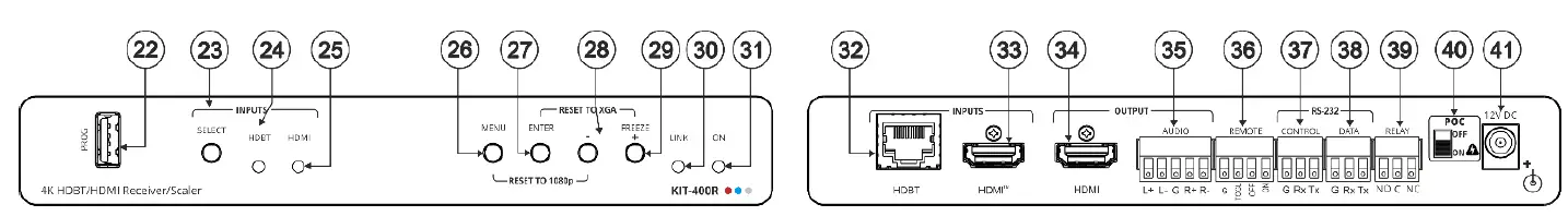
KIT-400R
| # | Feature | Function | |
| 22 | PROG USB Connector | Connect to a USB stick to perform firmware upgrades. | |
| 23 | INPUTS | SELECT Button | Press to select the input (HDBT or HDMI). By default, the SELECT button is locked. You can unlock it via the ADVANCED menu in the OSD. |
| 24 | HDBT LED | Lights blue when the HDBT input is selected. | |
| 25 | HDMI LED | Lights blue when the HDMI input is selected. | |
| 26 | MENU Button | Press to enter/exit the on-screen display (OSD) menu. Press together with the – button to reset to 1080p. | |
| 27 | ENTER Button | In OSD, press to choose the highlighted menu item. Press together with the FREEZE/+ button to reset to XGA. | |
| 28 | – | In OSD, press to move back through menus or decrement parameter values. | |
| 29 | FREEZE/+ Button | In OSD, press to move forward through menus or increment parameter values. When not in OSD, press to freeze the display. | |
| 30 | LINK LED | Lights blue when a link is established with the transmitter. | |
| 31 | ON LED | Lights green when device is powered. | |
| 32 | INPUTS | HDBT RJ-45 Connector | Connect to KIT-400T. |
| 33 | HDMI™ Connector | Connect to an HDMI source. | |
| 34 | OUTPUT | HDMI Connector | Connect to an HDMI acceptor. |
| 35 | AUDIO 5-pin Terminal Block Connector | Connect to a balanced stereo audio acceptor. | |
| 36 | REMOTE Contact-Closure 4-pin Terminal Block Connector | Connect to contact closure switches, an occupancy sensor and/or toggle switches (contact between the desired pin and GND pin), to turn display on or off. See Step 6: Operate KIT-400. | |
| 37 | RS-232 | CONTROL 3-pin Terminal Block Connector | Connect to a serial controller or PC. |
| 38 | DATA 3-pin Terminal Block Connector | Connect to a serial data source or acceptor. | |
| 39 | RELAY 3-pin Terminal Block Connector | Connections to the internal relay: Normally open (NO), normally closed (NC), and common (C). Connect to devices to be controlled by relay (for example, a motorized projection screen). | |
- Follow powering instructions in Step 5: Connect power.
- Failure to use PoC and power connector correctly may destroy the devices!
40 PoC (Power Over Cable) Switch Set the PoC switch to ON on both KIT-400T and KIT-400R. 41 12V DC Connector Connect to the supplied power adapter, unless the power adapter is connected to KIT-400T.
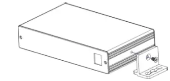
Mount KIT-400
Install KIT-400 using one of the following methods:
- Attach the rubber feet and place the unit on a flat surface.
- Fasten a bracket (included) on each side of the unit and attach it to a flat surface (see www.kramerav.com/downloads/KIT-400).
- Mount the unit in a rack using the recommended rack adapter (see www.kramerav.com/product/KIT-400).

- Ensure that the environment (e.g., maximum ambient temperature & air flow) is compatible for the device.
- Avoid uneven mechanical loading.
- Appropriate consideration of equipment nameplate ratings should be used for avoiding overloading of the circuits.
- Reliable earthing of rack-mounted equipment should be maintained.
- The maximum mounting height for the device is 2 meters.
Connect inputs and outputs
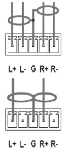
Connecting the audio output
- To a balanced stereo audio acceptor
- To an unbalanced stereo audio acceptor

Wiring the RJ-45 connectors
This section defines the TP pinout, using a straight pin-to-pin cable with RJ-45 connectors. For HDBT cables, it is recommended that the cable ground shielding be connected/soldered to the connector shield. 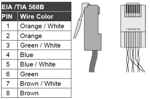
To achieve specified extension distances, use the recommended Kramer cables available at www.kramerav.com/product/KIT-400. Using third-party cables may cause damage!
Setting the KIT-400T DIP-switches
A switch that is down is on; a switch that is up is off. By default, all the switches are up (off). After changing a DIP-switch you must power cycle the device to implement the change.
- DIP-switch 1 set to off (up).
- DIP-switch 2 set to off (up).
Audio Switching Selection
| DIP-switch 3 | DIP-switch 4 | Audio Input Selection |
| Off (up) | Off (up) | Automatic – Priority selection: Embedded HDMI ” analog Audio In (high to low priority). |
| Off (up) | On (down) | Automatic – Priority selection: Analog Audio In ” embedded HDMI (high to low priority). |
| On (down) | Off (up) | Embedded HDMI. |
| On (down) | On (down) | Analog Audio In |
Connect power
To power the devices:
- Set the PoC switches to ON on both devices.
- Connect the power adapter to one of the devices (KIT-400T or KIT-400R).
Safety Instructions (See www.kramerav.com for updated safety information)
Caution:
- For products with relay terminals and GPI\O ports, please refer to the permitted rating for an external connection, located next to the terminal or in the User Manual.
- There are no operator serviceable parts inside the unit.
Warning:
- Failure to use PoC and power connector correctly may destroy the devices!
- Use only the power cord that is supplied with the unit.
Disconnect the power and unplug the unit from the wall before installing it.
Operate KIT-400
Operate KIT-400 via:
- Front panel buttons
- Remotely, by RS-232 serial commands transmitted by a touch screen system, PC, or another serial controller
- Embedded web pages via the Ethernet
- Remote control switches.
- Room Automation Panel.
RS-232 Control / Protocol 3000 Baud Rate: 115,200 Parity: None Data Bits: 8 Command Format: ASCII Stop Bits: 1 Example: (Set the Audio out volume level to 75): #AUD-LVL 1,1,75 Default Ethernet Parameters IP Address: 192.168.1.39 UDP Port #: 50000 Subnet mask: 255.255.0.0 TCP Port #: 5000 Gateway: 0.0.0.0.
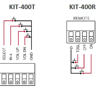
Operating via the remote control switches
Momentarily connect the desired pin to the GND pin to select an input:
| Pin Name | Function |
| KIT-400T | |
| SELECT | Short press – Select the input. Long press – Adjust the VGA phase shift. |
| IN 4 | Select the IN 4 input on KIT-400R. |
| VOL UP | Increase the analog audio output level. Short press – Increase volume by one step. Long Press – Increase the volume from 0 to 100% in 10 seconds. |
| VOL DN | Decrease the analog audio output level. Short press – Decrease volume by one step. Long Press – Decrease the volume from 100% to 0 in 10 seconds. |
| KIT-400R | |
| TOGL | One button toggles between display on and display off (instead of using two separate buttons for on and off). Alternatively, using the KIT-400R OSD, configure turning the display on or off according to whether a switch is open or closed (for example, when using an occupancy sensor). |
| OFF | Turn off the display. |
| ON | Turn on the display. |
Operating via Room Automation Panel
Control KIT-400 via any of Kramer’s touch panels which include the Kramer Aware app (for example, KT-1010).
To operate KIT-400 via room automation panel: 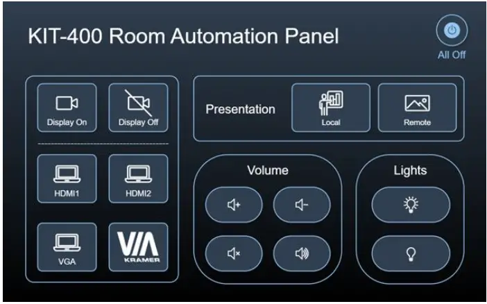
- Open Kramer Aware app on your touch panel.
- Enter KIT-400R IP address. The KIT-400 default control screen appears.
You can change the default control screen configuration via the KIT-400 embedded web pages. Kramer Aware App can be connected to KIT-400 only if password protection (Authentication) is disabled. You can disable authentication via the KIT-400 web page.
The terms HDMI, HDMI High-Definition Multimedia Interface, and the HDMI Logo are trademarks or registered trademarks of HDMI Licensing Administrator, Inc.


