Contents hide

EATON IL159026EN CX Plus
Replacement instructions for CX with CX Plus controller
WARNING
ENSURE THAT THE UPSTREAM AND INTEGRAL (IF INCLUDED) DISCONNECT / OVERCURRENT PROTECTION DEVICE HAS BEEN TURNED OFF AND LOCKED OUT. ALSO ENSURE THE CT WIRES THAT ARE TERMINATED ON TERMINALS TB1–1 AND TB1–2 ARE SHORTED. WAIT AT LEAST 5 MINUTES AFTER DISCONNECTION OF POWER SUPPLY BEFORE OPENING THE ENCLOSURE FOR SERVICE.
CX controller removal
- For catalog option W remove all caulking around the CX controller.
- Remove all wires terminated into the BLR-CX controller, ensuring the wire markers do not become removed.
- Open the enclosure door and lift up/pull the slide tabs toward you to loosen the controller from its enclosure.
- The controller can now be removed by gently pushing the controller away from the enclosure door.
Re energizing the unit
- Once all wiring connections are completed, check all wiring is secured and tight.
- Remove the CT shorting link at TB1 terminals 1 and 2.
- Energize the upstream and/or integral disconnect/overcurrent protection device.
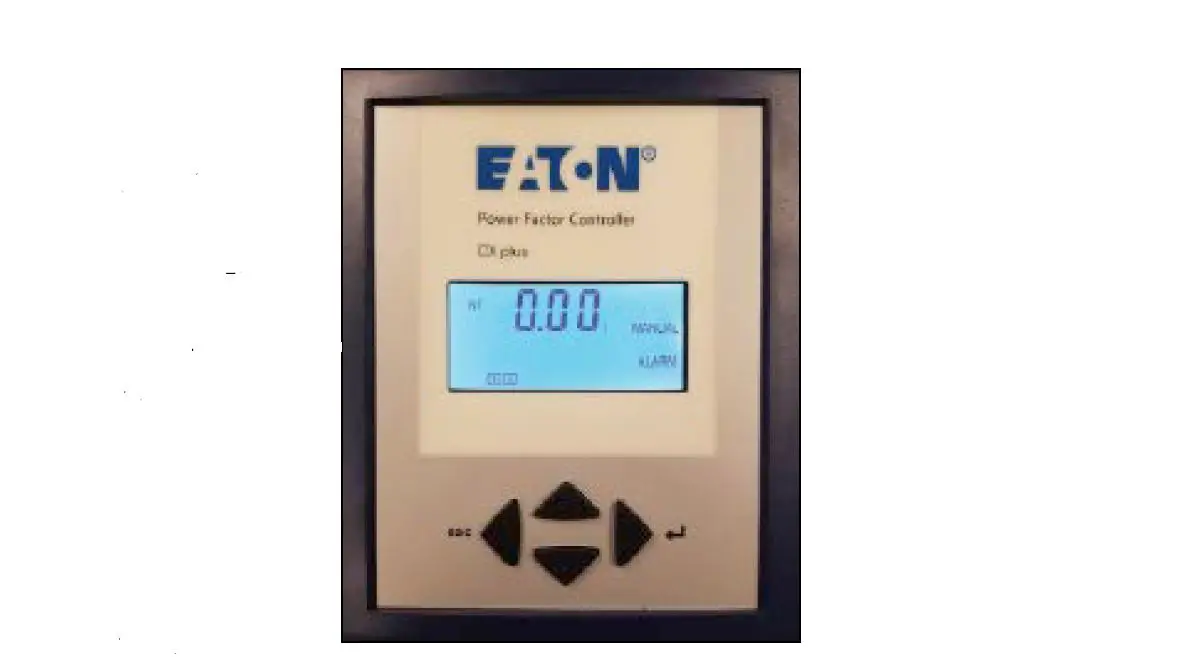
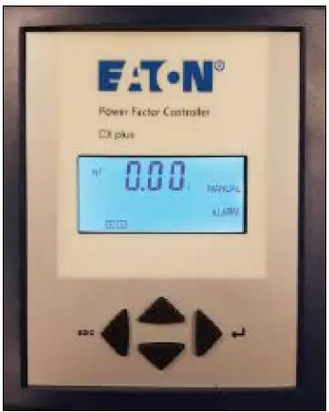
- The CX Plus controller is shown below
CX Plus controller installation
- Place the BLR-CX Plus controller into the slot from the BLR-CX.
- Secure the controller in place using the tab slide-in mechanism (similar to the BLR-CX).
- For catalog option “W”, caulk around the CX Plus controller (between the facia and the door cutout).
- Reconnect all the following wires for UM1, UM2 A through 12, k and 1.
- Note: Output stages 13 and 14 will not have any wires connected to them.
- Remove and discard shorting wires from UM1 and UM2 to Lb (or La) and N.
- If this is an AutoVAR Filter, remove the RTF wire from Lb (CX) and connect it to UM2 (CX Plus).
- For catalog option A, remove the wires from M/MS (CX) and terminate it onto the M/MS terminals of the CX Plus. Wire extension or rewiring from TB may be necessary for this change.
Digital display
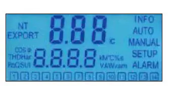
Screen legend
- INFO Capacitor Database.
- AUTO Automatic Mode.
- MANUAL Manual Mode.
- SETUP Setup Mode.
- ALARM Blinking during alarm.
- NT Second target-pf is active.
- EXPORT Export of active energy.
- 1-12 Capacitor stage number indication.
- The CX Plus controller is operated by using four keys
Operational keys
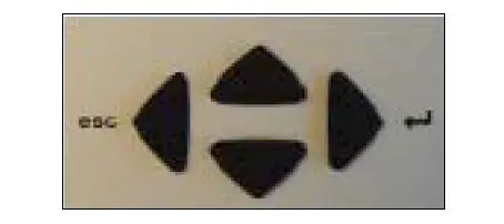
- Press the up or down keys to scroll through submenus.
- Pressing the right key enter allows selection, entering the Edit Mode, or accepts the edited values.
- In the Edit Mode, the left key escape or right key scroll left and right to allow setting of the appropriate digit.
- Outside of Edit Mode, the left key exits to the next higher level.
- Press and hold the left key for approximately 3 seconds to silence any alarms.
- Upon power on the controller displays the existing power factor value X.XX and enters the Automatic Control Mode.
- The I at the end indicates an inductive power factor and would be appropriate for most installations.
- A c at the end indicates capacitive power factor and suggests reactive power export and may not be appropriate.
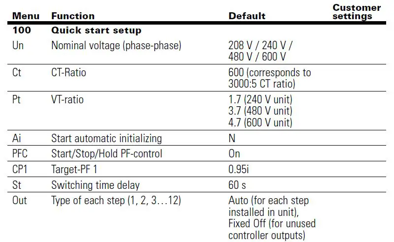
- Set up the basic parameters in the controller.
- From the main screen, press the down key to step through the INFO and SETUP modes.
- When SETUP is shown, press the right key to enter the Menu 100.
- Press the right key and program and/or verify the following values.
- Un :Nominal voltage (factory programmed; customer may verify
- Ct : CT ratio factory set to 600, which corresponds to 3000:5 current transformer ratio. Changing the CT ratio will change the capacitor step sizes in 402 and those values will have to be reprogrammed.
- Pt :PT ratio factory programmed.
- Ai :Start of automatic initialization factory programmed PFC P control ON/OFF/HOLD factory programmed CP1 Target PF customer to program.
- St : Switching time delay factory programmed; customer may verify.
- Out Output type of each stage Auto/Alarm/Fixed Off/Fixed Onfactory programmed; customer may verify.
- Once the Menu 100 is programmed, press the left key three times to return to the main screen that displays the existing PF.
- From the main screen, press the left key to enter the Measurement Mode to verify the measured values. See the menu map for a list of designated parameters.
- Press the left key to return to the main screen that displays the existing PF.
- To verify the capacitor bank is working, activate the controller in Manual Control Mode and cycle through all the available steps. Note: The steps will switch on only after the factory-set capacitor stage discharge time has elapsed.
- After each manual operation of the stage, the PF should change in the right direction for example 0.70 i >> 0.78 i >> 0.85 i.
- If the PF changes in the right direction, the capacitor bank has been correctly commissioned.
- To switch the controller in Manual and Control Mode, press the down key to step through the INFO.
- Press and hold the right key for approximately 3 seconds until 1 displays, indicating the stage number 1 is available for control.
- The controller freezes the stages in their existing state ON, OFF, or HOLD.
- Therefore, it is important to ensure that at the end of this step the controller is returned to the Automatic Control Mode by pressing the left key to return to the main screen that displays the existing PF.
- After activating all available steps, one should make note of the displayed PF values, as that reading should be greater than or equal to the target PF desired.
- If the displayed PF with the electrical system fully loaded and all steps energized is less than the target PF then the selected capacitor bank is not sized adequately to raise the PF to the desired value.
- The customer should either upgrade the capacity of the capacitor bank or the target PF value should be decreased to prevent PF alarms.
Replacement instructions for CX with CX Plus controller
Default settings
| 200 Setup measuring system 201 Nominal voltage phase phase 208 V / 240 V /480 V / 600 V 202 CT-ratio: 600 (corresponds to 3000:5 CT ratio | ||
| 203 VT ratio 1.7(240 V unit) 3.7(480 V unit) 4.7(600 V unit) 204 Tolerance nominal voltage: 20% | ||
| 205 | Voltage measuring | Y = L–L |
| 206 | Phase-offset | 90 |
| 207 | Start automatic initializing | N |
| 208 | Synchronization to frequency | 60 (60 Hz unit) |
| 209 | Temperature offset | 0 °C |
| 300 | Setup control system | |
| 301 | Switching threshold | 55% |
| 302 | Target-PF 1 | 0.95i |
| 303 | Target-PF 2 | 0.95i |
| 304 | Target-PF 2 at KW-export | N |
| 305 | Switching time delay | 60 s |
| 306 | Switching time delay for fine control | 10 s |
| 307 | Fine control active | N for units with equal stage sizes Y for units with multiple stage sizes |
| 308 | Automatic Stage detection | N |
| 309 | Block defective Capacitors | N |
| 310 | Start/Stop/Hold PF-control | On |
| 311 | Control algorithm | 1 |
| 312 | Reactive-power offset | 0 |
| 313 | Asymmetrical switching time delay | 1 |
| 314 | Switch-off capacitors in leading condition | N |
| 315 | Distribute sw. operations | N |
| 316 | Detect faulty stages | Y |
| 400 | Setup capacitor database | |
| 401 | Discharge time | 60 s |
| 402 | Capacitor size: step 1 max. 12 | Varies (see equipment drawings for step size, typically 25, 50, or 100 kvar capacitive |
| 400 | Setup capacitor database continued | |
| 403 | Type of exit: step 1 max. 12 | Auto for each step |
| installed in unit | ||
| Fixed Off for unused | ||
| controller outputs | ||
| 404 | Switching operations: step 1 max. 12 | 0 |
| 405 | Operations hours counter: step 1 max 12 | 0 h |
| 406 | Fan relay as stage output | N |
| 500 | Setup alarm system | |
| 501 | Reset alarms manually | N |
| 502 | THD U threshold | 6% |
| 503 | Disconnect capacitors when THD > | N |
| 504 | THD alarm delay | 120 s |
| 505 | Stop control if I=0 | N |
| 506 | Service alarm | N |
| 507 | Max. operations per step | 262 k |
| 508 | Max. operation hours of BLR-ACX-V | 65.5 k |
| 509 | Max. operation hours per step | 65.5 k |
| 510 | THD-I threshold | 20% |
| 511 | Digital input logic | Y |
| 512 | Temp. threshold level 1 (fan control, type of exit: AL) | 40 °C |
| 513 | Temp. threshold level 2, disconnect capacitors | 55 °C |
| 514 | Control alarm (target cannot be reached) | Y |
| 515 | Faulty stages alarm | Y |
| 516 | Stage power loss alarm | Y |
| 517 | Flashing display | N |
| 518 | Digital input function | CP2 |
| 519 | I Low alarm suppr. | Y |
| 520 | Switch off active stages if digital input alarm | N |
| 521 | I Low alarm | Y |
| 522 | I High alarm delay | 10 s |
| 523 | Switch off interval | 60 s |
| 600 | Reset | |
| 601 | Reset to default values | N |
| 602 | Reset capacitor database to default | N |
| 603 | Reset operation hours | N |
| 604 | Reset average PF | N |
| 605 | Reset max. temperature | N |
| 606 | Reset alarm | N |
| 607 | Info firmware | |
| 608 | Change password | 242 |
| 609 | Restart first setup | N |
| 700 Modbus Baud rate | 19.2 k | |
| Parity and stop bits | EVEN | |
| Slave address | 1 | |
| 800 | System | |
| 801 | Backlight during commissioning mode | N |
| 802 | Backlight delay time | 0.25 h |


