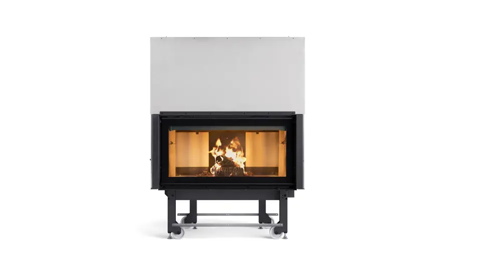
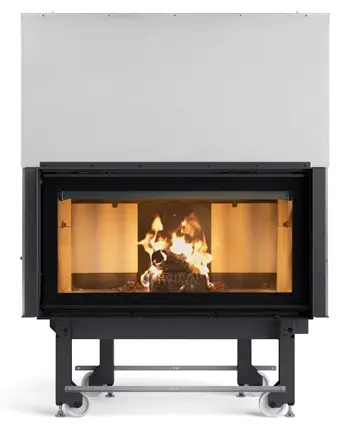
La Nordica MONOBLOCCO 1000 EVOWood Fireplaces
Product Information
Product Usage Instructions
| ATTENTION | |
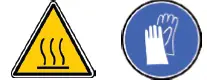 | SURFACES CAN BECOME VERY HOT! ALWAYS USE PROTECTIVE GLOVES! |
SAFETY
- THE APPLIANCE MAY BE USED BY CHILDREN 8 YEARS OF AGE OR OLDER AND INDIVIDUALS WITH REDUCED PHYSICAL, SENSORY, OR MENTAL CAPACITIES OR WITHOUT EXPERIENCE OR THE NECESSARY KNOWLEDGE, PROVIDED THAT THEY ARE SUPERVISED OR HAVE
- RECEIVED INSTRUCTIONS ON SAFE USE OF THE APPLIANCE AND THAT THEY UNDERSTAND THE INHERENT DANGERS.
- THE GENERATOR MUST NOT BE USED BY PERSONS (INCLUDING CHILDREN) WITH REDUCED PHYSICAL, SENSORY AND MENTAL CAPACITIES OR WHO ARE UNSKILLED PERSONS, UNLESS THEY ARE SUPERVISED AND TRAINED REGARDING USE OF THE APPLIANCE BY A PERSON RESPONSIBLE FOR THEIR SAFETY.
- THE CLEANING AND MAINTENANCE REQUIRED BY THE USER MUST NOT BE PERFORMED BY CHILDREN WITHOUT SUPERVISION.
- CHILDREN MUST BE CHECKED TO ENSURE THAT THEY DO NOT PLAY WITH THE APPLIANCE.
- DO NOT TOUCH THE GENERATOR WHEN YOU ARE BAREFOOT OR WHEN PARTS OF THE BODY ARE WET OR DAMP.
- IT IS FORBIDDEN TO MODIFY THE APPLIANCE IN ANY WAY.
- DO NOT PULL, DISCONNECT, TWIST ELECTRIC CABLES (WHERE EXISTING) LEAVING THE PRODUCT, EVEN IF DISCONNECTED FROM THE ELECTRIC POWER SUPPLY MAINS.
- THE POWER SUPPLY PLUG MUST BE ACCESSIBLE AFTER INSTALLATION.
- DO NOT CLOSE OR REDUCE THE DIMENSIONS OF THE AIRING VENTS IN THE PLACE OF INSTALLATION. THE AIRING VENTS ARE ESSENTIAL FOR CORRECT COMBUSTION.
- DO NOT LEAVE THE PACKAGING ELEMENTS WITHIN REACH OF CHILDREN OR UNASSISTED DISABLED PERSONS.
- THE HEARTH DOOR MUST ALWAYS BE CLOSED DURING NORMAL FUNCTIONING OF THE PRODUCT.
- WHEN THE APPLIANCE IS FUNCTIONING AND HOT TO THE TOUCH, ESPECIALLY ALL EXTERNAL SURFACES, ATTENTION MUST BE PAID
- CHECK FOR THE PRESENCE OF ANY OBSTRUCTIONS BEFORE SWITCHING THE APPLIANCE ON FOLLOWING A PROLONGED PERIOD OF INACTIVITY.
- THIS APPLIANCE MUST NOT BE USED TO BURN WASTE
- DO NOT USE ANY FLAMMABLE LIQUIDS FOR IGNITION
- THE MAJOLICAS (WHERE EXISTING) ARE TOP QUALITY ARTISAN PRODUCTS AND AS SUCH CAN HAVE MICRO-DOTS, CRACKLES AND CHROMATIC IMPERFECTIONS. THESE FEATURES HIGHLIGHT THEIR VALUABLE NATURE. DUE TO THEIR DIFFERENT DILATION COEFFICIENT, THEY PRODUCE CRACKLING, WHICH DEMONSTRATE THEIR EFFECTIVE AUTHENTICITY. TO CLEAN THE MAJOLICAS, IT IS RECOMMENDED TO USE A SOFT, DRY CLOTH. IF A DETERGENT OR LIQUID IS USED, THE LATTER COULD PENETRATE INSIDE THE CRACKLES, HIGHLIGHTING THEM.
GENERAL PRECAUTIONS
DECLARATION OF CONFORMITY OF THE MANUFACTURER
INSTALLATION REGULATIONS
- Canalization of the warm air (see cap. CANALIZATION).
- Verify if your structure can support the weight of the appliance. In case of insufficient carrying capacity it is necessary to adopt appropriate measures, La NORDICA responsibility is limited to the supply of the appliance (See chapter TECHNICAL DESCRIPTION).
- Make sure that the floor can support the weight of the appliance, and if it is made of flammable material, provide suitable insulation (DIMENSIONS ACCORDING TO REGIONAL REGULATIONS).
- Make sure that there is adequate ventilation in the room where the appliance is to be installed.
- DO NOT INSTALL THE APPLIANCE IN ROOMS CONTAINING COLLECTIVE VENTILATION DUCTS, HOODS WITH OR WITHOUT EXTRACTOR, TYPE B GAS APPLIANCES, HEAT PUMPS, OR OTHER APPLIANCES THAT, OPERATING AT THE SAME TIME, CAN PUT THE ROOM IN DEPRESSION (ref. UNI 10683 standard)
- Make sure that the flue and the pipes to which the appliance will be connected are suitable for its operation. It is NOT allowed the connection of various appliances to the same chimney.
- The diameter of the opening for connection to the chimney must at least correspond to the diameter of the flue gas pipe. The opening must be equipped with a wall connection for the insertion of the exhaust pipe and a rosette.
FIRE-FIGHTING SAFETY MEASURES
FIRST-AId MEASURES
- should any fire arise in the stack or in the flue:
- close the feeding door.
- close the registers of combustion air
- extinguish the fire using carbon dioxide fire-fighting means (co2 dust).
- seek immediate intervention of fire brigade.
DESCRIPTION
| accessories | SERIES | Optional |
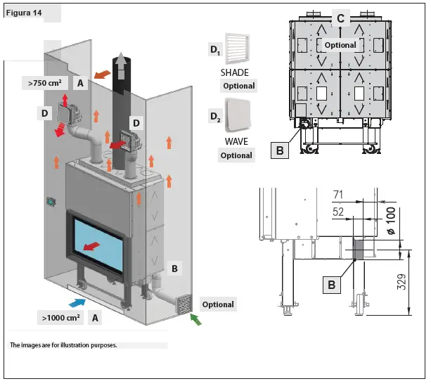
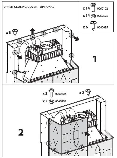
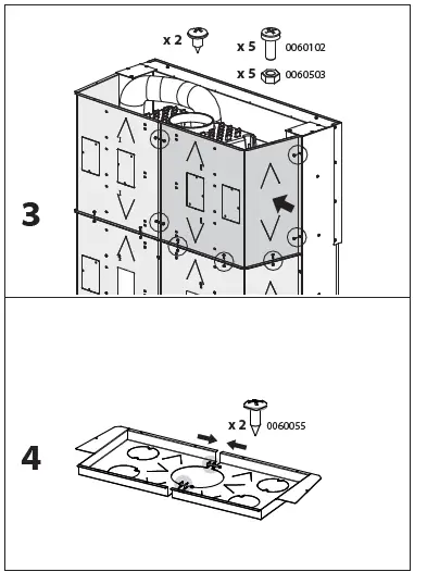
| GLOVE | upper closings cover Picture 13– C – Picture 14 – C | |
| POKER | Kit – wind air (ducted air) Picture 14 | |
| air vents mod. shade (ducted air) Picture 14 – D2 | ||
| air vents mod. wave (ducted air) Picture 14 – D1 |
| hourly consumption (kg/h) | Combustion air | Tertiary airs | |
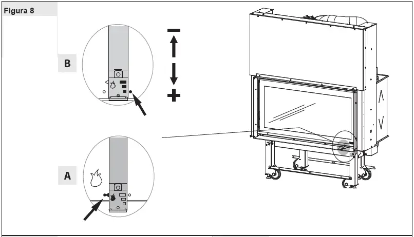
| monoblocs 1300 evo | 3,4 | Picture 8 – b | pre-adjusted |
FLUE
- Essential requirements for a correct operation of the device:
- the internal section must be preferably circular;
- be thermally insulated and water-proof and produced with materials suitable to resist to heat, combustion products and possible condensates;
- not be throttled and show a vertical arrangement with deviations not greater than 45°;
- if already used, it must be clean;
- all the sections of the flue gas duct must be accessible to inspection;
- inspection openings must be provided for cleaning.
- observe the technical data of the instructions manual;
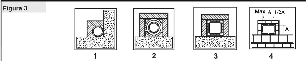
Should the flues have a square or rectangular section, internal edges must be rounded with a radius not lower than 20 mm. For the rectangular section, the maximum ratio between the sides must be = 1.5. A too small section causes a decrease of the draught. It is suggested a minimum height of 4 m.
The following features are FORBIDDEN and therefore they endanger the good operation of the device: asbestos cement, galvanized steel, rough and porous internal surfaces. In Picture 3 gives some examples of execution.
For a correct installation please respect the sections/lengths of the flue shown in the technical data table. B y installations with different dimensions the flue must be suitably sized in accordance with EN 13384-1. The draught created by the flue must be sufficient, but not excessive. A too big flue section can feature a too big volume to be heated and consequently cause difficulties in the operation of the device; to avoid this, tube the flue along its whole height. A too small section causes a decrease of the draught.
ATTENTION : as far as concern the realization of the flue connection and flammable materials please follow the requirements provided by UNI 10683 standard. The flue must be properly spaced from any flammable materials or fuels through a proper insulation or an air cavity.
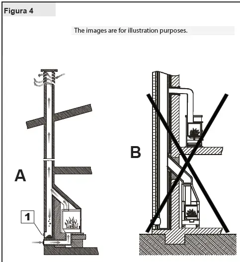
It is FORBIDDEN to let plant piping or air feeding channels pass in the same flue. Moreover, it is forbidden to create movable or fixed openings on the same for the connection of further other devices (Picture 4).
CHIMNEY CAP
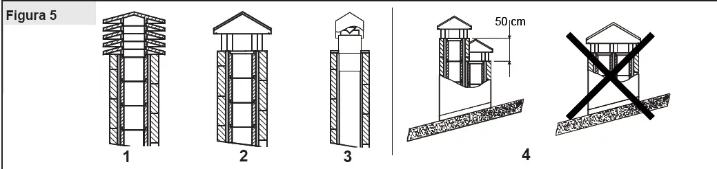
The draught of the flue depends also on the suitability of the chimney cap. Therefore, if it is handicraft constructed, the output section must be more than twice as big as the internal section of the flue (Picture 5).
Should it be necessary to exceed the ridge of the roof, the chimney cap must assure the discharge also in case of windy weather (Picture 6).
The chimney cap must meet the following requirements:
- have internal section equivalent to that of the stack.
- have a useful output section twice as big as the flue internal one.
- be manufactured in such a way as to prevent the penetration of rain, snow, and any other foreign body in the flue.
- be easily checkable, for any possible maintenance and cleaning operation
CONNECTION TO THE FLUE
- The connection to the stack must be performed with stiff pipes in steel comply with all current Standards and
- Regulations and to those envisioned by the Law.
- It is f orbidden to use metallic pipes or pipes in asbestos cement since they jeopardize the safety of the f itting itself, considering that they are subject to tears or breaks resulting in leaks of smoke.
- The exhaust pipe must be air-tight fastened to the stack and can have a maximum inclination of 45°; this to avoid excessive deposits of condensate produced in the initial start-up phases and/or the excessive gripping of soot and moreover it avoids the slowing down of the smokes at output.
- The failed tightness of the connection can cause the malfunction of the device.
- The internal diameter of the connection pipe must be equal to the external diameter of the smokes stub pipe of the device. This is assured by the pipes complying with DIN 1298.
- The chimney pressure (DRAUGHT ) must be at least (see chap. TECHNICAL DATA SHEET) . The measurement has always to be carried out with hot device (rated thermal performance).
- When the depression exceeds 17 Pa (=1.7 mm of column of water), it is necessary to reduce the same by installing an additional draught regulator (butterfly valve).
- IMPORTANT : When using metallic pipes, they must be insulated with proper materials (coatings in insulating fibers resistant up to 600°C ) in order to avoid deterioration of walls or of the counter-hood.
- Before positioning the insert in the pre-existing fireplace, it is necessary to close the upper internal part of the stack using (properly pre-drilled) sheet metal or any other kind of fire-resistant material that can support very high temperatures without suffering any damage. (see Picture 7 pos. 1).
AIR FOR COMBUSTION
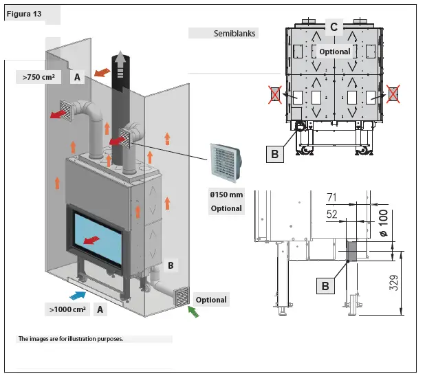
It is necessary to ventilate continuously the space included between the upper part, the sides of the device and the deflector of the fire-proofing material of the hood. For this reason, it is necessary to foresee an intake of air from the bottom (intake of fresh air) and a high output (output of hot air).Each of these openings must be free and it should not be possible to obstruct it; moreover, they must have a minimum surface of at least 3 dm2 (example: 30 x 10 cm grating). In this way, the following targets are achieved:
- a greater safety
- an increase of the heat created by air circulation around the device.
- a better working of the appliance
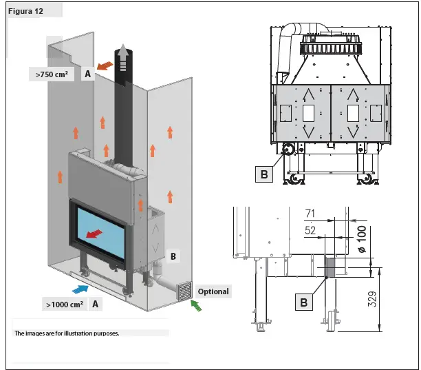
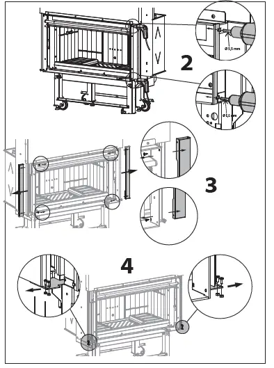
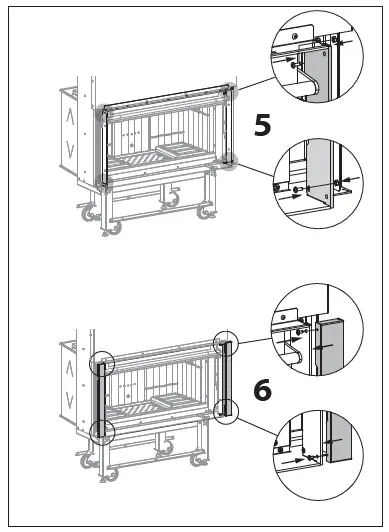
The heat vent grating (Picture 7 pos. 6 – Picture 12 13 14) has to be installed on the upper part of the hood at about 20 cm from the roof. This must always be installed since its function is that of letting the heat collected within the hood (overpressure) flow out into the room.
Ventilation and aeration of the installation premises
AS THE PRODUCT DRAW THEIR COMBUSTION AIR FROM THE PLAC E OF INSTALLATION , IT IS MANDATORY THAT IN THE PLAC E ITS ELF, A SUFFICIENT QUANTITY OF AIR IS INTRODUC ED. IF WINDOWS AND DOORS ARE AIRTIGHT (E.G. BUILT ACCORDING TO ENERGY SAVING CRITERIA), IT IS POSSIBLE THAT THE FRESH AIR INTAK E IS NO LONG ER GUARANT EED AND THIS JEOPARDIS ES THE DRAUGHT OF THE APPLIANCE AND YOUR HEALTH AND SAFETY .
IMPORTANT : For a better comfort and corresponding oxygenation of environment, the combustion air can be directly withdrawn at the outside through a junction which is to be connected with a flexible pipe. The connection pipe (not furnished) must be flat with a minimum diameter of Picture 12 13 14, a maximum length of 4 m and with no more than 3 bends. If there is a direct connection with the outside it must be endowed with a special windbreak.
THERE MANDATORY BE SUFFICIENT QUANTITY OF AIR FOR COMBUSTION AND RE-OXYG ENATION OF THE ROOM TO ENSURE THE DEVICE WILL WORK PROP ERLY . There should therefore be vents letting air in from outside the building and enabling circulation of air for combustion even when the doors and windows are closed.
The air inlets must meet the following requirements:
- THEY MUST BE PROT ECT ED WITH GRIDS, METAL MESH, ETC ., BUT WITHOUT REDUCING THE NET USEFUL SECTION ;
- THEY MUST BE MAD E SO AS TO MAK E THE MAINT ENANCE OPERATIONS POSSIBLE;
- POSITIONED SO THAT THEY CANNOT BE OBSTRUCT ED;
- ANY EXTRACTOR HOODS IN THE ROOM WHERE THE DEVICE IS INSTALL ED MUST NOT OPERAT E AT THE SAM E TIME as this could cause smoke to enter the room, even with the fireplace’s door closed.
| appliance categories | reference standard | percentage of the net opening section with respect to the appliance fumes outlet section | minimum net opening value of the ventilation duct |
| fireplaces | uni En 13229 | 50% | 200 cm² |
| stoves | uni En 13240 | 50% | 100 cm² |
| cookers | uni En 12815 | 50% | 100 cm² |
VENTILATION HOOD OR ADJACENT LOCAL
- WITHOUT outer upper cover OPTIONAL – see Picture 12;
- WITH outer upper cover OPTIONAL – see Picture 13;
- Perform the drilling on the walls or on the existing hood to allow the passage and the application of the (fire-resistant) hoses with a 15 cm diameter equipped with related openings.
- Fasten the pipes by means of clamps to the related collars and openings, after having removed the semi-blanks caps.
- Each pipe must not exceed 2 m of length for natural ventilation and 4 m for forced ventilation, and has to be insulated with insulating materials to avoid noise and dispersion of heat.
- The openings have to be positioned at a height not lower than 2 m from the floor to avoid that hot air at output meets people. Please respect the distance of the convection openings according to the local construction norms;
- The lengths of the canalization pipes must have the same length to avoid the distribution of differing quantities of air from each output.
ALLOWED / NOT ALLOWED FUELS
| Variety | kg/m3 | kWh/kg moistness 20% |
| Beech | 750 | 4,0 |
| Oak | 900 | 4,2 |
| Elm | 640 | 4,1 |
| Poplar | 470 | 4,1 |
| Larch* | 660 | 4,4 |
| Spruce* | 450 | 4,5 |
| Scots pine * | 550 | 4,4 |
LIGHTING
- the construction materials of the involved products are not homogeneous, in fact there are simultaneously parts in cast iron, steel, refractory material and majolica;
- the temperature to which the body of the product is subject is not homogeneous: from area to area, variable temperatures within the
- range of 300°C – 500°C are detected;
- during its life, the product is subject to alternated lighting and extinguishing cycles in the same day, as well as to cycles of intense use or of absolute standstill when season changes;
- the new appliance, before being considered seasoned has to be subject to many start cycles to allow all materials and paints to complete the various elastic stresses;
- in detail, initially it is possible to remark the emission of smells typical of metals subject to great thermal stress, as well as of wet paint.
- Make sure that a strong air change is assured in the room where the appliance is installed.
- During the first starts, do not load excessively the combustion chamber (about half the quantity indicated in the instructions manual) and keep the product continuously ON for at least 6-10 hours with the registers less open than the value indicated in the instructions manual.
- Repeat this operation for at least 4-5 or more times, according to your possibilities.
- Then load more and more fuel (following in any case the provisions contained in the installation booklet concerning maximum load) and, if possible, keep the lighting periods long avoiding, at least in this initial phase, short ON/OFF cycles.
- During the first starts, no object should be leaned on the appliance and in detail on enameled surfaces. Enameled surfaces must not be touched during heating.
- Once the «break-in» has been completed, it is possible to use the product as the motor of a car, avoiding abrupt heating with excessive loads.
- do not add further wood between one complete load and the next;
- do not suffocate the fire by closing the air intakes;
- regular cleaning by a chimney sweep reduces fine particle emissions.
- These instructions are backed by ENERGIA Legno SVIZZERA www.energia-legno.ch
NORMAL OPERATION
THE WA RRANTY DOES NOT COVER THE DAMA GES DUE TO OVERHEATING OF THE EQUIPMENT. You should always use the appliance with the door closed in order to avoid damages due to overheating (forge effect). The adjustment of the registers necessary to reach the rated calorific yield with a depression at the stack of Pascal (see chap. TECHNICAL DATA SHEET) is the following one: see chap.
The appliance works as an intermittent operating appliance. Besides the adjustment of the air for the combustion , the intensity of the combustion and consequently the thermal performance of the device is influenced by the stack. A good draught of the stack requires a stricter adjustment of air for combustion , while a poor draught requires a more precise adjustment of air for combustion . To verify the good combustion, check whether the smoke coming out from the stack is transparent. If it is white, it means that the device is not properly adjusted or the wood is too wet; if instead the smoke is gray or black, it signals that the combustion is not complete (it is necessary a greater quantity of secondary air).
During transition periods when the external temperatures are higher, if there is a sudden increase of temperature it can happen that the combustion gases inside the flue cannot be completely sucked up. The exhaust gases do not come out completely (intense smell of gas). In this case, shake the grating more frequently and increase the air for the combustion. Then, load a reduced quantity of fuel in order to permit a rapid burning (growing up of the flames) and the stabilization of the draught. Then, check that all openings for the cleaning and the connections to the stack are air-tight. In case of doubt , do not operate the product .
MAINTENANCE AND CARE
- Make sure that the power cord is unplugged (if present).
- that the generator is cold all over.
- the ashes are completely cold.
- ensure efficient air exchange in the rooms during the product cleaning operations.
- poor cleaning will compromise correct operation and safety!
PERIODIC CLEANING UNDER USER’S RESPONSIBILITY
The periodic cleaning operations, as indicated in this use and maintenance manual, must be performed with the utmost care after reading the instructions, procedures and frequency described in this use and maintenance manual.
CHECK THE EXTERNAL AIR INTAKE, BY CLEANING IT, AT LEAST ONCE A YEAR. THE STACK MUST BE REGULARLY SWEPT BY THE CHIMNEY SWEEPER.
LET YOUR CHIMNEY SWEEPER IN CHARGE OF YOUR AREA CHECK THE REGULAR INSTALLATION OF THE DEVICE, THE CONNECTION TO THE STACK AND THE AERATION.
IMPORTANT: THE MAINTENANCE AND CARE MUST BE CARRIED OUT ONLY AND EXCLUSIVELY WITH COLD DEVICE . You should only use spare parts approved and supplied by La NORDICA S.p.A. .
Please contact your specialized retailer if you require spare parts. YOU MUST NOT MAKE ANY CHANGES TO THE DEVICE!!!
GLASS CLEANING
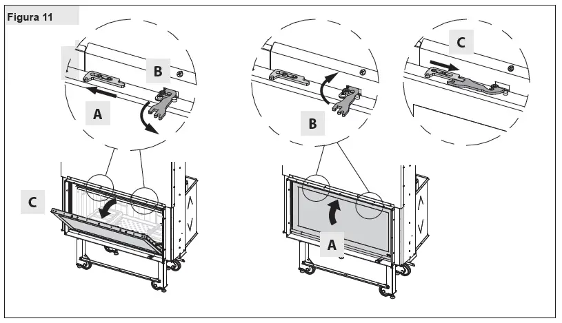
After having checked that the door is completely shut (lowered), unlock the upper latch (Picture 11 pos. A), open the flap and clean the glass, then close the flap and lock the latch before lifting again the door.
Thanks to a specific inlet of secondary air, the accumulation of dirty sediments on the glass-door is reduced with efficacy. Nevertheless this can never be avoided by using solid fuels ( particularly wet wood ) and it has not to be understood as a defect of the appliance.
IMPORTANT: THE CLEANING OF THE SIGHT GLASS MUST BE TO AVOID THE EXPLOSION OF THE SAME.
For the cleaning, it is possible to use specific products or a wet newspaper paper ball passed in the ash to rub it.
DO NOT USE CLOTHS, ABRASIVE OR CHEMICALLY AGGRESSIVE PRODUCTS BY CLEANING THE HEARTH GLASS.
The correct lighting phase, the use of proper quantities and types of fuels, the correct position of the secondary air regulator, enough draught of the chimney-flue and the presence of combustion air are the essential elements for the optimal functioning of the appliance and for the cleaning of the glass
BREAK OF GLASSES: Given that the glass-ceramic glasses resist up to a heat shock of 750°C, they are not subject to thermal shocks. THEIR BREAK CAN BE CAUSED ONLY BY MECHANIC SHOCKS (bumps or violent closure of the door, etc.). THEREFORE, THEIR REPLACEMENT IS NOT INCLUDED IN THE WARRANTY.
CLEANING OUT THE ASHES
All the devices are equipped with a hearth grating and an ash drawer for the collection of the ashes.
It is suggested to empty periodically the ash drawer and to avoid it fills completely in order not to overheat the grating. Moreover, it is suggested to leave always 3-4 cm of ash in the hearth.
CAUTION: The ashes removed from the hearth have to be stored in a container made of fire-resistant material equipped with an air-tight cover. The container has to be placed on a fire-resistant floor, far from flammable materials up to the switching off and complete cooling.
CLEANING THE FLUE
The correct lighting phase, the use of proper quantities and types of fuels, the correct position of the secondary air regulator, enough draught of the chimney-flue and the presence of combustion air are the essential elements for the optimal functioning of the appliance. The device should be completely cleaned at least once a year or ever y time it is a needed (in case of bad working and low yield). An excessive deposit of soot can cause problems in the discharge of smokes and fire in the flue. The cleaning must be carried out exclusively with cold equipment. This operation should be carried out by a chimney sweeper who can simultaneously perform an audit of the flue (checking of possible deposits).
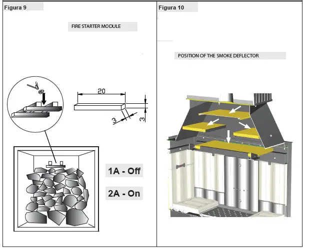
During the cleaning, it is necessary to remove the ash drawer, the grating, and the smoke deflectors from the device in order to ease the fall of the soot. The deflectors can be easily extracted from their seats since they are not fastened using screws. Once the clearing has been carried out, place them back in their seats (Picture 10).
CAUTION: The lack of the deflectors ca uses a strong depression, with a too fast combustion, an excessive consumption of wood with related overheating of the device .
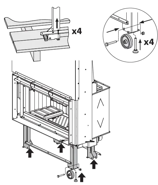
MAINTENANCE OF THE EXTENSIBLE GUIDES
To work silently, as well as in a reliable and robust way, the doors are fastened to the extensible ball guides. By using the device continuously, the lubricant of the guides tends to run out progressively in time making their sliding more difficult and noisy. For this reason, together with each device a high temperature grease is supplied in order to make the lubrication of the guides possible for the user, in case it becomes necessary (excessive noise or reduction of smoothness).
After having completely lifted the door of the stack, using a syringe, apply internally on the track on a visible point, as high as possible, two grease balls (corresponding to 0.5 ml of the graduated scale of the syringe). Pay attention not to exceed the suggested quantity. Repeat the same operation on the other track and lift and lower the door many times so that the grease distributes on all balls.
CAUTION : use exclusively the grease supplied by La NORDICA S.p.A.
SUMMER STOP
After cleaning the hearth, chimney and hood, totally eliminating the ash and other eventual residues, close all the doors of the hearth and the relevant registers; in case you disconnect the appliance from the chimney you must close its openings in order to let work others possible appliances connected to the same flue.
We suggest performing the cleaning operation of the flue at least once per year; verifying in the meantime the actual status of the rope seals, which cannot ensure the good operation of the equipment if they are not in good condition and are not making a good seal! In this case the seals must be replaced.
In presence of dampness in the room where the product has been placed, we advise you to put absorbent salts into the hearth.
If you want to keep for long the aesthetic look of the cooker it is important to protect its internal walls
in row cast iron with neutral Vaseline
Routine maintenance performed by qualified technicians
Routine maintenance must be performed at least once a year.
Using wood as solid fuel, the generator requires annual routine maintenance, which must be performed by a qualified technician, using only original spare parts.
Failure to comply can jeopardies the safety of the appliance and make the warranty null and void.
Respecting the frequencies of cleaning reserved for the user described in the use and maintenance manual, the generator is guaranteed correct combustion over time, preventing any anomalies and/or malfunctioning that could require more interventions of the technician.
Requests for routine maintenance are not contemplated in the product warranty.
GASKETS
The gaskets guarantee the tightness of the product and its consequent good functioning.
They must be controlled periodically. They must be replaced immediately if they are worn or damaged.
These operations must be carried out by a qualified technician.
Connection to the flue
Vacuum and clean the pipe that leads to the flue yearly or any time that it is necessary. If there are horizontal tracts, the residue must be removed before it can prevent the passage of the fumes.
CALCULATION OF THE THERMAL POW ER
There is not an absolute rule for calculating the correct necessary power. This power is given according to the space to be heated, but it depends also largely on the insulation. On an average, the calorific value necessary for a properly insulated room is 30 kcal/h per m3 (for an external temperature of 0°C).
Given that 1 kW corresponds to 860 kcal/h, it is possible to adopt a value of 35 W/m3. Let’s suppose one wishes to heat a room of 150 m3 (10 x 6 x 2.5 m) in an insulated apartment. In this case, it is necessary to have 150 m3 x 35 W/m3 = 5250 W or 5,25 kW. As main heating, a 8 kW device is therefore sufficient.
| Approximate combustion value | Required quantity in relation to 1 kg of dry wood | |||
| fuel | unit | kcal/h | kw | |
| Dry wood (15% humidity) | kg | 3600 | 4.2 | 1,00 |
| wet wood (50% humidity) | kg | 1850 | 2.2 | 1,95 |
| wood briquettes | kg | 4000 | 5.0 | 0,84 |
| brown coal briquettes | kg | 4800 | 5.6 | 0,75 |
| normal anthracite | kg | 7700 | 8.9 | 0,47 |
| coke | kg | 6780 | 7.9 | 0,53 |
| natural gas | m3 | 7800 | 9.1 | 0,46 |
| naphtha | l | 8500 | 9.9 | 0,42 |
| electricity | kwh | 860 | 1.0 | 4,19 |
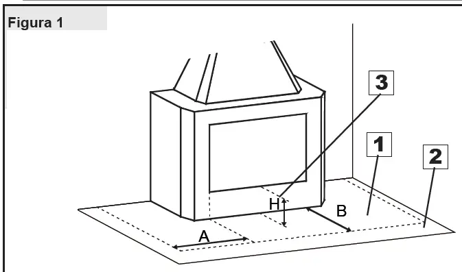
- A = H+20 cm = > 40 cm
Side limit of the protected area - B = H+30 cm = > 60 cm
Front limit of the protected area
- Protection of the floor with incombustible material
- Flooring in combustible material
- Height of the hearth surface from the ground
ACCORDING TO THE REGIONAL REGULATIONS –
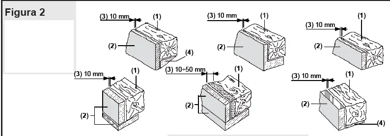
- Beam
- Refractory insulating
- Air pocket
- Metallic protection
ACCORDING TO THE REGIONAL REGULATIONS
- Steel flue with double chamber insulated with material resistant to 400°C. Efficiency 100% excellent.
- Refractory flue with double insulated chamber and external coating in lightweight concrete. Efficiency 100% excellent.
- Traditional clay flue square section with cavities. Efficiency 80% good.
- Avoid flues with rectangular internal section whose ratio differs from the drawing. Efficiency 40% poor.
- Material comply with all current Standards and Regulations and to those envisioned by the Law.
- Representation of a correct flue with air-tight door for the collection and discharge of solid unburnt materials.
- The connection of more than one device to the flue is not recommended. Each device must have its own flue.
- Door for cleaning
- Industrial chimney cap with pre-fabricated elements – it allows an excellent discharge of the smokes.
- Handicraft chimney cap. The right output section must be at least twice as big as the internal section of the flue (ideal value: 2.5 times).
- Chimney cap for steel flue with internal cone deflector of smokes.
- In case of flues side by side, a chimney cap must be higher than the other one of at least 50 cm in order to avoid pressure transfers between the flues themselves.

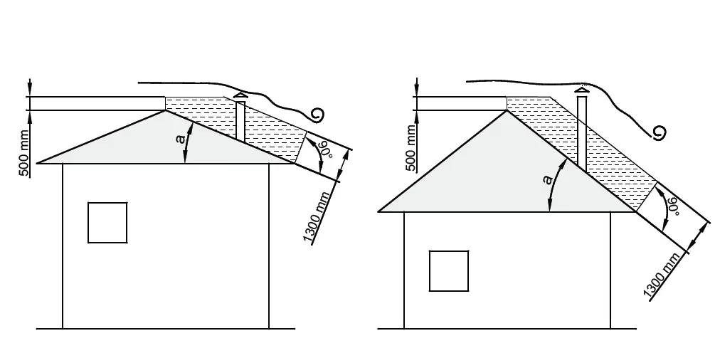
- The chimney cap must not show hindrances within 10 m from walls, pitches and trees. Otherwise raise it of at least 1 m over the hindrance. The chimney cap must exceed the ridge of the roof of at least 1 m.
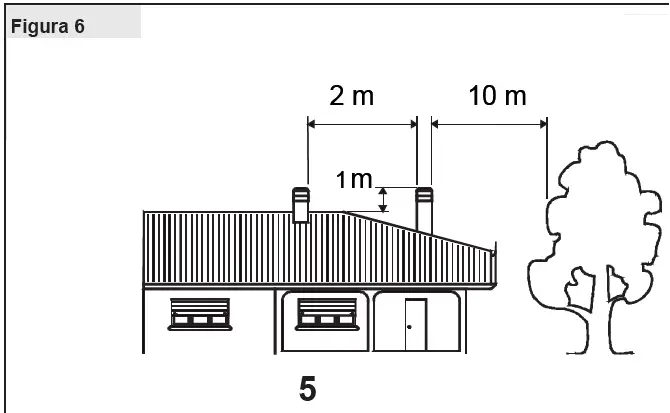
CHIMNEY CAPS – DISTANCES AND POSITIONING UNI 10683
inclination of the roof
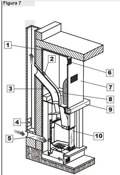
- Insulating material
- Insulating coating with external aluminum sheet
- Door for cleaning
- External air intake
- Heat drain grating
- Fire-retardant counter-hood
- Maximum inclination 45°
- Shield wooden parts with insulating material
All the minimum safety distances (cm) are shown on the product data plate and lower values must not be used (See DECLARATION OF PERFORMANCE)
ACCORDING TO THE REGIONAL REGULATIONS
The images are for illustration purposes.
Safety distance from combustible materials.
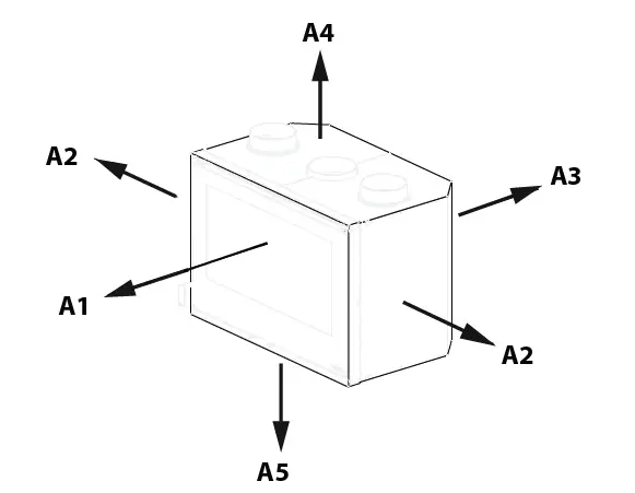
The images are for illustration purposes.
| cm | A1 | A2 | A3 | A4 | A5 |
| MONOBLOCCO 1000 EVO | 150 | 50 | 10 | – | – |
All the minimum safety distances (cm) are shown on the product data plate and lower values must not be used (See DECLARATION OF PERFORMANCE).
ATTENTION: We recommend making the counter plate in fire-retardant plasterboard with self-supporting metal frame, so that its weight does not bear on the aesthetic covering (marble).
- A. Natural convection
- B. External air intake for the stack
- C.Forced convection
ATTENTION: We recommend making the counter plate in fire-retardant plasterboard with self-supporting metal frame, so that its weight does not bear on the aesthetic covering (marble).
- A. Natural convection
- B. External air intake for the stack
- C. Forced convection
ATTENTION: We recommend making the counter plate in fire-retardant plasterboard with self-supporting metal frame, so that its weight does not bear on the aesthetic covering (marble).
- A. Natural convection
- B. External air intake for the stack
- C. Forced convection
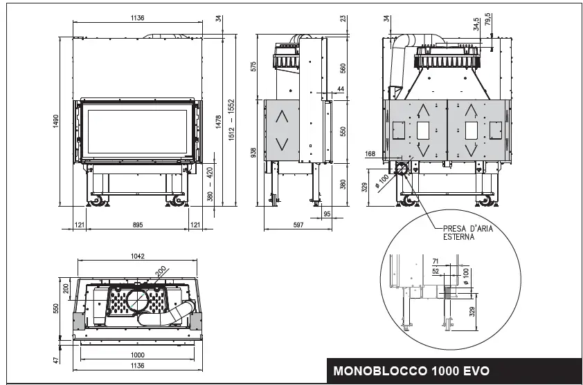
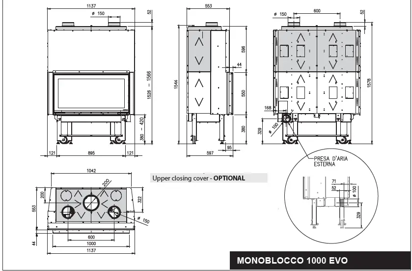
TECHNICAL DATA sheet.
| MONOBLOCCO 1000 EVO | |||||||||
| Normative documents | EN 13229 | ||||||||
| Rated thermal power (kW) | 12,3 | ||||||||
| m3 heatable (30 kcal/h x m3) | 352 | ||||||||
| hourly consumption (kg/h) | 3,4 | ||||||||
| yield (%) | 85,6 | ||||||||
| Ventilation (adjustable) | NO | ||||||||
| Ventilation KIT OPTIONAL Kit Gebläse EXTRA | SI yES JA OUI SIM | ||||||||
| Depression at the stack in Pa (mmh2O) | 10 (1,0) | ||||||||
| Smoke output Ø | 20 | ||||||||
| height ≥ (m) ; | ≥ 4 (*) 25×25÷Ø25 ≥ 6 (*) 20×20÷Ø20 | ||||||||
| Exhaust gas emission in g/s | 9,5 | ||||||||
| Exhaust gas temperature in °C | 215 | ||||||||
| MONOBLOCCO 1000 EVO | |||||||||
| Aria PRIMARIA regolabile | SI | ||||||||
| Adjustable PRIMARy air | yES | ||||||||
| Einstellbare PRIMÄRLUFT | JA | ||||||||
| Air primaire RéGLABLE | OUI | ||||||||
| Aire PRIMARIO regulable | SIM | ||||||||
| Aria sECONDARIA regolabile | SI | ||||||||
| Adjustable SECONDARy air | yES | ||||||||
| Einstellbare SEKUNDÄRLUFT | JA | ||||||||
| Air SECONDAIRE réglable | OUI | ||||||||
| Aire SECUNDARIO regulable | SIM | ||||||||
| Aria TERZIARIA regolabile | PRETARATA | ||||||||
| Adjustable TERTIARy Air | PRE-ADJUSTED | ||||||||
| Einstellbare TERTIÄRLUFT | AUSGESTATTET | ||||||||
| Air TERTIAIRE réglable | PRéDéTERMINé | ||||||||
| Aire terciario regulable | PRECALIBRADA | ||||||||
| Certification | EN 15a B-VG 2° BImSchV | ||||||||
| Approximate weight (kg) | 292 | ||||||||
| External measures (mm): / | 1136 | ||||||||
| Außenabmessungen (mm): / Mesures externes (mm) : / Medidas | |||||||||
| exteriores (mm): | |||||||||
| L= larghezza / W = width / L= Breite / L = largeur / L= ancho | |||||||||
| H= altezza / h = height / h= höhe / h = hauteur / h= alto | |||||||||
| P= profondità / D =depth / P=Tiefe / P =profondeur / P=profundidad | |||||||||
| hearth opening size in mm (W x h) | 870 x 345 | ||||||||
| hearth size in mm (W x h x D) | 840 x 447 x 340 | ||||||||
| Focolare | Ghisa / NORDIKER Cast-Iron / NORDIKER Gusseisen / NORDIKER | ||||||||
| Feuerraum | |||||||||
| hearth | |||||||||
| Foyer | |||||||||
| Fogón | |||||||||
200 mm diameter can be used with flue of no less than 6 m. The proposed value are indicative. The installation must, in any case, be sized and verified according to the general calculation method in UNI EN13384-1 or by another method of proven efficiency.
DIMENSIONS SHEETS
BEFORE THE INSTALLATION PERFORM THE FOLLOWING CHECKS.
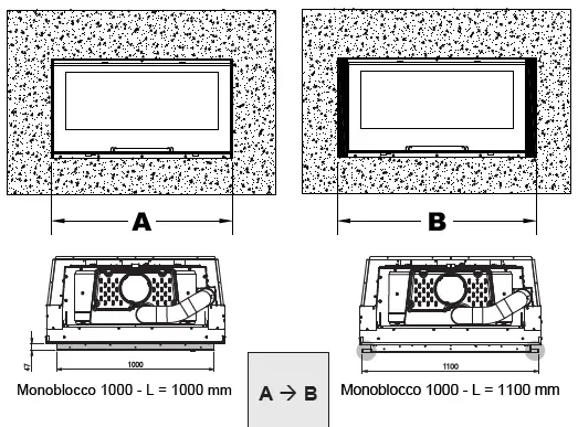
| MONOBLOCCO 1000 EVO | ||
| A | 1000 mm | |
| B | 1100 mm |


![Pleasant Hearth Electric Fireplace User Manual [model: 24-900-002]](https://static-data1.manualsee.com/1/img/253/68707/2021/02/Pleasant-Hearth-electric-fireplace-User-Manual-Model-24-900-002.jpg "Pleasant Hearth Electric Fireplace User Manual [model: 24-900-002]")


![Pleasant Hearth Electric Fireplace Insert User Manual [model: 24-900-002]](https://static-data1.manualsee.com/1/img/92/71366/2021/02/Pleasant-Hearth-Electric-Fireplace-Insert-User-Manual-Model-24-900-002.jpg "Pleasant Hearth Electric Fireplace Insert User Manual [model: 24-900-002]")


