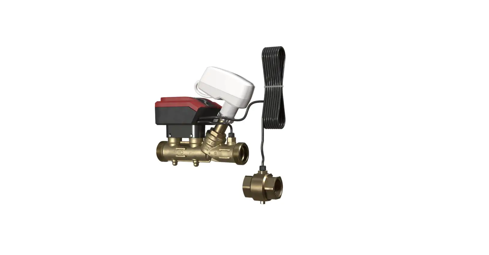
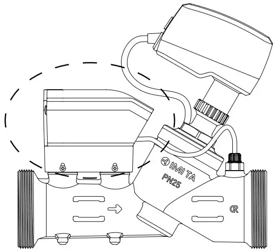
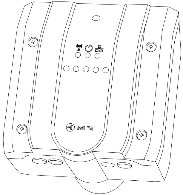
IMI Hydronic Engineering DN 65-125 TA-Smart 2-Way Control Valve Instruction Manual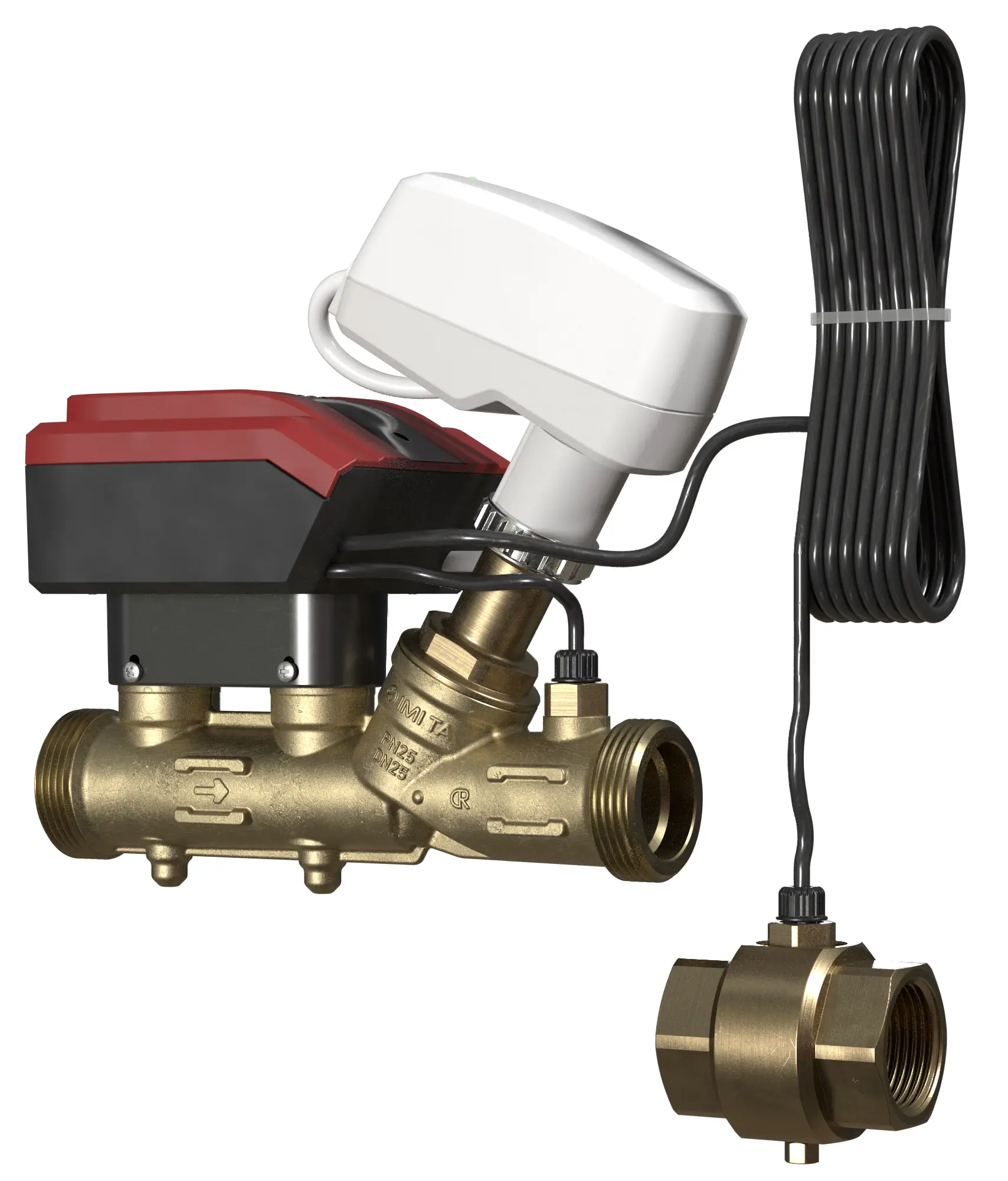
 Intendend use: For measuring and control in heating and cooling systems.
- The water quality requirements described in VDI2035 should be respected
- TA-Smart can be cleansed with a damped cloth and a lenient cleaning agent.
- Insulated wires and cables shall retard flame propagation with a flammability RATING of UL 2556 VW-1 or equivalent.
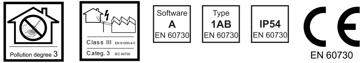
24 VAC/VDC operating only with safety isolating transformer according EN 61558-2-6.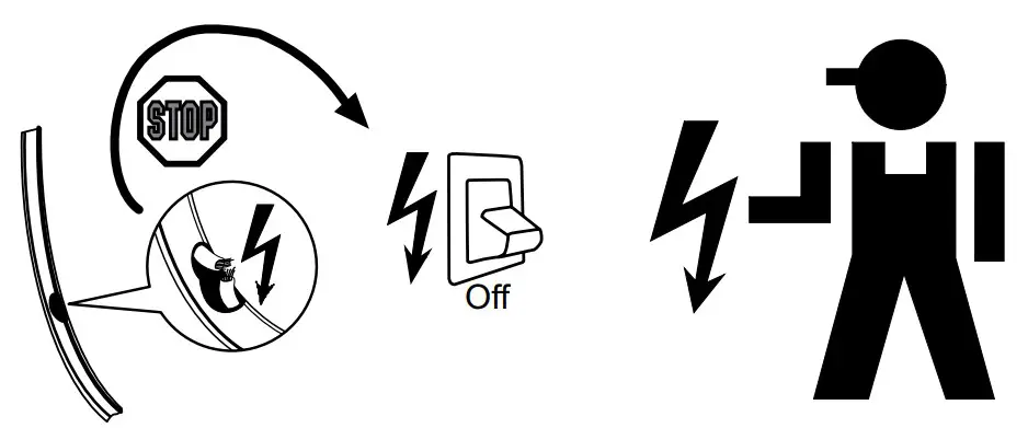
Service/Repair
IMI Hydronic Engineering
If the TA-Smart is used in any other application than specified by IMI Hydronic Engineering the protection provided by the equipment may be impaired.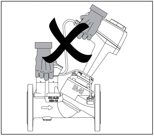
We reserve the right to introduce technical alterations without prior notice
Technical specifiactions valid at an altitude of max. 2000 m
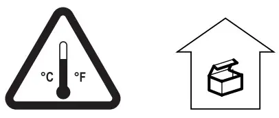 -20°C – +70°C (-4°F – +158°F) (5-95%RH, non-condensing
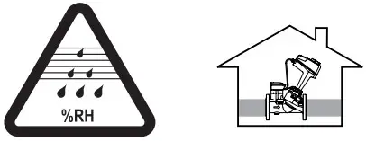 0°C – +50°C (32°F – +122°F) (5-95%RH, non-condensing
 Input signal
- Output signal
- Control mode
- Flow setting
- Media
- Characteristic
BACnet MS/TP, BACnet IP, Modbus RTU, Modbus TCP
Proportional
0(2)-10 VDC 47 kΩ 0(4)-20 mA, 500 Ω
Power supply
24 VAC +6%/-10%, 50/60 Hz ±15% 24 VDC +15%/-10%
Power consumption
- Operating
DN 65-80: < 5.8 W (24 VDC); < 10 VA (24 VAC).
DN 100-125: < 7.7 W (24 VDC); < 10.8 VA (24 VAC) - Standby
![]() EN 61010
EN 61010
 Contains Transmitter Module FCC ID: X8WBC840M
-10°C – +110°C (14°F – +230°F)
Water and water-glycol mixtures (0-57%)
PN 16/25 (Class 150)
| DNPN 16 | D[mm] | L[mm] | H[mm] | |
| 65 | 185 | 4 | 290 | 377 |
| 80 | 200 | 8 | 310 | 380 |
| 100 | 220 | 8 | 350 | 438 |
| 125 | 250 | 8 | 400 | 444 |
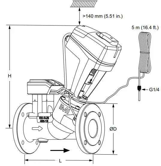
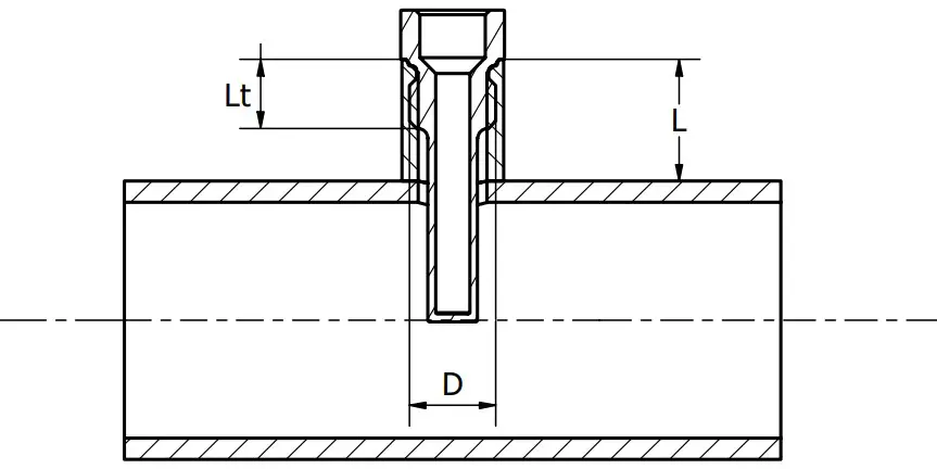
Art. No
DN 65-80 G1/4 322230-00400 L = 30 mm (1.18 in.)
DN 100-125 G3/8 322230-00402 L = 58 mm (2.28 in.)
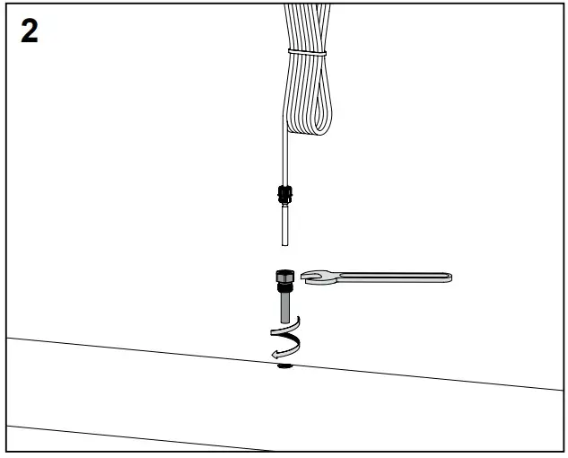
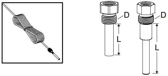
| Pipe | L | Lt | D |
| 65-80 (2 1/2” – 3”) | <15 mm<0.59 in. | <22 mm<0.87 in. | G1/4 |
| 100-125 (4” – 5” | <30 mm<1.18 in. | <22 mm<0.87 in. | G3/8 |
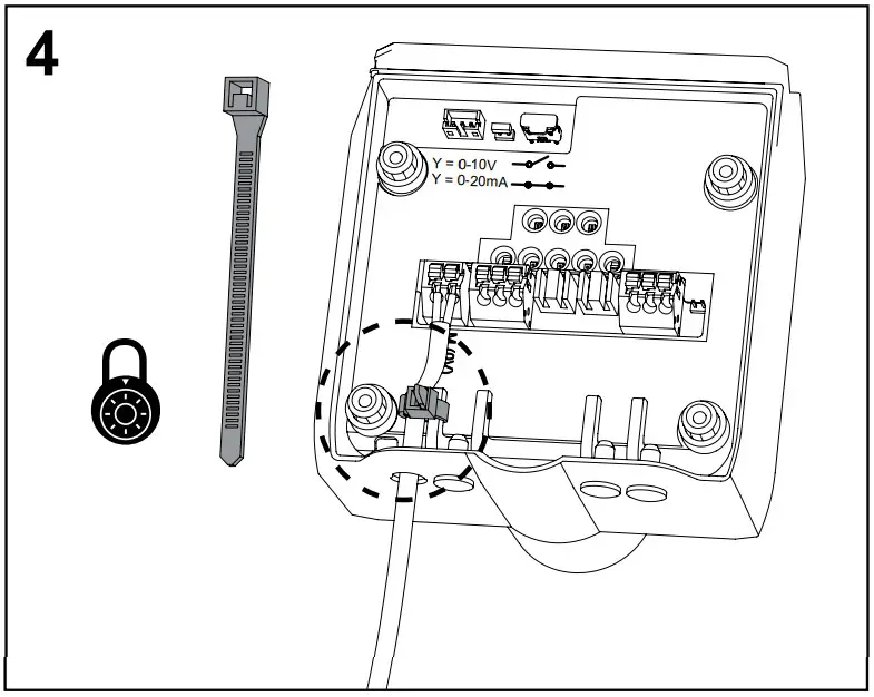
Wiring diagrams
| Terminal | Description |
| L24 | Power supply 24 VAC/VDC. |
| M* | Neutral for power supply 24 VAC/VDC and signals. |
| XV | Output signal 0(2)-10 VDC, max. 8 mA or min. load resistance 1.25 kΩ. |
| M (0V)* | Neutral for signal. |
| Y | Input signal 0(2)-10 VDC, 47 kΩ or 0(4)-20 mA, 500 Ω (selectable by jumper XX). |
| Ethernet | |
| RX – | Ethernet connector wire position 6 |
| RX + | Ethernet connector wire position 3 |
| TX – | Ethernet connector wire position 2 |
| TX + | Ethernet connector wire position 1 |
| RS485 | |
| A | RS485 Data + |
| B | RS485 Data – |
| M (0V)* | Neutral for signal. |
USB Only for IMI use.
Serial Debug Only for IMI use.
All M terminals are internally connected.
Standard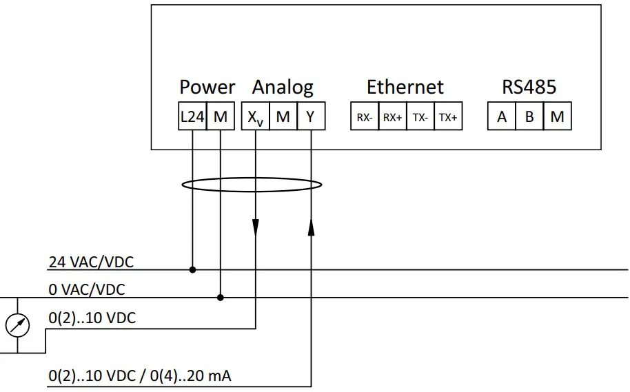
 24 VAC/VDC operating only with safety isolating transformer according EN 61558-2-6
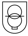
Modbus RTU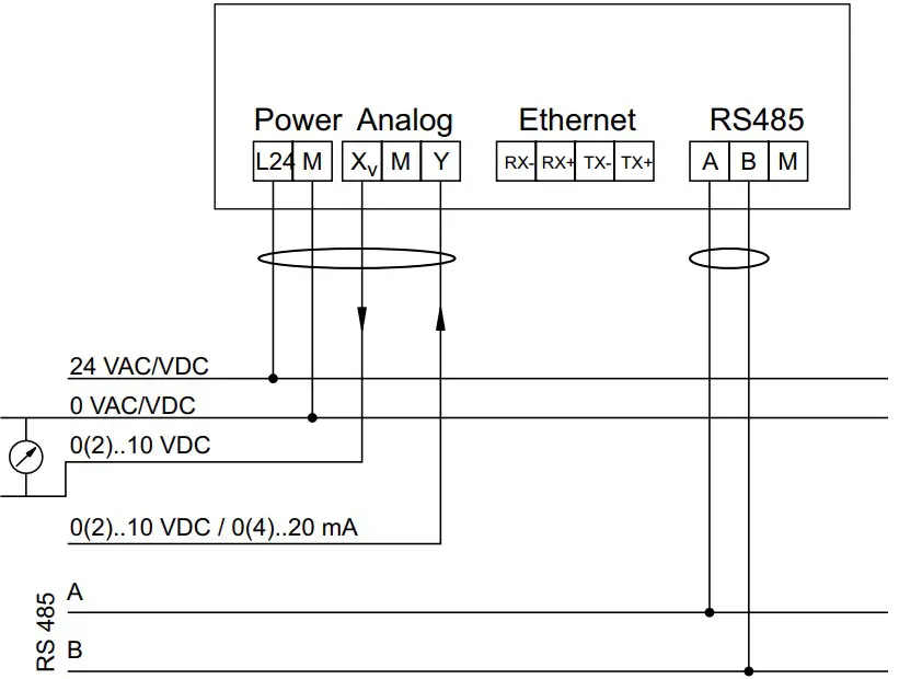
Note:
- A, B and M terminals are NOT isolated from all other terminals.
- GND (M – 0V) is common to power supply, analog signals and RS 485.
- In case of AC power supply, L24 and M should be connected to the same phase for each TA-Smart.
- GND (0V) of RS 485 should be connected to 0 VAC/VDC on the controller side.
- GND (0V) of analog input/output should be connected to 0 VAC/VDC on the controller side.
24 VAC/VDC operating only with safety isolating transformer according EN 61558-2-6
Modbus TCP
Note:
Ethernet cable shall be Cat 5e or Cat 6 cable. Wire colour indication is for T568B pinout.
24 VAC/VDC operating only with safety isolating transformer according EN 61558-2-6.
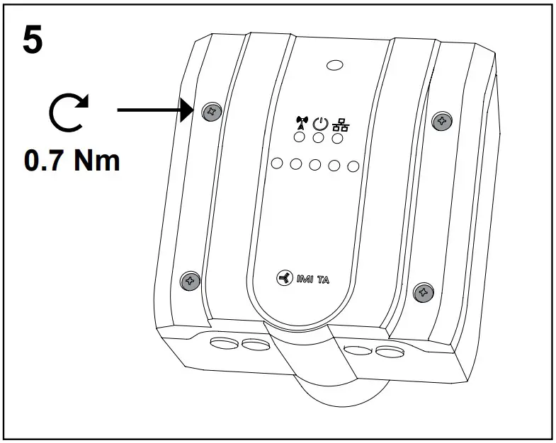
LED
| LED | Colour | Description | |
| Green | – – – – – | Status OK | |
| Green | – – – – – – – – – – | Initiating (start up) | |
| Red | – – – – – | Error (→ HyTune, Cloud, Bus) | |
| Off | No power supply | ||
 | Blue | –––––––––– | Bluetooth active |
| Blue | – – – – – | Bluetooth active (no device connected) | |
| Off | Wireless disactivated (or no power supply) | ||
 | Green | –––––––––– | Ethernet connected |
| Green | – – – – – – – – – – | Data being transferred (Ethernet or RS485, if Ethernet not connected) | |
| Off | Ethernet and RS485 not connected (or no power supply) |
Operation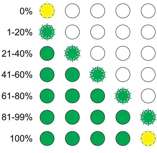
Calibration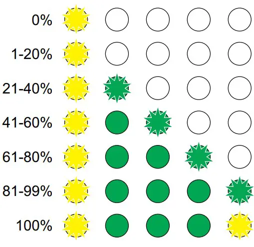
Identification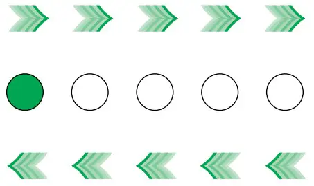
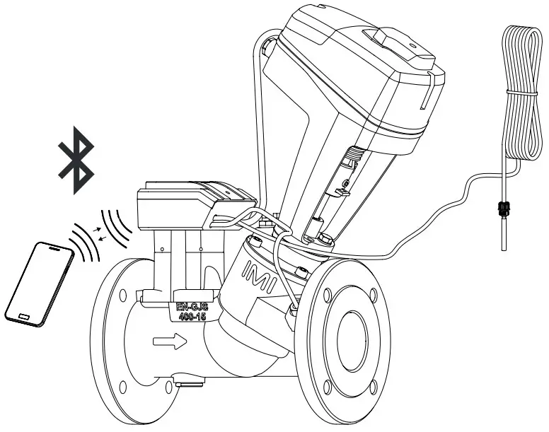
HyTune app
For setting of control parameters use HyTune app.


We reserve the right to introduce technical alterations without prior notice.
IMI Hydronic Engineering AB, 524 80 Ljung, Sweden.
www.imi-hydronic.com