SENNHEISER TeamConnect Ceiling 2 Ceiling Microphone
Planning guide for system integrators
2023-01 | v2.0
Introduction
This document is intended for system integrators and room planners and serves as a planning guide for installing the TeamConnect Ceiling 2 (TCC2) in a room.
This planning guide contains recommendations for the optimal positioning of one or more TCC2 units in various room scenarios.
Sennheiser electronic GmbH & Co. KG provides both 2D and 3D CAD files to enable accu-rate simulation of the coverage area based on the information in this document.
Detailed planning is necessary to ensure that the TCC2 is precisely adapted to the room, even with the default settings. Using the Control Cockpit software, you can then make manual or automatic changes to the system settings while the unit is running in order to finely tune it to the specific room conditions.
This planning guide addresses the following:
- The intended use of the TCC2 device
- Selecting the optimal installation position based on the background noise in the room
- The dimension of the room, based on the floor area
- Basic and alternative options for installing the device in the room
- Installation of the device based on furnishings in the room
- Dealing with potential sources of interference to ensure lossless speech pickup
- The preferred horizontal and vertical alignment of the device to achieve complete three-dimen-sional coverage of the active zones in the room
- How voice quality is directly affected by the horizontal and vertical alignment of the device in the room
Intended use
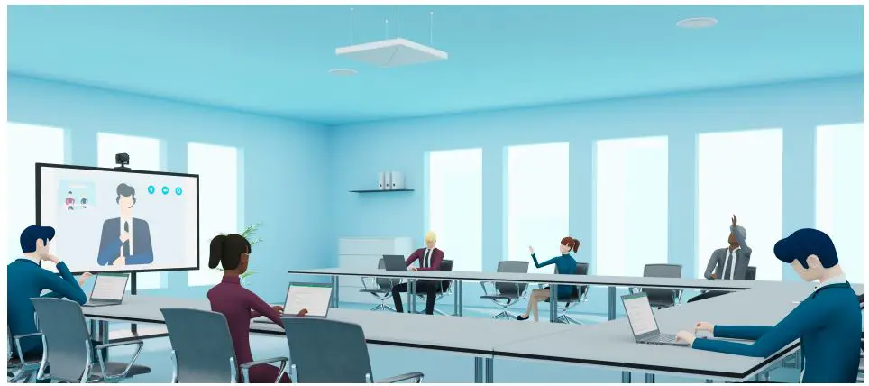
The TCC2 is designed for indoor use and may be used for commercial applications. Typical use cases include closed rooms for holding lectures, conferences, meetings or other events that involve both unidirectional and bidirectional speech. The size of the room determines the number of units required, which you can combine to form a complete system.
The TCC2 is not suitable for use in the music industry or in applications with short or abrupt speech, such as concerts or musicals.
Requirements for the room
Background noise level
To achieve the best possible speech intelligibility, the level of background noise in the room should not exceed 45 dBA.
As measured by the Speech Transmission Index (STI), the TCC2 achieves a value of 0.79 under these conditions, which is classified as “excellent” speech intelligibility. The STI is used for acoustic appli-cations to determine the quality of speech transmission with or without a microphone.
If the reference noise level of 45 dBA is not achieved in a room, you can use the Control Cockpit software to adjust the room acoustics later while the unit is running. The TCC2 offers settings for adjusting the “Sensitivity Threshold” and for suppressing elevated background noise during pauses in speech.
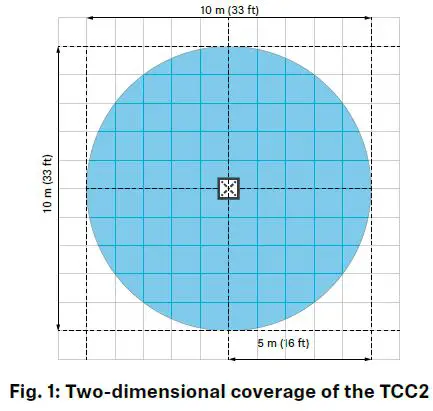
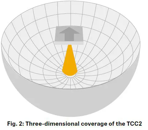
The TCC2’s coverage radius determines the suitable room size. With only one device in a room, the device covers a diameter of 10 m (30 ft) in the shape of a conical hemisphere originating from the installation point (Fig. 1 and Fig. 2). The TCC2 is therefore particularly suitable for rooms of 50 m² (538 ft²) or larger.
To achieve the ideal installation height of between 2.5 m (8 ft) and 3 m (10 ft), the TCC2 can be suspended up to 5 m (16 ft) from the ceiling using the optional suspension kit. Suspending the device from a higher ceiling (> 5 m (16 ft)) requires a customized suspension solution, which is not available as an accessory (for more details, see “Minimum and maximum distances in the room”).
Small room (< 50 m²)
The TCC2 may also be used effectively in smaller rooms (e.g. meeting rooms < 50 m²), depending on the room acoustics, the ambient noise and the presenter’s speaking volume.
Large room (≥ 50 m²)
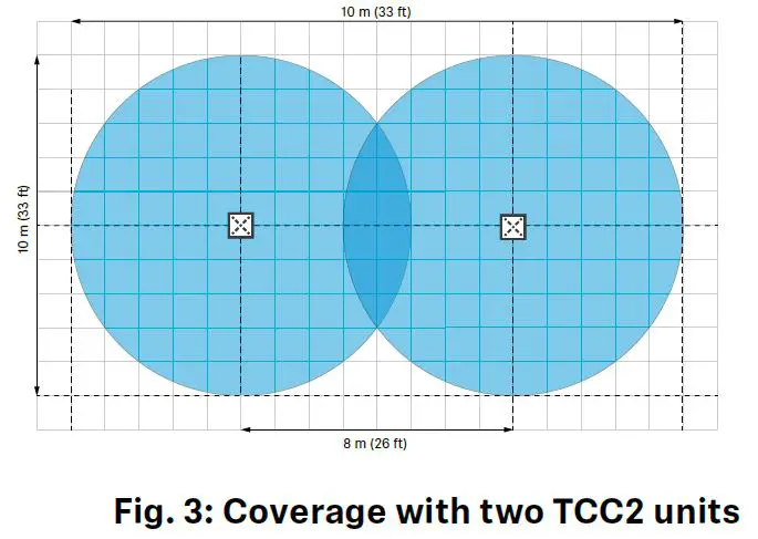
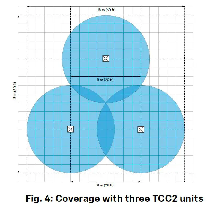
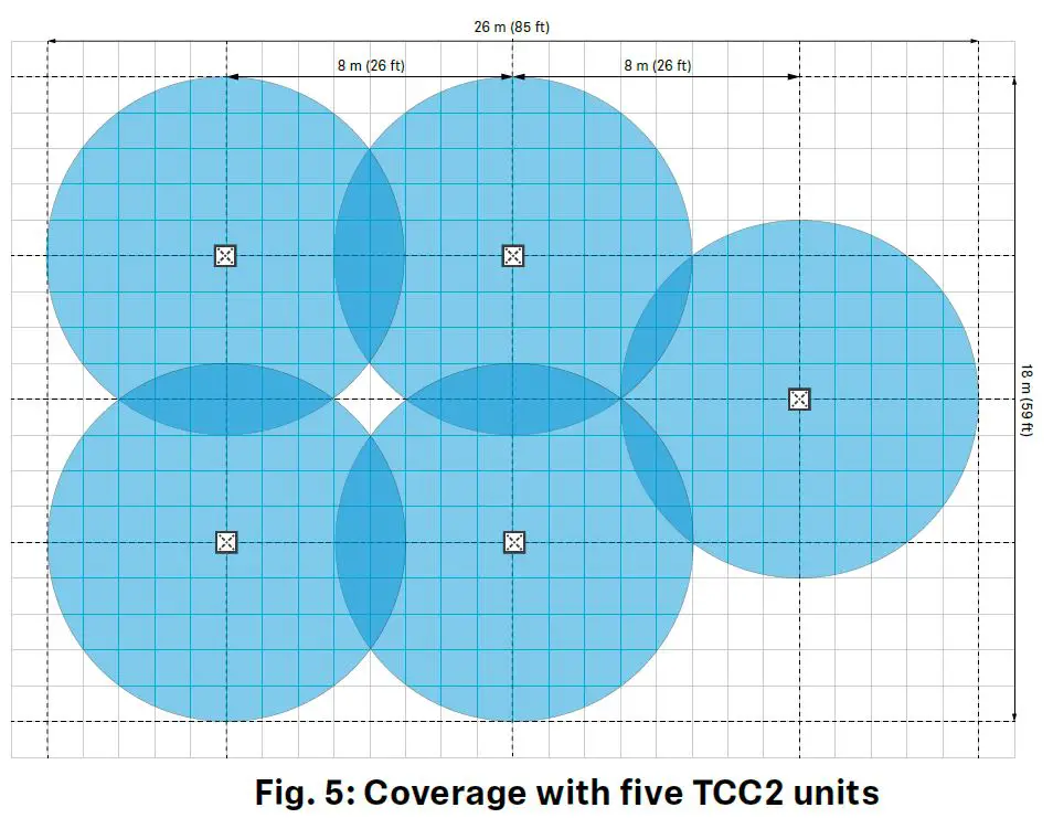
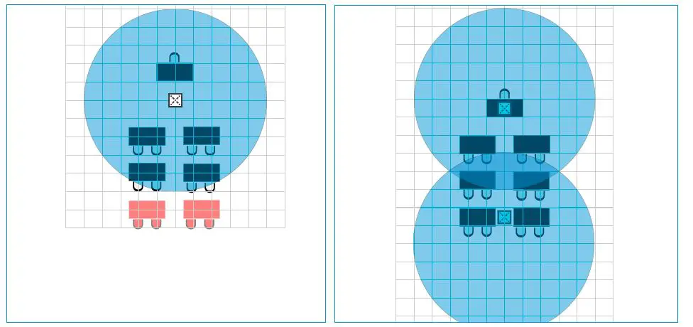
In large rooms, you can extend the coverage as needed by combining multiple TCC2 units into a complete system. When planning, note that the distance between the center of each device should be between 7 and 8 m (23 to 26 ft). This results in an overlap of approx. 1 to 2 m (3 to 7 ft), which ensures continuous coverage (Fig. 3 to Fig. 5).
Recommended room coverage with the TCC2
| Area in m² (ft²) Quantity of TCC2 units | |
| < 50 (538) | 1 |
| ≥ 50 (538) < 100 (1076) | 2 |
| ≥ 100 (1076) < 150 (1615) | 3 |
| ≥ 150 (1615) < 200 (2153) | 4 |
| ≥ 200 (2153) < 250 (2690) | 5 |
| ≥ 250 (2690) < 300 (3229) | 6 |
| ≥ 300 (3229) < 350 (3767) | 7 |
| ≥ 350 (3767) < 400 (4306) | 8 |
| ≥ 400 (4306) < 450 (4844) | 9 |
| ≥ 450 (4844) < 500 (5382) | 10 |
| … | … |
Recommended room heights
Installation options
The TCC2 can be installed in two different ways:
- Installation below the ceiling (four variants)
- Installation in the room (two variants)
For each variant, there are certain minimum and maximum distances that must be observed during installation (see “Minimum and maximum distances in the room”).
When planning, do not position the TCC2 directly next to lights or other electrical devices. When positioning the TeamConnect Ceiling in the ceiling, allow a minimum distance of 0.5 m (1.6 ft) around the unit (see “Positioning in the room”).
Classic installation in or below the ceiling
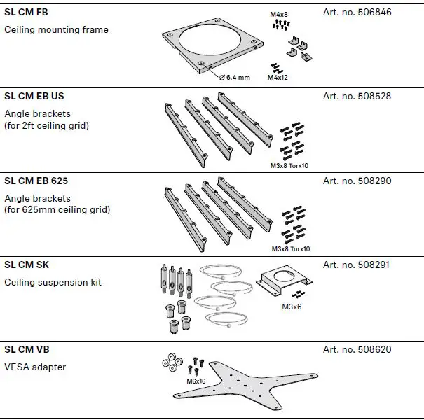
There are four different variants for installing the unit in or below the ceiling, each of which requires additional accessories (see “Accessories”). Dowels and screws that are suitable for the room ceiling are also required for installation.
Variant 1
Installed flush in a dropped/coffered ceiling
The TCC2 can be easily installed in a dropped or coffered ceiling with square ceiling tiles (600 x 600 mm). Angle brackets are available for ceiling tiles with standard dimensions of 2 ft or 625 mm.
• 2 ft grid: SL CM EB US (Art. no. 508528)
• 625 mm grid: SL CM EB 625 (Art. no. 508290)
• Ceiling suspension kit SL CM SK (Art. no. 508291) for optional protection against falling)
For further instructions, see “Mounting in or below the ceiling”.
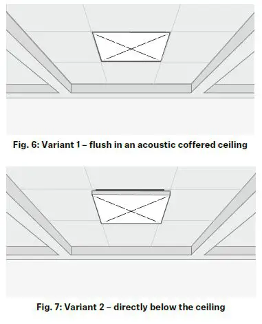
Variant 2
Mounted directly below the ceiling
To mount the unit directly below the ceiling (Fig. 7), you need the SL CM FB (Art. no. 506846) ceiling mounting frame. For further information, see “Mounting in or below the ceiling”.
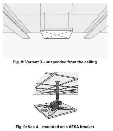
Variant 3
Suspended from the ceiling
For suspended mounting (Fig. 8), you need the SL CM SK (Art. no. 508291) ceiling suspension kit.
For further information, see “Mounting below the ceiling (suspended)”.
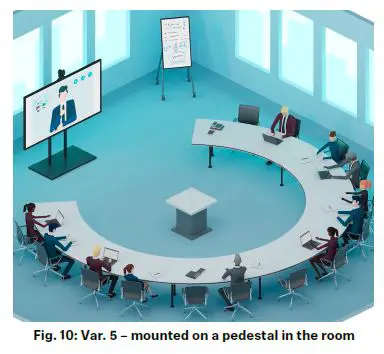
Variant 4
Mounting on a VESA mount
The SL CM VB VESA (Art. no. 508620) adapter (available separately) allows you to mount the TCC2 on any 100 x 100 mm or 200 x 200 mm VESA mount.
Alternative installation in the room
In addition to the classic installation in or below the ceiling, there are two other variants for mounting the TCC2 in the room. Both variants are suitable for rooms that cannot accommodate conventional installations below the ceiling because of their characteristics or furnishings.
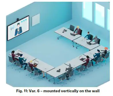
Variant 5
Mounted on a pedestal in the room
In an unconventional room with round tables, decorative walls or ceilings, etc., the TCC2 can be mounted upside down on a pedestal in the middle of the room. With flexible coverage of 180° horizontally and 360° vertically, the TCC2 will reliably capture everyone’s speech within a 4 m (13 ft) radius.
The SL CM FB (Art.no. 506846) ceiling mounting frame should be used to additionally secure the TCC2 against falling from the pedestal or from a fixed elevation. For further information, see “Mounting on a pedestal in the room”.
Variant 6
Mounted vertically on the wall Mounting the TCC2 vertically on a wall is also suitable for rooms where classic installation below the ceiling is not possible.
When mounting vertically, note that there may be greater differences in volume between individual participants, according to their distance from the unit. However, mounting on the wall has no effect on the final acoustic result.
For mounting on the wall, the SL CM FB (Art.no. 506846) ceiling mounting frame is required. For further information, see “Mounting on the wall”.
Please note that with this installation plan, there should be no presenters directly in front of or with their backs to the TCC2. The distance between the TCC2 and the nearest presenter should be at least 1 m (3 ft).
Minimum and maximum distances in the room
Each TCC2 mounting variant has different requirements regarding sound distribution and reflections in the room. To ensure that speech is picked up with as little loss as possible, certain distances should be maintained from reflective surfaces such as walls, ceilings and equipment, as well as from presenters.
A microphone that is suspended too low or too high may result in a loss of level and clarity in detected speech, as participants may be outside the actual coverage radius (see “Sound distribution”).
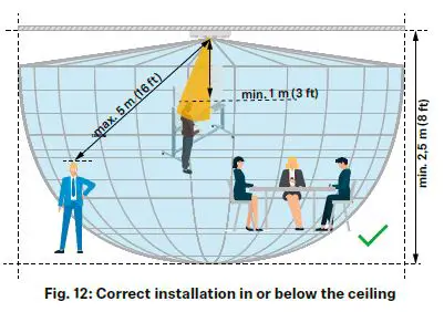
Regardless of the type of installation, we recommend adhering to the following distances during planning:
- The distance between the farthest presenter and the TCC2 is max. 5 m (16 ft).
- The distance between the closest standing presenter and the TCC2 is min. 1 m (3 ft).
- The distance between the TCC2 and other devices on the same installation surface (e.g. lights, built-in air conditioners, projectors, etc.) is at least 0.5 m (see “Positioning in the room”).
Individual recommendations
Mounting in or below the ceiling
The minimum and maximum distances specified here apply to the following variants:
- Installed flush in an acoustic/coffered ceiling
- Mounted directly below the ceiling
- Mounted on a VESA bracket
To ensure that the TCC2 provides complete and seamless coverage, we recommend observing the following distances during planning:
- The distance between the TCC2 and the farthest presenter is a maximum of 5 m (16 ft).
- The distance between the TCC2 and the closest presenter is at least 0.5 m (1.6 ft).
- The distance between the TCC2 and the floor is at least 2.50 m (8 ft).
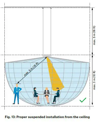
Mounting below the ceiling (suspended)
With the “Variant 3” installation option (suspended from the ceiling), we recommend adhering to the following distances during planning:
- The distance between the farthest presenter and the TCC2 is a maximum of 5 m (16 ft).
- The distance between the TCC2 and the closest standing presenter is at least 1 m (3 ft).
- The distance between the TCC2 and the floor is at least 2.50 m (8 ft).
- The distance between the suspended TCC2 and the ceiling is a maximum of 5 m (16 ft).
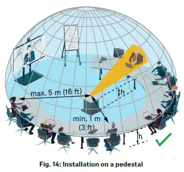
Mounting on a pedestal in the room
With the “Variant 5” installation option (on a pedestal in the room), we recommend adhering to the following distances during planning:
- The distance between the farthest presenter and the TCC2 is a maximum of 5 m (16 ft).
- The distance between the TCC2 and the closest presenter is at least 1 m (3 ft).
- The height of the podium is the same as the height of the tables in the room.
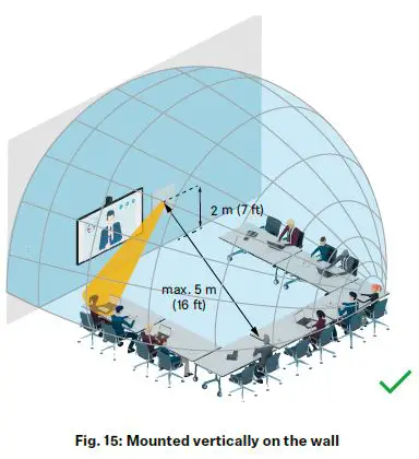
Mounting on the wall
With the “Variant 6” installation option (vertically mounted on the wall), we recommend adhering to the following distances during planning:
- The maximum distance between the presenter and the TCC2 is 5 m (16 ft).
- The distance between the TCC2 (center) and the floor is 2 m (7 ft).
- The distance between the TCC2 and the closest presenter is at least 1 m (3 ft).
Please note that for this installation plan, there should be no presenters directly in front of or with their backs to the TCC2.
Adapting to the room
Thanks to its dynamic beamforming technology, the TCC2 can adapt to almost any room configuration.
You can select individual Exclusion and Priority Zones to cause the audio beam to ignore potential sources of interference (see “Obstacles in the room”).
When planning, please ensure that no presenters will be directly in front of or with their backs to the unit once the TCC2 has been positioned.
Room examples
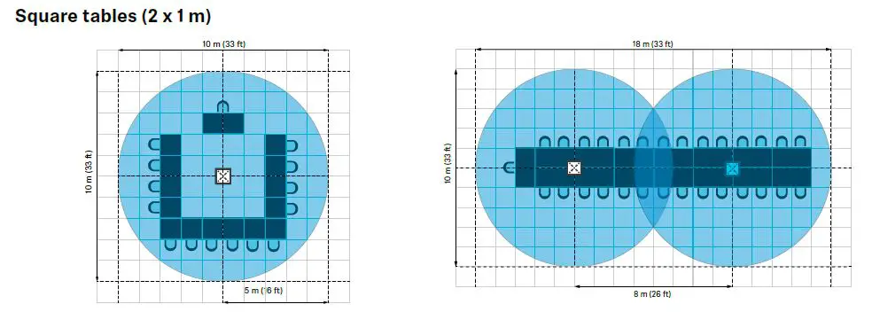
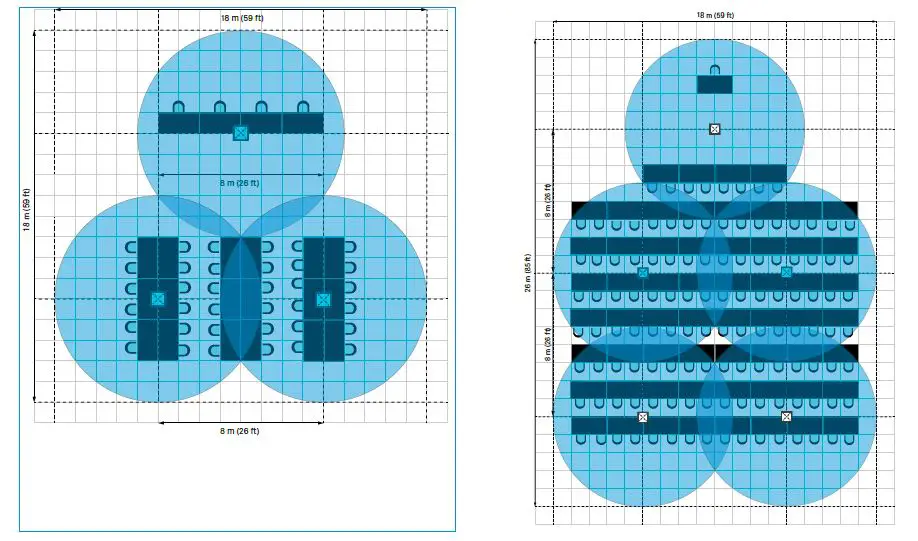
Square tables (2 x 1 m)
Ex.
- Medium-sized conference room
- Size: 100 m² (1076 ft²)
- Tables/persons: 8/16
- Required number of TCC2 units: 1
- Large conference room
- Size: 180 m² (1938 ft²)
- Tables/persons: 15/30
- Required number of TCC2 units: 2

- Extra large conference room
- Size: 325 m² (3488 ft²)
- Tables/persons: 22/44
- Required number of TCC2 units: 3
- Hall
- Size: 468 m² (5038 ft²)
- Tables/persons: 62/124
- Required number of TCC2 units: 5
Round tables (d = 2 m)
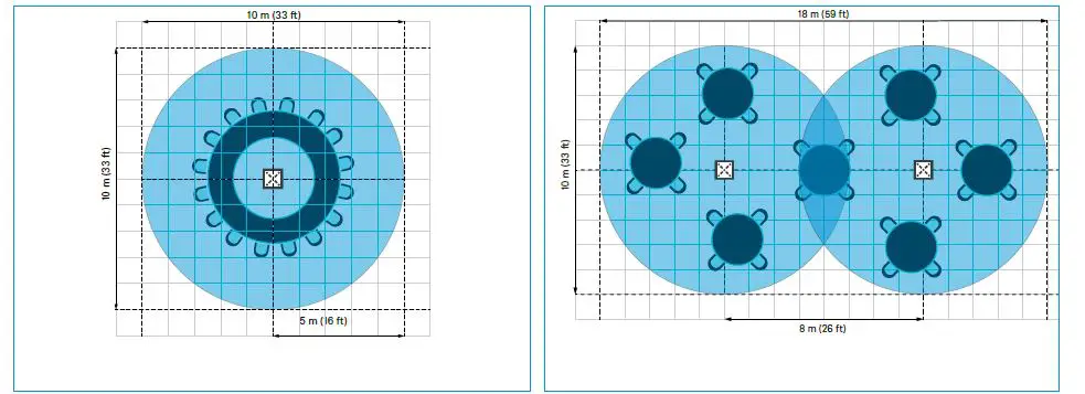
- Medium-sized conference room
- Size: 100 m² (1076 ft²)
- Tables/persons: 8/16
- Required number of TCC2 units: 1
- Large conference room
- Size: 180 m² (1938 ft²)
- Tables/persons: 7/28
- Required number of TCC2 units: 2

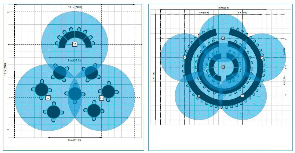
- Extra large conference room
- Size: 325 m² (3488 ft²)
- Tables/persons: 11/36
- Required number of TCC2 units: 3
- Hall
- Size: 572 m² (6167 ft²)
- Tables/persons: 26/52
- Required number of TCC2 units: 6
Positioning in the room
For maximum coverage in the room, the TCC2 should be positioned so that it covers the entire area to be detected from a central position. In some cases the preferred central position in the room’s ceiling may be occupied by lights, built-in air conditioning units or other devices. As long as the minimum distances are observed and the coverage radius is taken into account, the TCC2 can also be positioned in a non-central location.
Example:
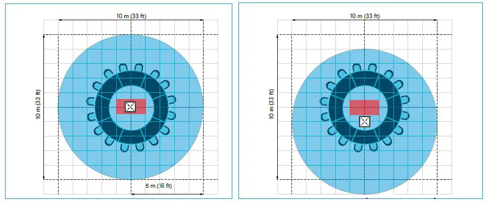
- The preferred position in the center of the ceiling is blocked by other installations and cannot be used for the TCC2.
- The TCC2 is installed in a non-central position that still ensures full coverage of the intended area.
Extending the coverage radius
If the coverage of a single TCC2 is not sufficient for the required area, you can extend the coverage radius with additional units. Note that the distance between the TCC2 devices should not exceed 7 to 8 m (23 to 26 ft).
Example:
- The intended coverage cannot be achieved with a single TCC2.
- An additional TCC2 makes it possible to cover the required area.
Obstacles in the room
Some rooms are equipped with technologies that cause additional noise or interference. Such sources of interference could be an air conditioner, a coffee machine, or the fan noise from a ceiling-mounted projector that is mounted near the ceiling microphone.
To prevent noise from these sources from being transmitted through the ceiling microphone array, you can define up to five Exclusion Zones in the Control Cockpit software. The Exclusion Zones enable you to eliminate unwanted sources of constant noise in order to optimize the audio experience.
Obstacles may be located at the edges of the room or on the ceiling.
Obstacles on walls or at the edges
If the obstacles are located on walls or at the edges of a room, the TCC2 should preferably be installed in or suspended from the ceiling.
You can then use the Control Cockpit software to identify the obstacles and exclude them from the active detection radius based on their vertical and horizontal position in the room.
Up to five Exclusion Zones can be created and activated simultaneously.
Example
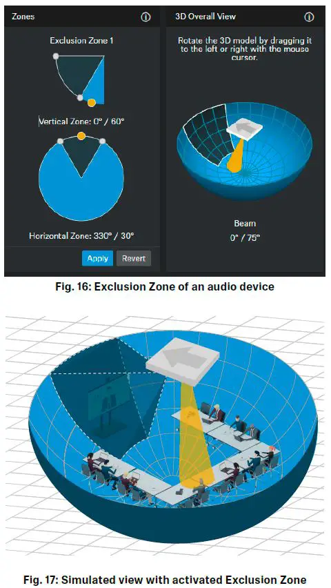
If there is a speaker mounted on the wall, the TCC2 will automatically track to that audio source. The yellow dot and conical beam in the 3D Overall View will show the exact position of the audio source.
This automatic noise detection enables you to precisely define an Exclusion Zone for this area (e.g. the area around a screen with audio output).
Once the defined Exclusion Zone is activated,incoming signals from this area are no longer picked up.
Obstacles on the ceiling
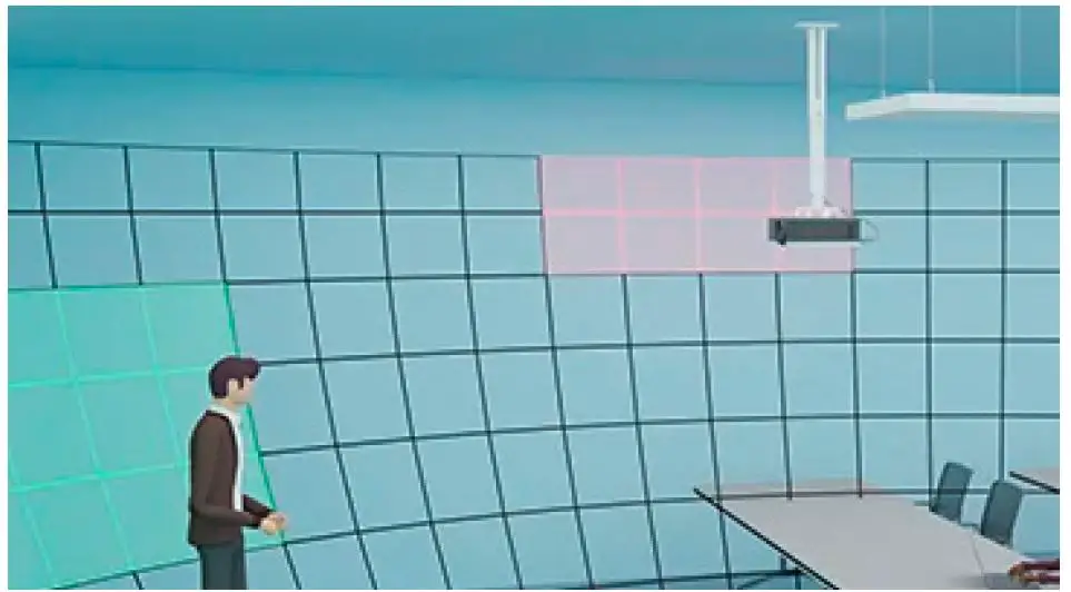
If there are obstacles on the ceiling, such as a suspended projector, they can be easily excluded from the active detection zone by specifying the exact horizontal angle and, most importantly, the vertical angle. After activating the Exclusion Zone, the audio signals from this area are no longer picked up directly, but rather only as quiet reflections in the room.
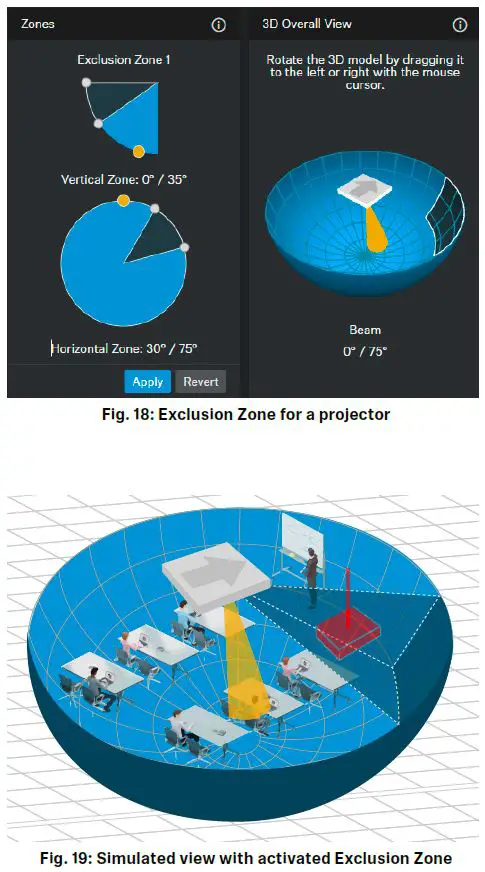
Example
In a room, a projector has already been installed in the ceiling. The TCC2 is located at least one meter away from the projector and clearly picks up the noise from the cooling fan.
The Control Cockpit software precisely localizes the incoming audio signals and visualizes them with a yellow dot under “Zones” (Fig. 18).
By defining and activating an Exclusion Zone for the localized area, the constant fan noise is not picked up directly anymore and therefore highly attenuated (Fig. 19).
Sound distribution
The recommended distances for positioning the TCC2 in the room are determined by the inverse square law (ISL).
This law states that each doubling of the distance from the sound source reduces the sound pressure level by 6 dB. This means that the sound energy decreases with the square of the distance from the sound source when distributed over a large area.
The more precisely you adhere to the minimum and maximum distances, the fewer adjustments you will have to make in the system to amplify or attenuate audio signals.
Example:
The TCC2 was installed on the ceiling at a height of 3 m (10 ft). The maximum distance to the farthest speaking person is ideally 4 m (13 ft) and should not exceed 5 m (16 ft).
If the person speaking is outside the recommended maximum distance, the audio signal may be picked up very weakly or not at all. In this case, the incoming signals would need to be amplified in the system.
Effects on the sound pressure level:
| Distance from the TCC2 | Incoming level |
| 4 m (13 ft) | 60 dB SPL |
| 5 m (16 ft) | 58 dB SPL |
| 6 m (20 ft) | 56.5 dB SPL |
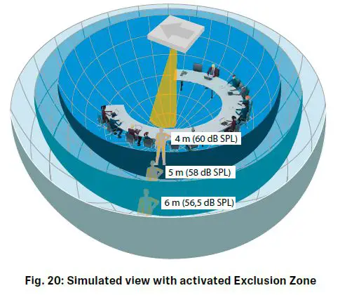
In the opposite case, the incoming level from a person standing too close to the unit will be very high and will need to be attenuated in the system.
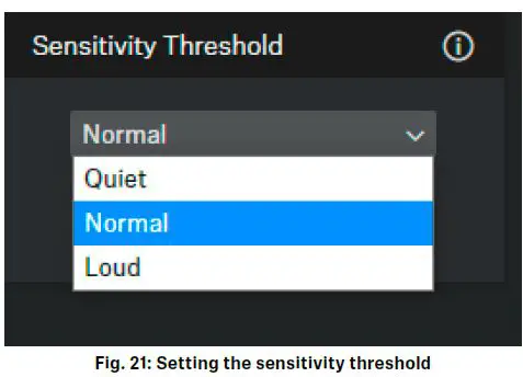
Sensitivity Threshold
The Sensitivity Threshold setting lets you adjust the TCC2 microphone’s sensitivity to background noise in order to better identify the presenter. Depending on the setting, the sensitivity is either amplified or attenuated:
• Quiet: recommended setting for presenters with low speech volume. The sensitivity of the microphone is amplified.
• Normal (factory setting): recommended setting for presenters with normal speech volume.
• Loud: recommended setting for presenters with high speech volume (e.g. in a room with a lot of background noise). The sensitivity of the microphone is attenuated.
Accessories
Sennheiser electronic GmbH & Co. KG
Am Labor 1, 30900 Wedemark, Germany, www.sennheiser.com
2023-01 | v2.0


