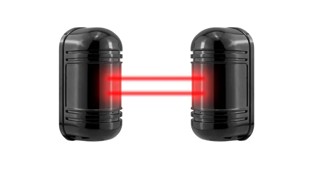
![]() TRIPLICATE PHOTOELECTRIC BARRIER
TRIPLICATE PHOTOELECTRIC BARRIER
8-Channel Frequencies IR Beam Detector
Model: 50m / 100m / 150m / 200m / 250m
Instruction Manual
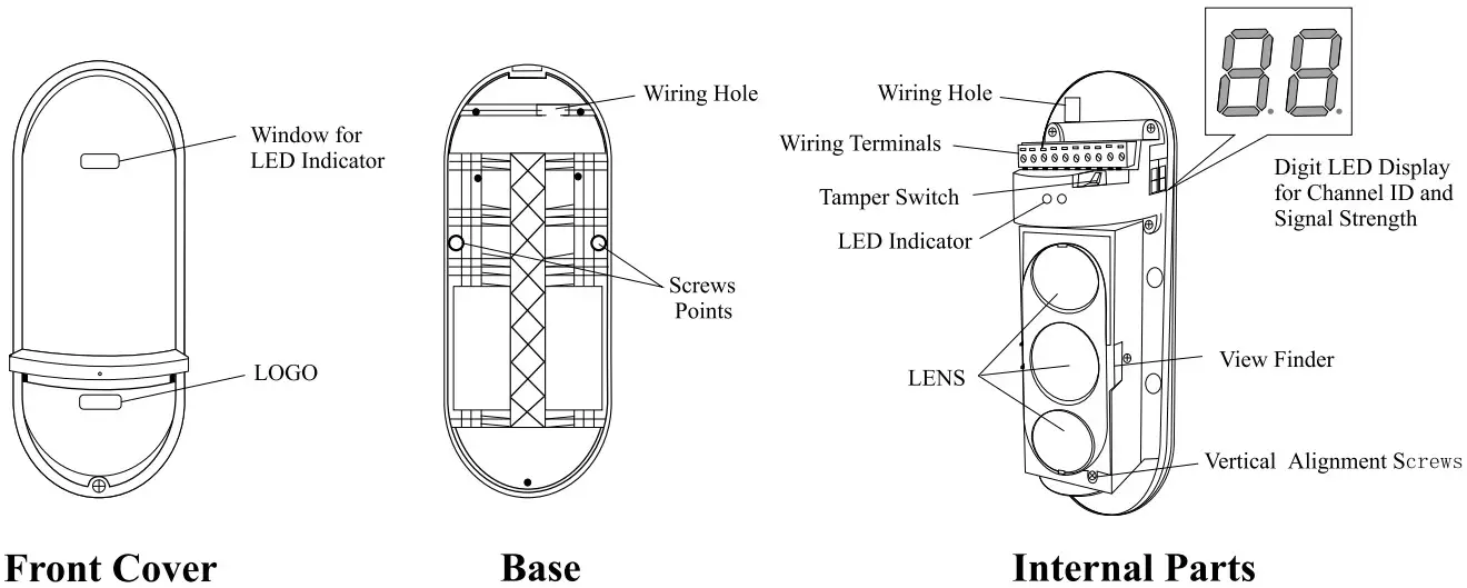
PARTS DESCRIPTION
WIRING TERMINALS & LED INDICATORS
| RECEIVER (RX) | ||||
| POWER IN | ALARM OUT | FOG ALARM | TAMPER | POWER OUT |
RECEIVER![]() Terminal 1, 2: Power Input, DC 10-36V / AC 8-24AC
Terminal 1, 2: Power Input, DC 10-36V / AC 8-24AC
Terminal 3, 4, 5: Alarm Output, N. C. / N. O.
Terminal 6, 7: Fault or Environment Alarm, N. C. (optional) When signal strength decrease slowly to 0.8v, the detector will activate the fault alarm output
Terminal 7, 8: Tamper Switch Alarm, N. C.
Terminal 9, 10: Power Output, for connecting heater or wireless module
LED Indicator: Power LED is always ON after power on and the Alarm LED is ON in alarm
| TRANSMITTER (TX) | |||
| POWER IN | / | TAMPER | POWER OUT |
| + – | / | COM NC | + – |
TRANSMITTER![]() Terminal 1, 2: Power Input, DC 10-36V / AC 8-24AC
Terminal 1, 2: Power Input, DC 10-36V / AC 8-24AC
Terminal 3, 4, 5, 6: Reserve
Terminal 7, 8: Tamper Switch Alarm, N. C.
Terminal 9, 10: Power Output for connecting heater or wireless module The power voltage is the same as the power input
LED Indicator: Power LED is always ON after power on
DIP SWITCHES & LED DISPLAY
RECEIVER
 RECEIVER LED DISPLAY
![]()
- Alignment Voltage
0.0-1.5 REALIGN
1.5-2.0 FAIR
2.0-2.5 GOOD
2.5-3.5 BEST - Frequency Channel ID
CH 1,2,3…8
TRANSMITTER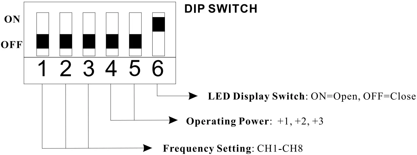 TRANSMITTER LED DISPLAY
![]() Frequency Channel ID
Frequency Channel ID
CH 1, 2, 3 …8
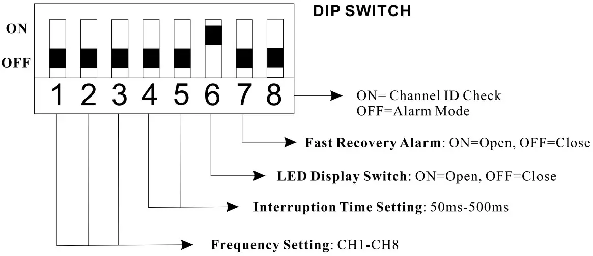
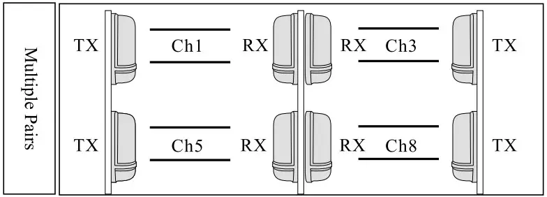
- Switch 1-3 (Receiver & Transmitter):
Frequency Setting To avoid interference with each other in multiple pairs of installation, please select different frequency channel in each pair of beam detector.
 NOTE: The frequency channel ID of the receiver and the transmitter should be the same in operation. Otherwise, the system does not work.
 - Switch 4-5 (Receiver):
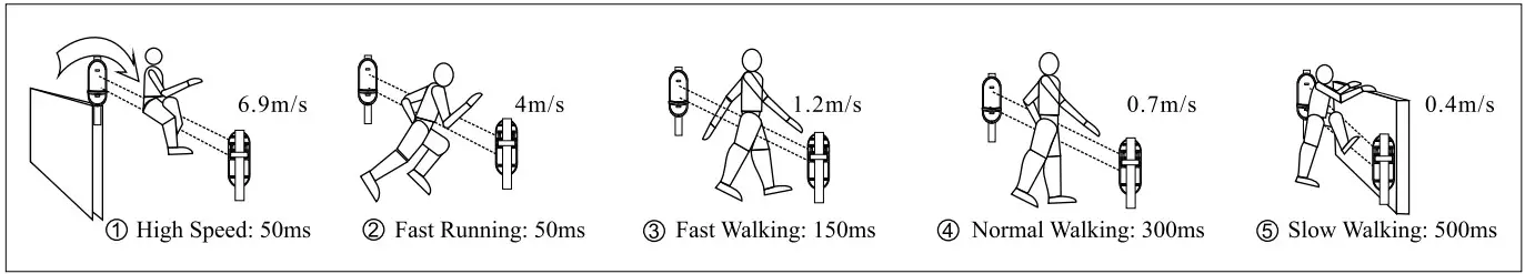
Interruption Time Setting Please make interruption time to detect different movement speed (refer to Part 6 Interruption Time Adjustment). 50ms is the most sensitive mode. Switch 4-5 (Transmitter): Operating Power
In severe environment condition, operating power mode+1, +2 or +3 makes IR beam to achieve the longest protection distance.
- Switch 6 (Receiver & Transmitter): LED ON / OFF
Close the LED Display after installation for energy saving operation.
- Switch 7 (Receiver):
When Switch 7 is ON, the alarm output is in Fast Recovery Mode. The relay opens and closes instantly when the IR beams are blocked or aligned. This function is designed for parking sensor or automatic door. When the Switch 7 is OFF, the standard alarm output period is 2 seconds. - Switch 8 (Receiver):
ON is for quick frequency channel ID checking. In this mode, there is no alarm output if the beam is triggered. Switch 8 OFF is for alarm mode and the LED display shows the signal strength value 0.0-3.5. NOTE: Switch 8 ON is for checking the frequency channel ID, please set the switch OFF in protection. Otherwise, there is no alarm output in protection. - Digit LED Display (Receiver & Transmitter)
The LED Display of the receiver shows the frequency channel ID numbers at the first 2 seconds after power on. Then the LED display shows the signal strength. If it shows the value less than 0.8, please realign the IR beam. The value 2.0-3.5 is highly recommended for the best performance in real working status. The LED Display of the transmitter shows the operating frequency channel ID only.
PRECAUTIONS
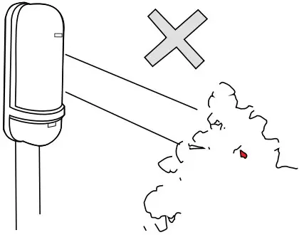
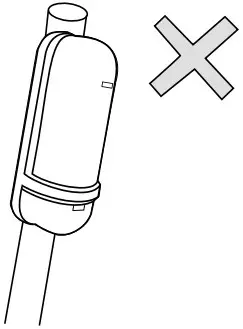
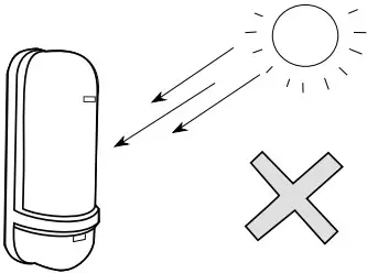
- Please do not install the system to the following location:


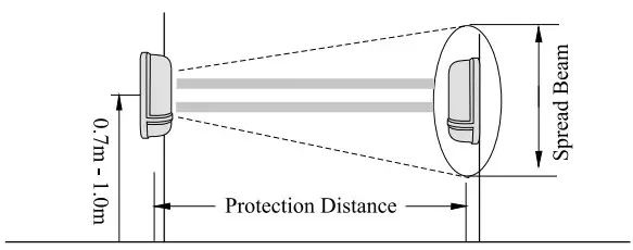
Where there is blocking objects between Receiver and Transmitter Where the installation base is unstable Where there is direct sunlight to the detector - Installation Height

- Protection Distance
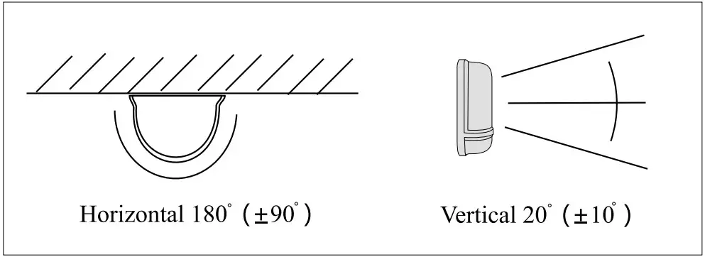
Model Distance Spread Beam 50 50M I .4M 100 100M 2.8M 150 150M 4.2M 200 200M 5.6M 250 250M 7.0M - Alignment Angle

- Stacking Installation
INSTALLATION GUIDE
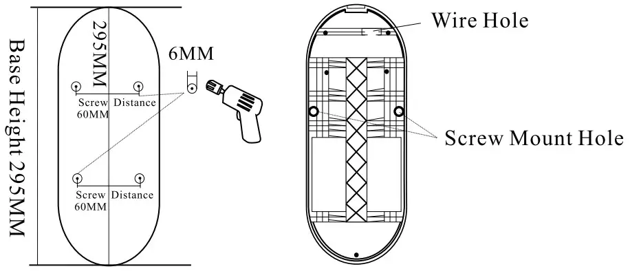
Wall Mount
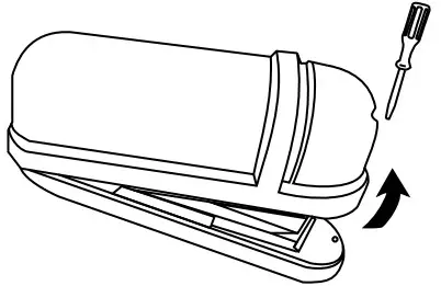
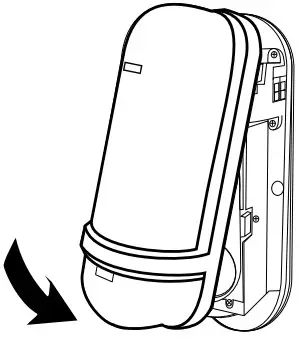
- Loose the screw and open the cover

- Drill the mounting holes on the wall and fix the base by the screw

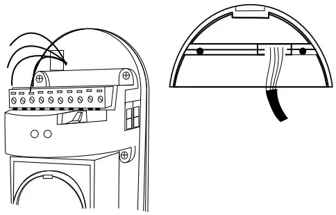
- Wiring the terminals from the hole and replace

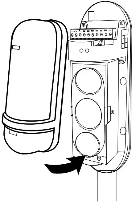
- After setting, replace the cover and tighten the screw waterproof rubber

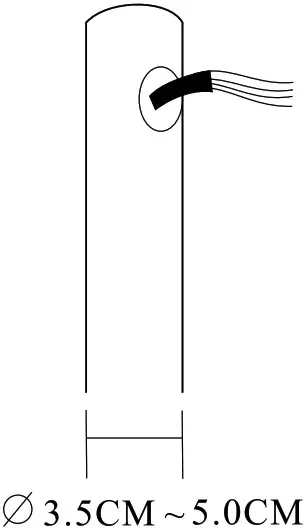
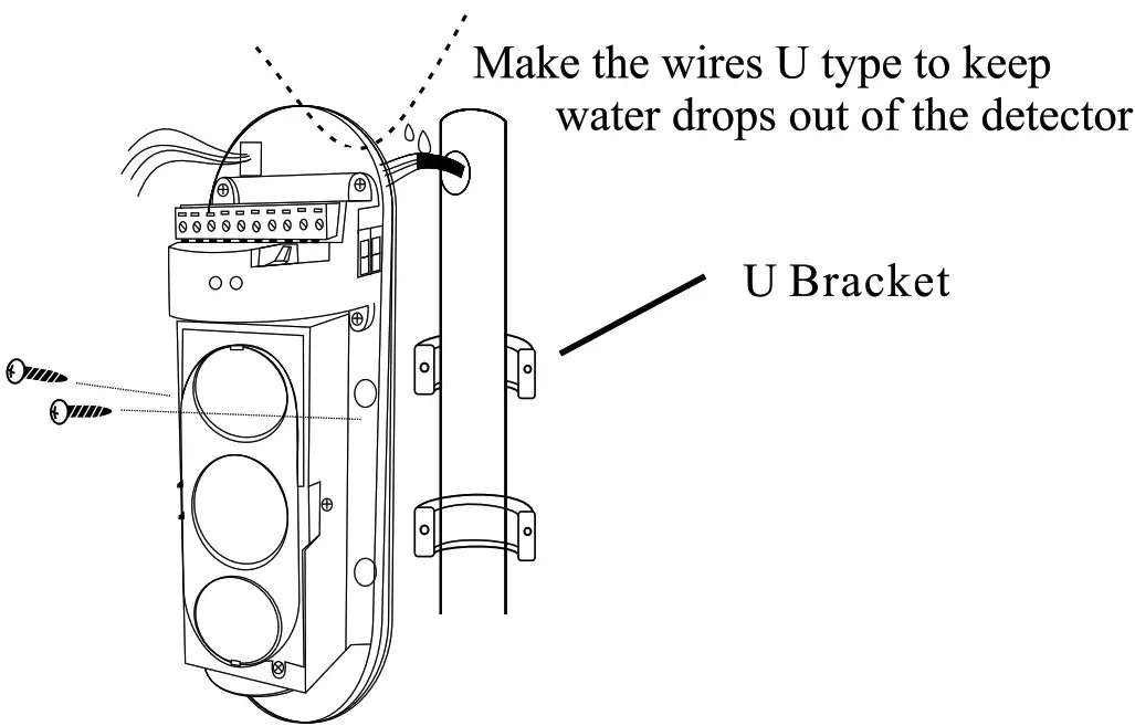
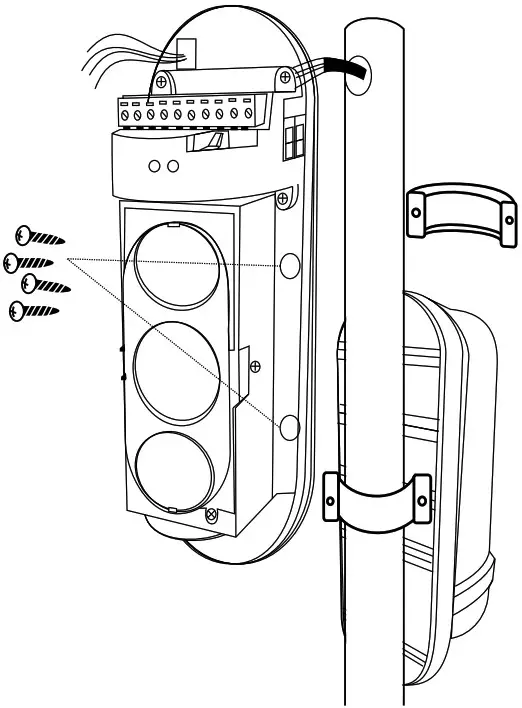
Pole Mount
- Pull out the wires from the pole hole

- Wiring the terminals and fix the base on the pole by the U Bracket

- Make back to back installation on the same pole

- After setting, replace the cover and tighten the screw

INTERRUPTION TIME ADJUSTMENT
SPECIFICATION
| Model | 50 | 100 | 150 | 200 | 250 |
| Distance (Outdoor) | 50m | 100m | 150m | 200m | 250m |
| Distance (Indoor) | 150m | 300m | 450m | 600m | 750m |
| Detection System | Simultaneous blocking of 3 infrared beams | ||||
| Response Time | 50msec, 150mse, 300mse, 500msec selectable | ||||
| Power Input | DC 10-36 / AC 8-24V | ||||
| Current Consumption | 55mA | 55mA | 60mA | I 60mA | 60mA |
| Alarm Output | Form C, Contact capacity: AC / DC30V, 0.5A or less | ||||
| Tamper Switch | N.C. open when cover is removed | ||||
| Fault Alarm(optional) | N.C. Fault Output when the signal is incompetent | ||||
| LED | Red LED Alarm (receiver), Digit LED Display | ||||
| Alignment Angle | ± 10° vertical, ± 90° horizontal | ||||
| Ambient Temperature | – 25°C to 55°C | ||||
| Relative Humidity | 95% or less | ||||
| Mount Method | Wall or Pole | ||||
| Weight | 1200g | ||||
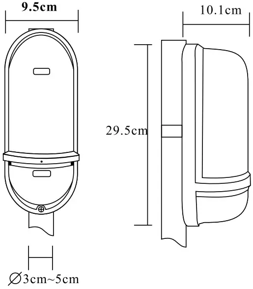
DIMENSION