![]() Accessories
Accessories
Installation Guide
Accessories
This guide provides an overview of CR7™ and CR12™ field computer connections as well as drawings that illustrate the cab connections for various machine configurations.
Important Safety Information
This is a safety alert symbol. When the symbol below appears on the device, be alert and attentive because there is the potential for personal injury.![]()
Follow the recommended precautions and safe operation practices.
Install the Display
- Mount the antenna on the centerline of the tallest point of the vehicle (usually on the top of the vehicle cabin) using the magnetic mount. Make sure that the antenna has a clear, 360° view of the sky.
Note: If the mounting location is non-magnetic, use a mounting plate to mount the antenna. - Route the Power/GPS cable to the back of the field computer and connect it to the Power/GPS connection.
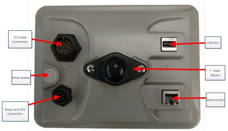
CR7™ Back
The image below shows the connections on the back of the CR7™ that will be used for installation. Note that, depending on machine configuration, some of these connections may not be used. See “System Diagrams” on page 4 for additional information on cabling.
CR12™ Back
The image below shows the connections on the back of the CR12™ that will be used for installation. Note that, depending on machine configuration, some of these connections may not be used. See “System Diagrams” on the next page for additional information on cabling.
 - Use the provided RAM® Mount arm to install the field computer inside the cab.
- For additional cabling and connection assistance, refer to the CR7™ and CR12™ Installation Guide and “System Diagrams” on the next page.
 See “System Diagrams” on page 4 for additional information on cabling.
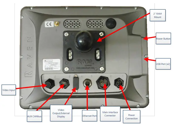 See “System Diagrams” on the next page for additional information on cabling.
http://portal.ravenprecision.com/
System Diagrams
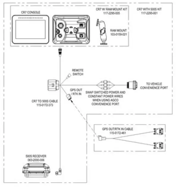
CR7™ System Diagrams
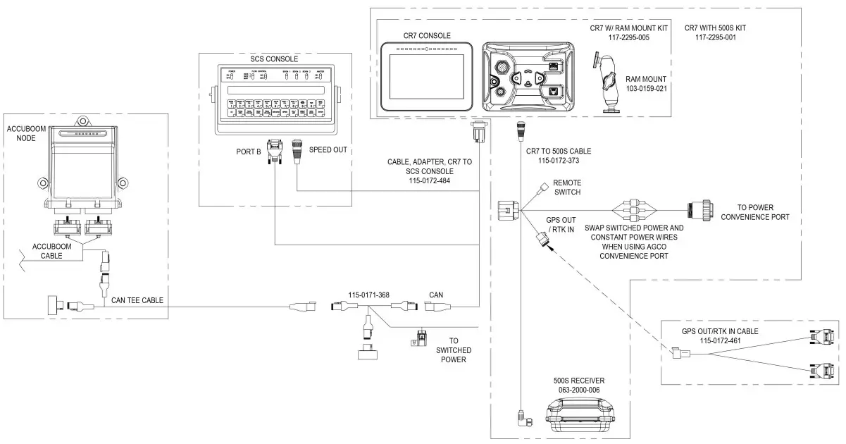
The illustrations below show CR7™ wiring diagrams for various cabling generations with optional accessories and are for reference only.
| CR7™ With 500S Smart Antenna Kit | Gen II Cabling CR7™SmarTrax™/AccuBoom™ Only |
 | 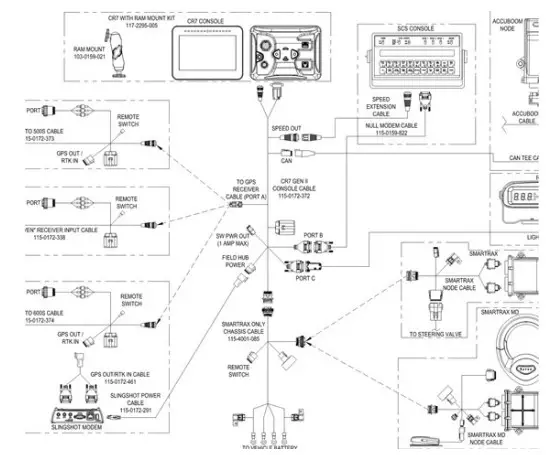 |
| Full Gen II Cabling CR7™SmarTrax™/AccuBoom™ | Gen 3 or IBBC Cabling CR7™SmarTrax™/AccuBoom™ |
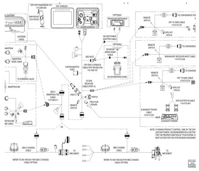 |  |
| Gen 3 or IBBC Cabling CR7™SmarTrax™ ISO Product Control | |
 | |
CR12™ System Diagrams
The illustrations below show CR12™ wiring diagrams for various cabling generations with optional accessories and are for reference only.
CR12™ Basic Installation
Glossary
| A | APN | Access Point Name |
| AprilTag | A specific system of fiducial markers is used in robotics with visual or perception systems. OMNiDRIVE™ utilizes an AprilTag marker on the hood of the tractor with the Perception Controller. | |
| B | baseline | In RTK correction systems, the baseline is the range between the base and the rover. A maximum baseline defines the range between the base and the rover before RTK corrections begin to lose precision. Alternatively in some Raven field computers, a baseline is a segment of a boundary that can be used to create guidance lines and application zones. |
| C | COG | Course Over Ground |
| controlling combine | The combine may assign paths to and may sync with, the OMNiDRIVE™ tractor. One controlling combine is required for all OMNiDRIVE™ locations. | |
| D | dBm | decibel milliwatt |
| DGPS | Differential Global Positioning System is an enhancement to standard GNSS/GPS messages to provide better position accuracy. | |
| Differential | Differential Global Positioning System is an enhancement to standard GNSS/GPS messages to provide better position accuracy. | |
| DTC | Diagnostic Trouble Code | |
| E | E-Stop | Emergency stop button or switch. |
| ECU | Electronic Control Unit | |
| ESN | Electronic Serial Number | |
| ESRI | Environmental Systems Research Institute | |
| EULA | End User License Agreement | |
| F | FNRP | Forward, Neutral, Reverse, Park |
| G | GFF | Grower, Farm, Field |
| GIS | Geographic Information System | |
| GLONASS | Global Navigation Satellite System | |
| GNSS | Global Navigation Satellite System | |
| H | HDOP | Horizontal Dilution of Precision |
| HDU | Hydraulic Drive Unit | |
| homologation | Approval or certification of devices (especially electrical and communications devices) for use in specific regions or countries. | |
| I | IBBC | Implement Bus Breakaway Connector. Connects to the IBIC on the towed implement. |
| IBIC | Implement Bus Implement Connector. Connects to the IBBC mounted on the tractor or tow implement. | |
| IMEI | International Mobile Station Equipment Identity | |
| IVT | Infinitely Variable Transmission | |
| L | lightbar | (a.k.a. light bar) Provides guidance control and display for swathing applications. |
| M | mid-point | Mid-points are points through which the cart must pass on the way to the stage or unload points. Mid-points may be used during route planning to adjust the route to keep the cart away from obstacles or to help point the tractor in the desired direction at the stage or unload points. |
| multipath | error induced in GNSS corrections due to signals arriving at the GNSS antenna after reflecting off of or diffusing from objects around the vehicle. | |
| N | NMEA | National Marine Electronics Association |
| non-controlling combine | A combine operating with the OMNiDRIVE™ tractor and controlling combine. A noncontrolling combine may share harvest coverage data to the coverage map during a harvest job, but cannot sync with or plan routes for the OMNiDRIVE™ tractor. | |
| O | object pool | The user interfaces for a system or feature connected to an ISOBUS UT. |
| OLAF | Online Activation Form | |
| OTA | (Over the Air) Software updates and other information are pushed from Slingshot® servers via the Slingshot® system. | |
| P | prescription map | Variable Rate Application utilizes a prescription (Rx) map for a given field and product to automatically adjust the rate of application based on the target rate zones within the field. The .shp, .shx, and .dbf files required to create a shapefile prescription map must be in a polygon shape format that complies with the ESRI (Environmental Systems Research Institute) shapefile specifications and must also be in the WGS (World Geodetic System) 84 datum. |
| PRN | Pseudo-Random Number | |
| PST | PowerShift Transmission | |
| R | RSSI | Received Signal Strength Indicator |
| RTK | Real-time Kinematic | |
| Rx map | Variable Rate Application utilizes a prescription (Rx) map for a given field and product to automatically adjust the rate of application based on the target rate zones within the field. The .shp, .shx, and .dbf files required to create a shapefile prescription map must be in a polygon shape format that complies with the ESRI (Environmental Systems Research Institute) shapefile specifications and must also be in the WGS (World Geodetic System) 84 datum. | |
| S | scout map | A map of field features or areas of interest in a field. Field features may include, but are not limited to field boundaries, weed or insect infestations, tile lines or waterways, rocks and rock piles, trees, spray or no-spray zones, etc.) |
| shapefile | A shapefile is a vector format consisting of a .shp, .shx, and .dbf file and is used to store geospatial data and information such as field boundaries, product application coverage, and waypoints. | |
| SHCS | Socket Head Cap Screw | |
| SIM | Subscriber Identification Module | |
| SNR | Signal-to-Noise Ratio | |
| SOG | Speed Over Ground | |
| SSID | Service Set Identifier | |
| stage point | The location where the grain cart will stop and wait to sync with the combine. During harvesting, move the staging point to ensure the tractor is positioned conveniently for efficient syncing with the combine. | |
| T | task controller | A software feature of an ISOBUS network that automates a system or logs data from various field operations. The capabilities of a task controller vary but may offer some simple control features such as automatic section control or more complex features for prescription rate control, etc. |
| U | unload point | The location where the grain cart will stop and wait to be unloaded into a grain truck. Move the unload point if the location where trucks will access the field changes. |
| UT | A Universal Terminal (formerly Virtual Terminal) is an electronic display or console capable of interfacing with ECUs on an ISOBUS network. | |
| V | VRA | Variable Rate Application utilizes a prescription (Rx) map for a given field and product to automatically adjust the rate of application based on the target rate zones within the field. The .shp, .shx, and .dbf files required to create a shapefile prescription map must be in a polygon shape format that complies with the ESRI (Environmental Systems Research Institute) shapefile specifications and must also be in the WGS (World Geodetic System) 84 datum. |
| VT | A Universal Terminal (formerly Virtual Terminal) is an electronic display or console capable of interfacing with ECUs on an ISOBUS network. | |
| W | WGS | World Geodetic System |
| working set | The user interfaces for a system or feature connected to an ISOBUS UT. | |
![]()


