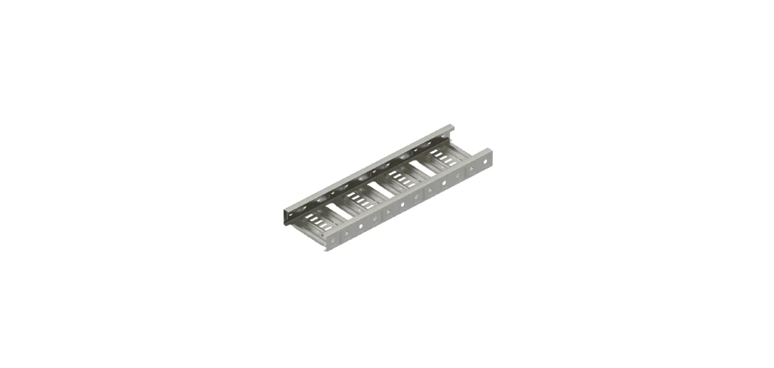
Clenergy RUNNUR CR1 Cable Tray Installation
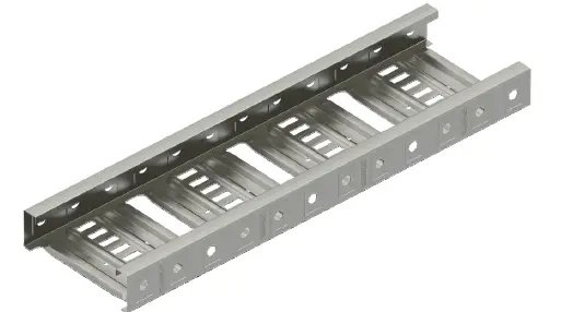
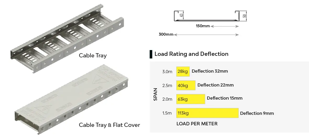
Cable Tray
Notes
- CR1 has been tested in accordance with NEMA VE1 standard by a NATA certified testing facility. The deflection for continuous span is based on physical test results for easy reference. However, it cannot be applied to end spans. Please refer to NEMA VE2 installation guidelines for cable tray installations.
- Supplied in 3m length.
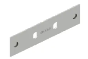
Cable Tray Accessories
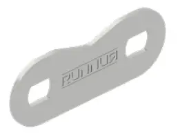
- CR1-SPM Splice Plate

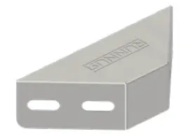
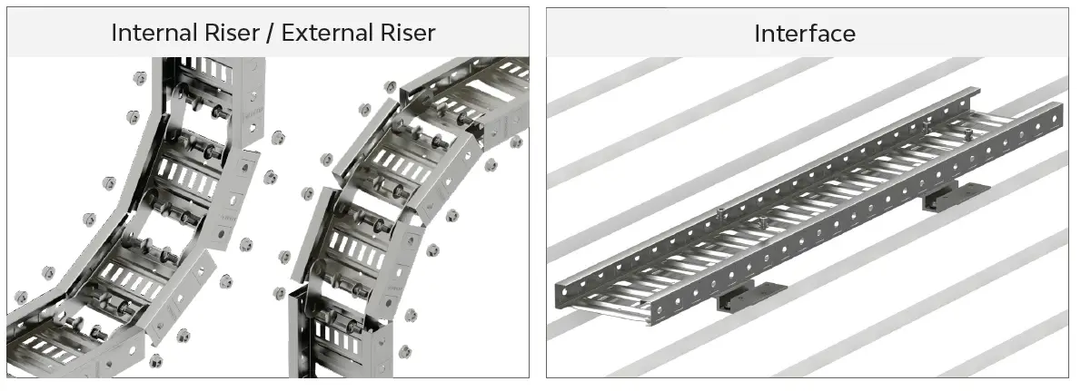
- CR1-RM Riser Link

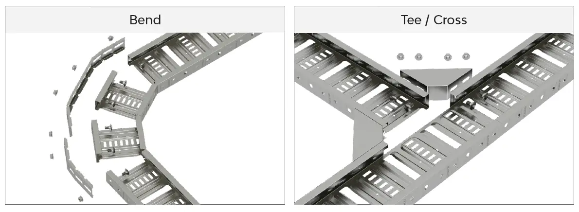
- CR1-TM Tee/Cross Braket

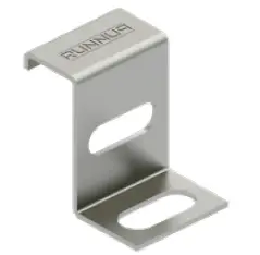
- CR1-HM Hold Down Unit

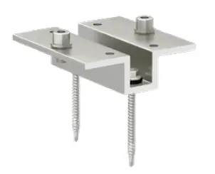
- CR-I-01 Tin Interface for Cable Tray

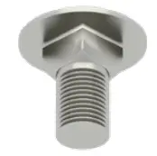
- CR-SBS Splice Bolt M10*18

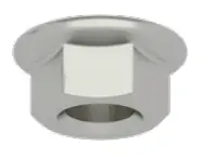
- CR-CS Counterbore Nut

Storage
Zn-Mg-Al coating steel cable tray and cover can be stored outside, but should be loosely stacked, elevated off the ground, and placed in a well-ventilated dry location. If appearance is important, cable tray and cover should be stored indoors to prevent water or other foreign materials staining.
Installation Method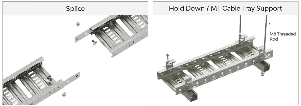
@runnurcabletrays @Clenergy @runnur T: 03 9239 8088 | E: [email protected] | W: www.runnur.com.au


