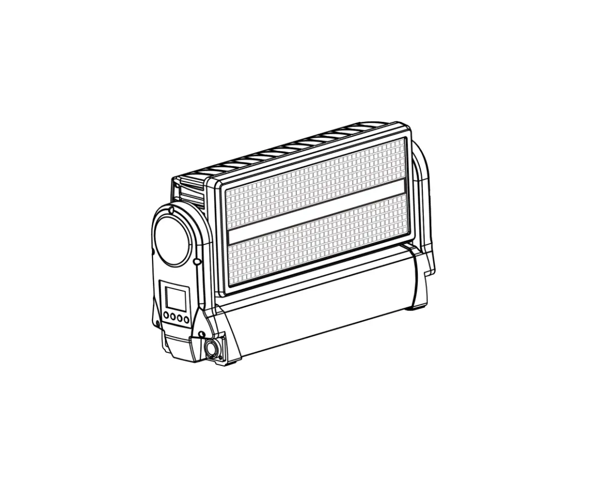
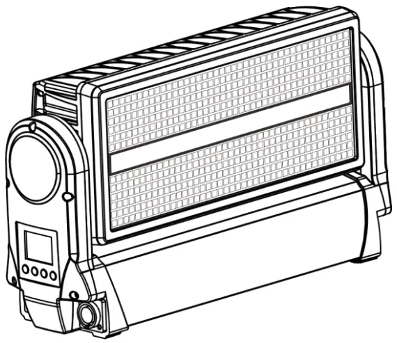
ARTFOX L8 FORUM LED Strobe Wash Outdoor Moving Light
| This product manual contains important information about the safe installation and use of this projector. Please read and follow these instructions carefully and keep this manual in a safe place for future referen |
Please read the instructions carefully before use
STATEMENT
The product has well capability and intact packing when leave factory. All of the user should comply with warning item and manual, any misuse cause of the damages are not included in our guarantee, and also can not be responsible for any malfunction & problem owing to ignore the manual.
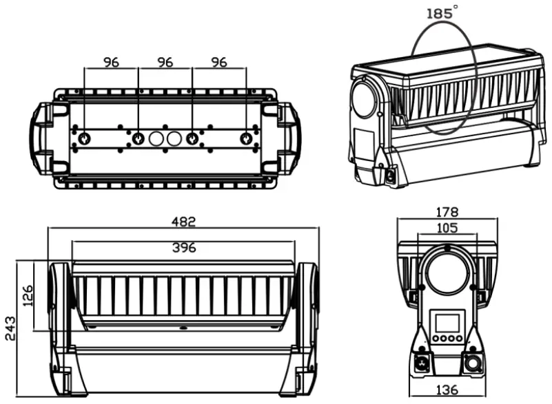
Dimension
Safety Informations
 | WARNING! Read the safety precautions in this section before unpacking, installing, powering or operating this product. |
This luminaries are multi-environmental fixtures with an IP-rating of 65, intended for professional use only. They are not suitable for household use.
Review the following safety precautions carefully before installing or operating the fixture. This fixture must be installed in accordance with the applicable installation code by a person familiar with the construction and operation of the fixture and the hazards involved.
Preventing electric shock
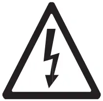 | WARNING! Risk of electric shock. |
- Always power off/unplug the fixture before removing any covers.
- Ensure that the power is turned off when connecting the fixture to the AC mains supply.
- Ensure that the fixture is electrically connected to earth (ground).
- Do not apply power if the fixture is in any way damaged.
- Do not immerse the fixture in water or liquid.
Preventing burns and fire
 | WARNING! Take measures to prevent burns and fire. |
- Install in a location that prevents accidental contact with the fixture.
- Install only in a well-ventilated space.
- Install at least 0.3 m (12 in.) away from objects to be illuminated.
- Install only in accordance with applicable building codes.
- Ensure a minimum clearance of 0.1 m (4 in.) around the cooling fans.
- Do not paint, cover or modify the fixture.
- Keep all flammable materials away from the fixture.
- Allow the fixture to cool for 15 minutes after operation, before touching it.
- CAUTION: Exterior surface temperature after 5 min. operation = 45 °C (113 °F). Steady state = 60 °C (140 °F)
Avoid personal injury
 | WARNING! Take measure to prevent personal injury |
- Do not look directly at the light source from close range.
- Take precautions to prevent injury due to falls when working at height.
- For permanent installation, ensure that the fixture is securely fastened to a load-bearing surface with suitable corrosion-resistant hardware.
- For temporary installation with clamps, ensure that the quarter-turn fasteners are turned fully and secured with a suitable safety cable. The cable must be approved for a safe working load (SWL) of 10 times the weight of the fixture, and it must have a minimum gauge of 3 mm.
Preparing for installation
Unpack the fixture and inspect it to ensure that it has not been damaged during transport.
The fixture is shipped with two quarter-turn brackets, that can be used to mount the fixture at elevation.
The fixture is IP65-rated, and is designed for use in wet locations. This means that it is protected from:
- Dust, to the degree that dust cannot enter the fixture in sufficient quantities as to interfere with its operation.
- Lower pressure jets of water from any direction.
When selecting a location for the fixture, ensure that:
- It is situated away from public thoroughfares and protected from contact with people.
- It is not immersed in water or exposed to high-pressure water jets.
- It has adequate ventilation.
Installation
The fixture may be installed in any orientation, but if installed horizontally with a downward beam-angle, water can potentially pool in the fan wells. Under normal operation the moisture will evaporate. However, in locations with high rainfall, you may wish to fabricate a rain shield above the fixture, or modify the position and orientation of the fixture to minimize pooling.
Two quarter-turn brackets are supplied with the fixture if it is to be flown above the ground. Rig the fixture to a support truss or structure using the supplied brackets and suitable clamps.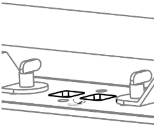
Fasten a safety cable (not shown) between the support structure and the attachment point on the fixture. The safety cable must be able to bear at least 10 times the weight of the fixture.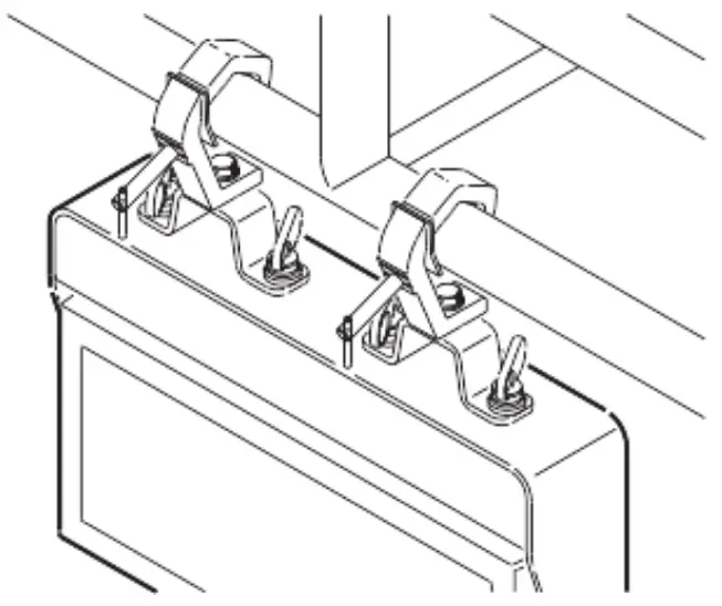
Connecting AC Power
The fixture can operate on any 100240 V, 50/60 Hz AC mains power supply. It draws approximately 2 amps at full power. For permanent installation, have a qualified electrician wire the mains cable directly to a suitable branch circuit. The junction’s ingress protection (IP) rating must be suitable for the location. For temporary installation, the mains cable may be fitted with a grounded connector intended for exterior use.
When installing standard type C circuit breakers there will be no limitations due to the fixture in-rush current. Due to the nominal current of the fixture, ensure that no more than:
4 fixtures are connected through the same type C, 10A circuit breaker.
7 fixtures are connected through the same type C, 16A circuit breaker.
The fixture must be grounded/earthed and be able to be isolated from AC power. The AC power supply must incorporate a fuse or circuit breaker for fault protection.
After connecting the fixture to power, run the on-board test, using the “Fixture Text” menu, to ensure that the fixture and each LED are functioning correctly. See “Control menu” on page 13.
CAUTION: Do not open the fixture to replace the supplied power cable, or connect the fixture to an electrical dimmer system, as this can damage it.
Configuring the fixture
Set up the fixture using the control panel and LCD display at the arm side of the fixture.
Navigate the menus and options using the arrow buttons and select items using the Enter button. The options available are listed in “Control menu” on page 13.
After powering on, the display shows the currently selected operating mode and other information.
The fixture is set by default to be controlled in DMX mode.
Master/Slave configuration
You can set a fixture to operate as master fixture to another fixture (which then becomes a slave fixture), or an entire group of fixtures (which then becomes slave fixtures). The assigned slave fixture(s) will mimic the settings of the master fixture. Use the “Auto Program -> Auto Color / Auto Fade” menu to set your fixture as master fixture, then other fixtures set to DMX mode as slave fixture.
Setting a static color manually
The fixture can be configured to display a predefined and static color using the “Manual Color” (see “Control menu” on page 13).
It may suit your needs when you without a DMX controller to do the color mixing.
Using stand-alone operation
Stand-alone operation is where the fixture is not connected to a control device, but is preprogrammed with 2 modes (Auto Color, Auto Fade), that play continuously in a loop, the run speed of “Auto Color”, “Auto Fade” are adjustable.
To define a stand-alone program, use the “Auto Program” menus (see “Control menu” on page 13).
Connecting to a DMX control device
The fixture is controllable using a DMX control device and it can be connected using a DMX cable.
If using a cabled DMX system, connect the DMX in cable (with male 3-pin XLR plug) and out cable (with female 3-pin XLR plug) to the DMX data link. Terminate the DMX out cable of the last fixture in the data link. For outdoor installations, use only IP-rated XLR connectors suitable for outdoor use.
The DMX512 is widely used in intelligent lighting control, with a DMX 512 controller. connect several lights together, DMX in and DMX out, 3 pin XLR connectors: Pin 1: GND, Pin 2: Negative signal (-), Pin 3: Positive signal (+)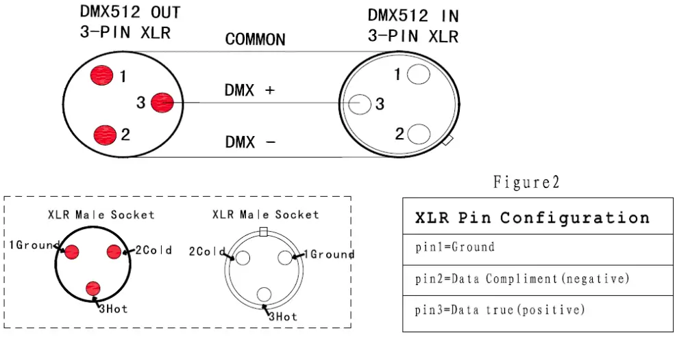
Configuring the fixture for DMX control
About DMX
The fixture can be controlled using signals sent by a DMX controller on a number of channels (which varies depending on the DMX mode that has been set).
The first channel used to receive data from a DMX control device is known as the DMX start address. Each fixture must have a DMX start address set. For example, if a fixture has a DMX address of 10 and it is in 4-channel DMX mode, then it uses channels 10, 11,12 and 13. The following fixture in the DMX chain could then be set to a DMX address of 14. If two or more DMX fixtures of the same type have the same DMX address, then they will mimic each other’s behaviour. Incorrect settings will result in unpredictable responses to the lighting controller.
Setting the DMX address
The DMX address can be seen on the main screen. To change the address setting, press the up arrow to increase the address, or the down arrow to decrease the setting. When the desired address is displayed, press Enter to save the setting.
Note that channel spacing is determined by the DMX mode. See the “DMX protocols” on page 11 for specific DMX control values.
Setting the DMX mode
Using the “DMX Channel Mode” menu available from the control panel, specify the DMX mode that provides the fixture controls that you require, confirm chosen mode by pressing `Enter’.
Cleaning
To maintain optimal performance, regular cleaning is essential. Cleaning schedules will vary depending on the operating environment, and the installation should therefore be checked at frequent intervals within the first few weeks of operation to see whether cleaning is necessary. This procedure will allow you to assess cleaning requirements in your par- ticular situation. Clean the fixture using a soft cloth dampened with a solution of water and a mild detergent. Do not use products that contain solvents, abrasives or caustic agents for cleaning, as they can cause damage to both hardware, cables and connectors.
DMX protocols
Configuring DMX is described “Setting the DMX mode” on page 10.
7 Channel mode
| Channel | Name | DMX Value | Description |
| 1 | Tilt | 0-255 | Tilt Movement |
| 2 | Beam Dimmer | 0-255 | Beam Intensity |
| 3 | Beam Strobe Mode | 0-5 | No Strobe |
| 6-42 | Strobe Mode 1 | ||
| 43-85 | Strobe Mode 2 | ||
| 86-128 | Strobe Mode 3 | ||
| 129-171 | Strobe Mode 4 | ||
| 172-214 | Strobe Mode 5 | ||
| 215-255 | Strobe Mode 6 | ||
| 4 | Plate Red | 0-255 | Plate Red Dimmer |
| 5 | Plate Green | 0-255 | Plate Green Dimmer |
| 6 | Plate Blue | 0-255 | Plate Blue Dimmer |
| 7 | Plate Strobe | 0-9 | No Strobe |
| 10-255 | Strobe from slow to fast |
14 Channel mode
| Channel | Name | DMX Value | Description |
| 1 | Tilt | 0-255 | Tilt Movement |
| 2 | Tilt Fine | 0-255 | Tilt Fine Movement |
| 3 | Beam Dimmer | 0-255 | Beam Intensity |
| 4 | Beam Strobe Mode | 0-5 | No Strobe |
| 6-42 | Strobe Mode 1 | ||
| 86-128 | Strobe Mode 3 | ||
| 129-171 | Strobe Mode 4 | ||
| 172-214 | Strobe Mode 5 | ||
| 215-255 | Strobe Mode 6 | ||
| 5 | Reserved | Reserved Channel | |
|
6 |
Beam Macro | 0-15 | Beam Off |
| 16-57 | Beam Macro 1 | ||
| 58-99 | Beam Macro 2 | ||
| 100-141 | Beam Macro 3 | ||
| 142-183 | Beam Macro 4 | ||
| 184-225 | Beam Macro 5 | ||
| 226-255 | Beam Macro 6 | ||
| 7 | Plate Red | 0-255 | Plate Red Dimmer |
| 8 | Plate Green | 0-255 | Plate Green Dimmer |
| 9 | Plate Blue | 0-255 | Plate Blue Dimmer |
| 10 | Plate Strobe | 0-9 | No Strobe |
| 10-255 | Strobe from slow to fast | ||
| 11 | Plate Macro | 0-4 | Plate Macro Off |
| 5-9 | Plate Macro 1 | ||
| 10-14 | Plate Macro 2 | ||
| 15-19 | Plate Macro 3 | ||
| … | Plate Macro … | ||
| 250-254 | Plate Macro 50 | ||
| 255 | Plate Macro 51 | ||
| 12 | Plate Macro Color | 0-255 | Plate Macro Color |
| 13 | Plate Macro Speed | 0-255 | Speed From Slow To Fast |
| 14 | Reserved | 0-255 | Reserved Channel |
15 Channel mode
| Channel | Name | DMX Value | Description |
| 1 | Tilt | 0-255 | Tilt Movement |
| 2 | Tilt Fine | 0-255 | Tilt Fine Movement |
| 3 | Beam Dimmer | 0-255 | Beam Intensity |
| 4 | Beam Strobe Mode | 0-5 | No Strobe |
| 6-42 | Strobe Mode 1 | ||
| 43-85 | Strobe Mode 2 | ||
| 86-128 | Strobe Mode 3 | ||
| 129-171 | Strobe Mode 4 | ||
| 172-214 | Strobe Mode 5 | ||
| 215-255 | Strobe Mode 6 | ||
| 5 | Reserved | Reserved Channel | |
| 6 | Beam Macro | 0-15 | Beam Off |
| 16-57 | Beam Macro 1 | ||
| 58-99 | Beam Macro 2 | ||
| 100-141 | Beam Macro 3 | ||
| 142-183 | Beam Macro 4 | ||
| 184-225 | Beam Macro 5 | ||
| 226-255 | Beam Macro 6 | ||
| 7 | Plate Red | 0-255 | Plate Red Dimmer |
| 8 | Plate Green | 0-255 | Plate Green Dimmer |
| 9 | Plate Blue | 0-255 | Plate Blue Dimmer |
| 10 | Plate Strobe | 0-9 | No Strobe |
| 10-255 | Strobe from slow to fast | ||
| 11 | Plate Macro | 0-4 | Plate Macro Off |
| 5-9 | Plate Macro 1 | ||
| 10-14 | Plate Macro 2 | ||
| 15-19 | Plate Macro 3 | ||
| … | Plate Macro … | ||
| 250-254 | Plate Macro 50 | ||
| 255 | Plate Macro 51 | ||
| 12 | Plate Macro Color | 0-255 | Plate Macro Color |
| 13 | Plate Macro Speed | 0-255 | Speed From Slow To Fast |
| 14 | Tilt Speed | 0-255 | Tilt Speed From Fast To Slow |
| 15 | Dimmer Speed | 0-255 | Dimmer Speed From Fast To Slow |
42 Channel mode
| Channel | Name | DMX Value | Description |
| 1 | Tilt | 0-255 | Tilt Movement |
| 2 | Tilt Fine | 0-255 | Tilt Fine Movement |
| 3 | Beam Dimmer | 0-255 | Beam Intensity |
|
4 |
Beam Strobe Mode | 0-5 | No Strobe |
| 6-42 | Strobe Mode 1 | ||
| 43-85 | Strobe Mode 2 | ||
| 86-128 | Strobe Mode 3 | ||
| 129-171 | Strobe Mode 4 | ||
| 172-214 | Strobe Mode 5 | ||
| 215-255 | Strobe Mode 6 | ||
| 5 | Reserved | 0-255 | Reserved Channel |
|
6 |
Beam Macro | 0-15 | Beam Off |
| 16-57 | Beam Macro 1 | ||
| 58-99 | Beam Macro 2 | ||
| 100-141 | Beam Macro 3 | ||
| 142-183 | Beam Macro 4 | ||
| 184-225 | Beam Macro 5 | ||
| 226-255 | Beam Macro 6 | ||
| 7 | Plate Red | 0-255 | Plate Red Dimmer |
| 8 | Plate Green | 0-255 | Plate Green Dimmer |
| 9 | Plate Blue | 0-255 | Plate Blue Dimmer |
| 10 | Plate Strobe | 0-255 | Plate Strobe |
| 11 | Plate Macro | 0-4 | Plate Macro Off |
| 5-9 | Plate Macro 1 | ||
| 10-14 | Plate Macro 2 | ||
| 15-19 | Plate Macro 3 | ||
| … | Plate Macro … | ||
| 250-254 | Plate Macro 50 | ||
| 255 | Plate Macro 51 | ||
| 12 | Plate Macro Color | 0-255 | Plate Macro Color |
| 13 | Plate Macro Speed | 0-255 | Speed From Slow To Fast |
| 14 | Tilt Speed | 0-255 | Tilt Speed From Fast To Slow |
| 15 | Beam Pixel 1 | 0-255 | Tube Pixel 1 |
| 16 | Beam Pixel 2 | 0-255 | Tube Pixel 2 |
| 17 | Beam Pixel 3 | 0-255 | Tube Pixel 3 |
| 18 | Beam Pixel 4 | 0-255 | Tube Pixel 4 |
| 19 | Plate Pixel 1 Red | 0-255 | Plate Pixel 1 Red Dimmer |
| 20 | Plate Pixel 1 Green | 0-255 | Plate Pixel 1 Green Dimmer |
| 21 | Plate Pixel 1 Blue | 0-255 | Plate Pixel 1 Blue Dimmer |
| … | … | … | … |
| 40 | Plate Pixel 8 Red | 0-255 | Plate Pixel 8 Red Dimmer |
| 41 | Plate Pixel 8 Green | 0-255 | Plate Pixel 8 Green Dimmer |
| 42 | Plate Pixel 8 Blue | 0-255 | Plate Pixel 8 Blue Dimmer |
43 Channel mode
| Channel | Name | DMX Value | Description |
| 1 | Tilt | 0-255 | Tilt Movement |
| 2 | Tilt Fine | 0-255 | Tilt Fine Movement |
| 3 | Beam Dimmer | 0-255 | Beam Intensity |
| 4 | Beam Strobe Mode | 0-5 | No Strobe |
| 6-42 | Strobe Mode 1 | ||
| 43-85 | Strobe Mode 2 | ||
| 86-128 | Strobe Mode 3 | ||
| 129-171 | Strobe Mode 4 | ||
| 172-214 | Strobe Mode 5 | ||
| 215-255 | Strobe Mode 6 | ||
| 5 | Reserved | 0-255 | Reserved Channel |
|
6 |
Beam Macro | 0-15 | Beam Off |
| 16-57 | Beam Macro 1 | ||
| 58-99 | Beam Macro 2 | ||
| 100-141 | Beam Macro 3 | ||
| 142-183 | Beam Macro 4 | ||
| 184-225 | Beam Macro 5 | ||
| 226-255 | Beam Macro 6 | ||
| 7 | Plate Red | 0-255 | Plate Red Dimmer |
| 8 | Plate Green | 0-255 | Plate Green Dimmer |
| 9 | Plate Blue | 0-255 | Plate Blue Dimmer |
| 10 | Plate Strobe | 0-255 | Plate Strobe |
| 11 | Plate Macro | 0-4 | Plate Macro Off |
| 5-9 | Plate Macro 1 | ||
| 10-14 | Plate Macro 2 | ||
| 15-19 | Plate Macro 3 | ||
| … | Plate Macro … | ||
| 250-254 | Plate Macro 50 | ||
| 255 | Plate Macro 51 | ||
| 12 | Plate Macro Color | 0-255 | Plate Macro Color |
| 13 | Plate Macro Speed | 0-255 | Speed From Slow To Fast |
| 14 | Tilt Speed | 0-255 | Tilt Speed From Fast To Slow |
| 15 | Beam Pixel 1 | 0-255 | Tube Pixel 1 |
| 16 | Beam Pixel 2 | 0-255 | Tube Pixel 2 |
| 17 | Beam Pixel 3 | 0-255 | Tube Pixel 3 |
| 18 | Beam Pixel 4 | 0-255 | Tube Pixel 4 |
| 19 | Plate Pixel 1 Red | 0-255 | Plate Pixel 1 Red Dimmer |
| 20 | Plate Pixel 1 Green | 0-255 | Plate Pixel 1 Green Dimmer |
| 21 | Plate Pixel 1 Blue | 0-255 | Plate Pixel 1 Blue Dimmer |
| … | … | … | … |
| 40 | Plate Pixel 8 Red | 0-255 | Plate Pixel 8 Red Dimmer |
| 41 | Plate Pixel 8 Green | 0-255 | Plate Pixel 8 Green Dimmer |
| 42 | Plate Pixel 8 Blue | 0-255 | Plate Pixel 8 Blue Dimmer |
| 43 | Dimmer Speed | 0-255 | Dimmer Speed From Fast To Slow |
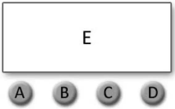
A. MENU
B. UP
C. DOWN
D. CONARM
E. DIGITAL DISPLAY WINDO
Display:
| MENU | To select the programming functions (press to unlock screen) |
| DOWN | To go backward in the selected functions |
| UP | To go forward in the selected functions |
| ENTER | To confirm the selected functions |
Set DMX Address:
- Press “MENU” to unlock screen, then select the “DMX Address” and press “ENTER”.
- Showing “Set DMX Address 001”, Press the “UP or DOWN” key to increase or decrease the DMX address value.
- Press “ENTER” to save and Exit, Press “Cancel” does not save and Exit.
| Level 1 | Level 2 | Description |
| DMX Address | 001-512 | Set DMX address |
| DMX Channel Mode | DMX_CH7 | 7 channels DMX mode |
| DMX_CH14 | 14 channels DMX mode | |
| DMX_CH42 | 42 channels DMX mode | |
| DMX_CH15 | 15 channels DMX mode | |
| DMX_CH43 | 43 channels DMX mode | |
| Dimmer Mode | DIM1 | Dimmer mode 1 |
| DIM2 | Dimmer mode 2 | |
| DIM3 | Dimmer mode 3 | |
| DIM4 | Dimmer mode 4 | |
| DIM5 | Dimmer mode 5 | |
|
Mode Selection | DMX512 | DMX mode |
| Auto1 | Auto run mode 1 | |
| Auto2 | Auto run mode 2 | |
| Auto3 | Auto run mode 3 | |
| Y motor | Tilt movement | |
| White | Beam dimmer | |
| W stroboscopic | Beam strobe | |
| Red | Back light red dimmer | |
| Green | Back light green dimmer | |
| Blue | Back light blue dimmer | |
| RGB stroboscopic | Back light strobe | |
| System Setting | Language | 语言/English |
| Bk_Light | OFF/ON | |
| Dmx512 | Clear/Keep | |
| W-DMX | Link/Unlink ( W-DMX version only ) | |
| System Info | RDM UID | RDM UID |
| Version | Software Version Number |
Specification
Strobe Panel LEDs
LED Type: 5050 0.5W RGB 3in1 LEDs
LED Count: 480
LED Colors: RGB
LED Segments: 8 (2 x 4)
Strobe Tube LEDs
LED Type: 3535 5W 6500K LEDs
LED Count: 144
LED Colors: Cool-White
LED Segments: 4
Movement
Resolution: 8-16 Bit
Tilt (Degrees): 185°
Control
Control Modes: 7CH / 14CH / 42CH / 15CH / 43CH
Display: Illuminated graphic LCD
Protocol: USITT DMX-512, RDM
RDM: Bidirectional communication
Wireless DMX: 2.4 GHz W-DMX™ (optional)
Cooling: Temperature controlled, overheating protection
Effects
Dimmer: 0-100% electronic
Shutter: electronic, max. 20 Hz
Internal Effects: LED Macro Ef
Connectors
Signal connection: Seetronic IP65 XLR 5-Pin or 3-Pin In/Out
Power Input: Seetronic PowerCON TRUE1 In/Out
Operating Conditions
Mains voltage: 100-240V AC / 50-60Hz
Power: 1000W
Maximum ambient temperature: -30°C / 86°F, 50°C / 122°F
Operating Position: any
Mounting Options
Hanging: Omega-Bracket
Safety wire attachment: foldout eyelets
Shipping
Single fixture: cardboard (inner and outer cartons)
Tourpack: 4-way Flight Case
Housing Colors
Standard colors: black
Dimensions
Length: 482 mm / 18.9 in
Width: 178 mm / 9.0 in
Height (head horizontal): 243 mm / 9.5 in
Weight
N.W: 10 kg
G.W: 12.5 kg


