![]()
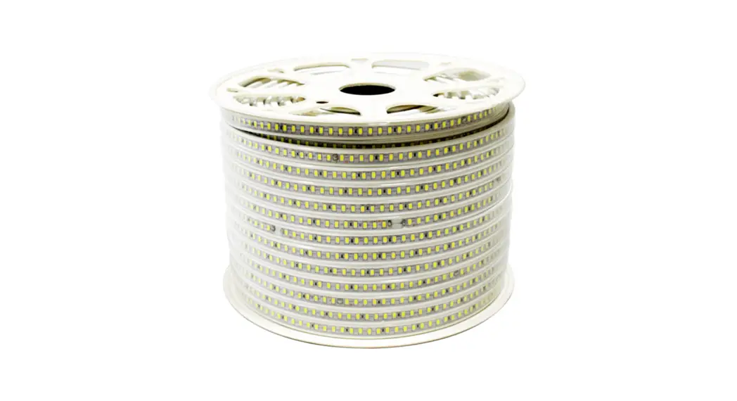
![]() Standard IP67 REACH25
Standard IP67 REACH25
The ![]() LED strip is suitable for installation in dry and wet interiors as well as outdoors.
LED strip is suitable for installation in dry and wet interiors as well as outdoors.![]() Risk of electric shock!
Risk of electric shock!
Be sure to have a professional electrician complete the installation. There is no warranty coverage for any lights installed without observing European safety directives.![]() Caution!
Caution!
Only connect the![]() LED strip to a suitable power supply (24 V DC).
LED strip to a suitable power supply (24 V DC).
Only operate when completely unrolled.
Connect ![]() LED strips in parallel.
LED strips in parallel.
Connect
LED strips in parallel.
Scope of delivery
1 x 25 meter
LED strip
4 x end cap
4 x feeder cap
1 x 150 mm connection cable
100 x holder
Technical data
| Power supply | 24 V power supply with constant output voltage |
| Power | 100 W |
| Current strength | 4.17 A |
| Beam angle | 120° |
| Quantity LED | 1500 |
| Length | maximum 25 meters per connection |
| Dimensions | 25000 x 12 x 6 mm |
| Bending diameter | 120 mm |
 | Compliant with the applicable european CE directives |
| Safety class 3 – low voltage protection | |
| not uv-resistent |
Please refer to the respective article on www.rutec.de for complete technical data!
Installation
![]() Risk of electric shock!
Risk of electric shock!
Switch off voltage prior to installation. Ensure that voltage cannot be accidentally switched on again.![]() Caution! On conducting surfaces, place an insulation layer between the LED strip and surface. Surfaces must be flat, free of dust, grease and dry.
Caution! On conducting surfaces, place an insulation layer between the LED strip and surface. Surfaces must be flat, free of dust, grease and dry.
- Prepare surface.
- Shorten the
 LED strip if necessary (Fig. 1).
 - Mount LED strip with help of included holder in a distance of ~25-30 cm without pressing onto electronic components.
- Connect LED strip to the power supply.
Shortening the LED strip
Risk of electric shock!
Always disconnect the mains plug before shortening.![]() LED strip can be separated in each case after six LEDs (100 mm) (Fig. 1).
LED strip can be separated in each case after six LEDs (100 mm) (Fig. 1).
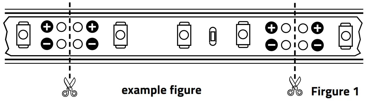 Separate the
 ![]() LED strip at the marked position.
LED strip at the marked position.
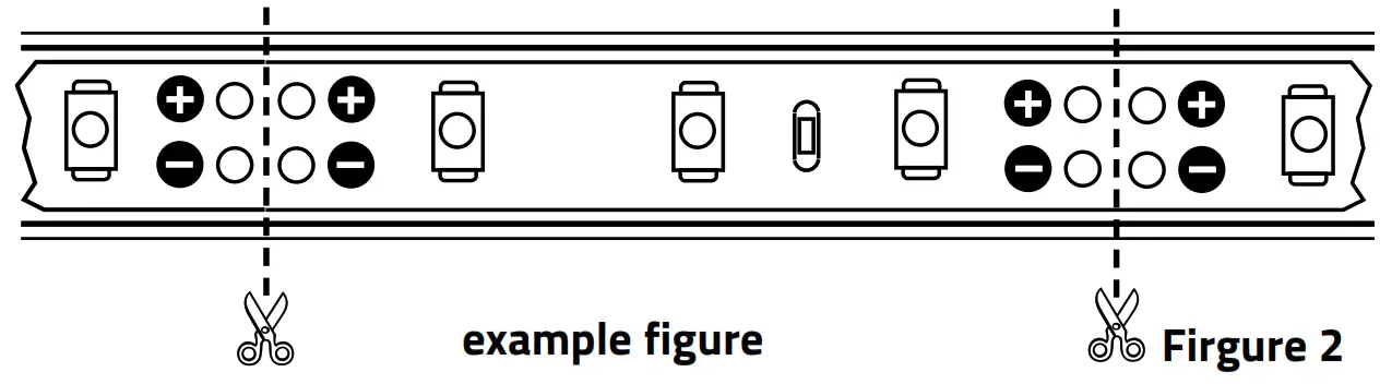
For a tightly assembled LED strip is a micro side cutter or an optional cutter required. Glue the end cap with neutral cross-linking silicone at the end of the separation point.![]() Caution!
Caution!
With soldered connections note that the soldering temperature is 260° C and the soldering duration a maximum of 10 seconds per soldering point. Only use neutral cross-linked silicon (never use silicon that includes vinegar!).
Connection:
- Fix a two-wired stranded connection cable with the help of lead-free solder to the soldering contacts of the separation point in compliance with the above-mentioned soldering temperature indication.
- Close open silicone tube ends with neutral cross-linking silicone.
Disposal Dispose of electrical and electronic equipment in an environmentally friendly manner. Please contact your local council for further information.
Standard IP67REACH25_BA_86550_10/2021
Carl-Zeiss-Str. 15 28857 Syke


