![]() 5671525 Shifters Line Locks
5671525 Shifters Line Locks
Instruction Manual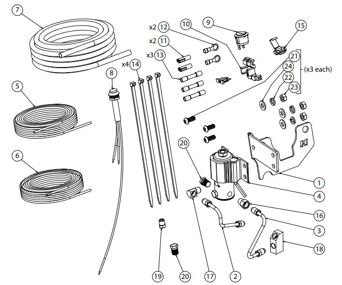
5671525 Shifters Line Locks
| ITM # | PART # | DESCRIPTION | QTY. |
| 1 | 1179524 | Bracket | 1 |
| 2 | 4460015 | Brake Line to Prop Valve | 1 |
| 3 | 4460016 | Brake Line to Y-Fitting | 1 |
| 4 | 97001789 | Solenoid Valve | 1 |
| 5 | 5100075 | 18 GA Wire | 15 |
| 6 | 5100082 | 18 GA Red Wire | 15 |
| 7 | 4001683 | Convoluted Split Sleeve | 15 |
| N/A | 5671525BA-01 | Hardware Package includes: | 1 |
| 8 | 2482001-40 | Lit Momentary Switch | 1 |
| 9 | 2482002 | On/Off Switch | 1 |
| 10 | 97001847 | Inline Fuse Holder w/ Fuse | 1 |
| 11 | 5000282 | 18 GA Terminal | 2 |
| 12 | 5000280 | Connector ¹⁄ıь” 18 GA Eyelet | 2 |
| 13 | 5000055-99 | 18 GA Red Splice | 3 |
| 14 | 5000254 | Cable Tie | 4 |
| 15 | 5000163-99 | 18 GA Tap Connector | 1 |
| N/A | 5671525BA-02 | Hardware Package includes: | 1 |
| 16 | 1400485 | ³⁄ıь x ¹⁄8 NPT Fitting | 1 |
| 17 | 1400487 | ³⁄ıь x ¹⁄8 NPT 90° Elbow Fitting | 1 |
| 18 | 1400480 | 90° ³⁄8″ 3 Way Flare Fitting | 1 |
| 19 | 1400489 | ³⁄8-16 Invtd. Flare Plug Fitting | 1 |
| 20 | 1400490 | ¹⁄8 NPT Plug Fitting | 2 |
| N/A | 5671525BA-03 | Hardware Package includes: | 1 |
| 21 | 3401556 | ¹⁄И-20 x ¹⁄8″ Screw | 3 |
| 22 | 3400131 | ¹⁄И” Split Lock Washer | 3 |
| 23 | 3400028 | ¹⁄И-20 Hex Nut | 3 |
| 24 | 3401598 | ¹⁄И” Flat Washer | 3 |
OVERVIEW:
CAUTION:
Carefully read and comprehend all instruc ons before beginning install. If you are inexperienced performing this type of install, we strongly recommend using a qualifi ed mechanic or shop to complete it.
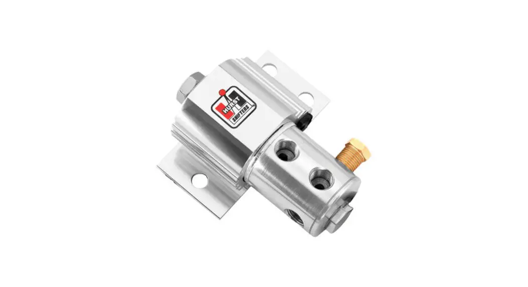
Congratula ons on the purchase of your new HURST Roll Control system, featuring advanced design quality stainless steel valve assembly for resistance to corrosion, greater durability, reliability and more precise positive action.
WARNINGS:
This system is designed primarily for high performance race cars to momentarily engage front brakes (max 60 seconds) while staging for a drag race. It wont safely func
on as a long term brake holding device.
It should be used only on specifi ed applica ons with a standard hydraulic braking system that is in a safe, operable condi on.
It should never be used as a temporary brake holding device in place of a parking brake or of a driver depressing the brake pedal.
We do NOT recommend installing system on vehicles equipped with an -lock or split diagonal brake systems.
INSTALLATION NOTES:
When working on brake system; maintain a clean working area, not allowing dirt or foreign matter to contaminate it which may allow improper operation and failure.
The Roll Control solenoid valve will not interfere with normal brake operation when properly installed in accordance with directions provided.
On any vehicle, rear brake lights must operate when brake system is under pressure. Therefore, a pressure operated switch must be installed if the Roll Control system defeats the purpose or function of factory rear brake light switch.
The Roll Control solenoid valve must be firmly mounted to prevent brake lines from flexing and causing failures. Mount it on fire wall, away from headers, exhaust pipes, steering and suspension components. Use a line fitting wrench on all line fittings while installing brake lines.
CAUTION: Using thread seal to excess can contaminate the solenoid valve or brake system. Use sparingly and do NOT apply it to starter thread of fittings.
After install, bleed all air out of system following vehicle manufacturers brake bleeding procedures.
CAUTION: Be sure to check all connections for leakage under pressure. There must be NO leakage.
Use a top quality heavy duty brake fluid that meets DOT 3 or DOT 4 specifications. Most domestic manufactures use five general types of brake systems.
SOLENOID VALVE:
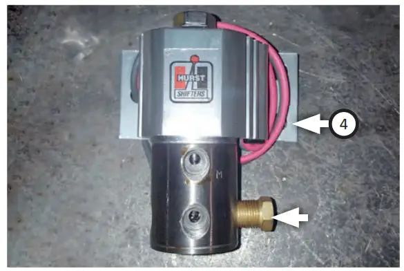
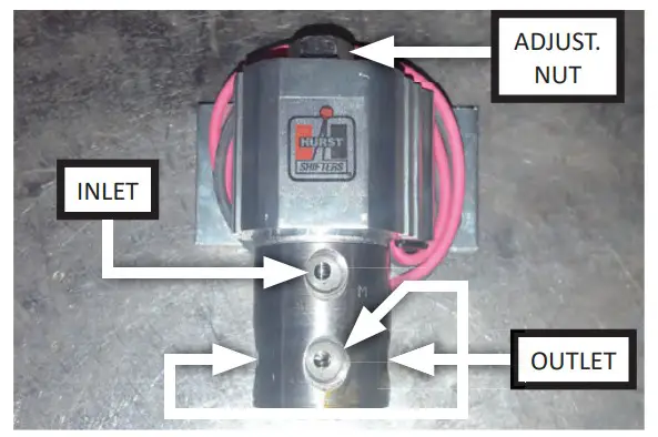 The solenoid valve features four holes to regulate pressure; the top hole is an inlet, the bottom three are outlets. On top of the valve is an adjustment nut for positioning unit properly.
BEGIN ASSEMBLY:
 Remove brass plug from valve solenoid (4).
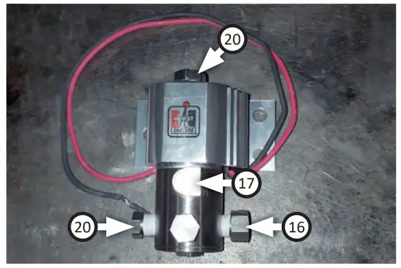
- Apply teflon tape to all pipe threads.

- Install (x2) plug fitting (20), fitting (16) and 90° fitting (17) as shown. Ensure fittings are tight to prevent leaks.

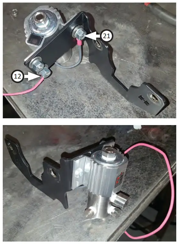
- Mount solenoid to mounting bracket with (x3 ea.) screws (21), fl at washers (24), split lock washers (22) and nuts (23). Ground solenoid to bracket (1) using eyelet (12).
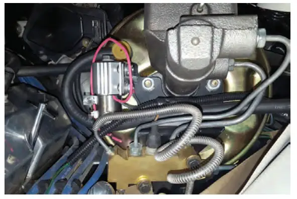
- Remove (x2) nuts that mount master cylinder to brake booster. Do NOT remove master cylinder.

- Mount solenoid assembly onto brake booster studs where (x2) nuts were removed.

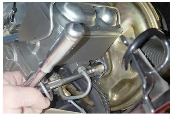
- Remove right front brake line from bottom of proportion valve and install inverted flare plug fitting (19).

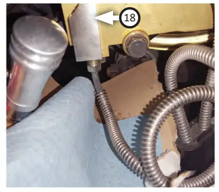
- Thread right front brake line into bottom of 3-way flare fitting (18).

- Remove left front brake line from proportion valve then insert it into upper hole of 3-way fitting.
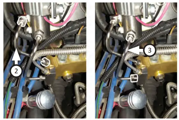
- Install brake line (2) to solenoid inlet and left front brake port on proportion valve. Install brake line (3) to solenoid outlet and center hole on 3-way fitting.
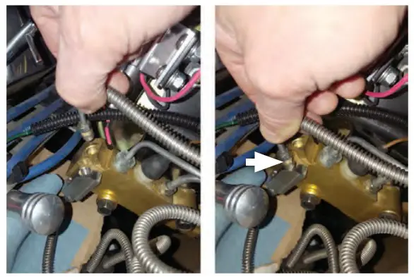
- Once all lines have been installed, go back and tighten all connections with a flare nut wrench. Brake lines must be as tight as possible to prevent leaks. You may use two wrenches for leverage.
- Perform factory recommended brake bleeding procedure.
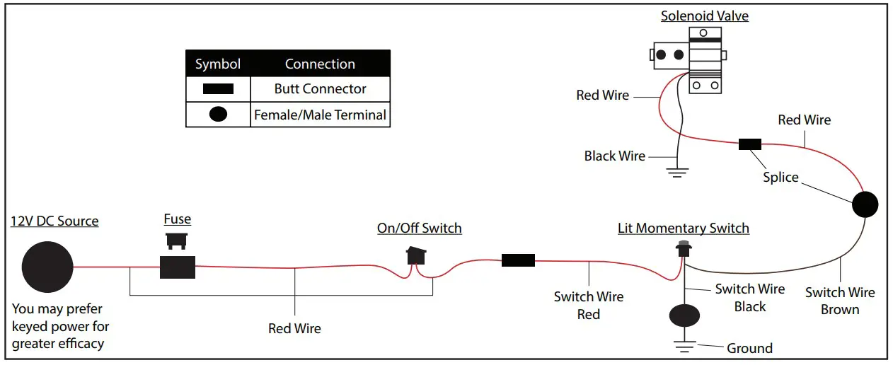
WIRING DIAGRAM:
 This Wiring Diagram illustrates how kit is connected together. Steps 13-21 show one way to install Roll Control kit.
You may install kit differently on your vehicle according to your preference or build, just as long as your wiring matches diagram below, avoids any tangles, avoids heated and/or moving parts and you have easy access to switches once complete.
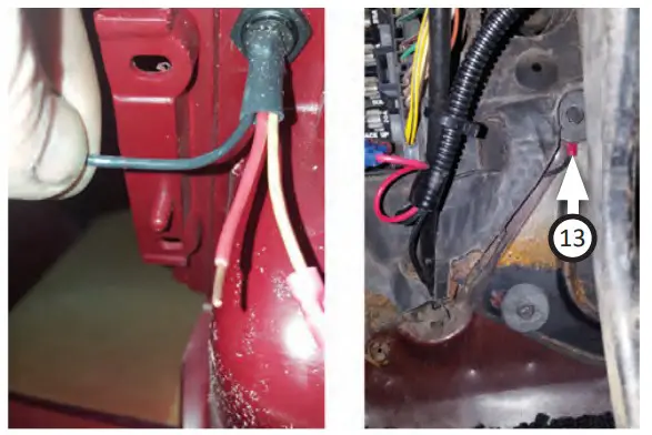
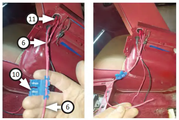
- Connect red wire (6) to power wire with red splice (13) and trim just enough red wire to reach from solenoid to vehicle interior.

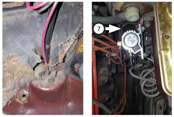
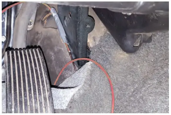
- Make a small hole in rubber boot at firewall then draw power wire through it to inside of vehicle. Cover power wire with split sleeve (7).

- To mount switches on center console, pull carpet back then draw power wire through to center console as shown.

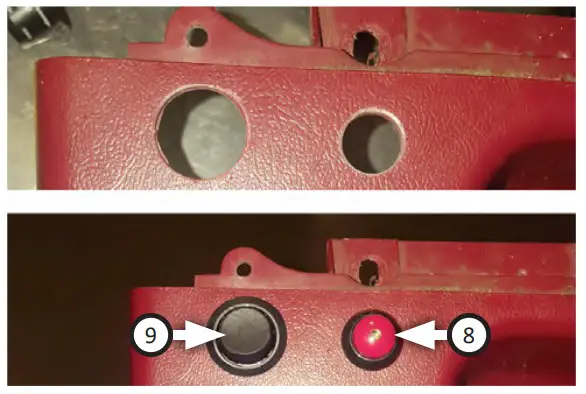
- Drill and mount On/Off switch (9) and lit momentary switch (8) to console as shown.
NOTE: This step is completed most efficiently using a step drill bit so you can check fitment at each “step” until hole is the correct size.
- Use splice (13) to connect solenoid power wire (that was routed through firewall to center console) to brown wire on lit momentary switch.

- Extend momentary switch black ground wire with splice (13), black wire (5) and eyelet (12). Ground this wire to chassis (this kit was grounded at firewall).

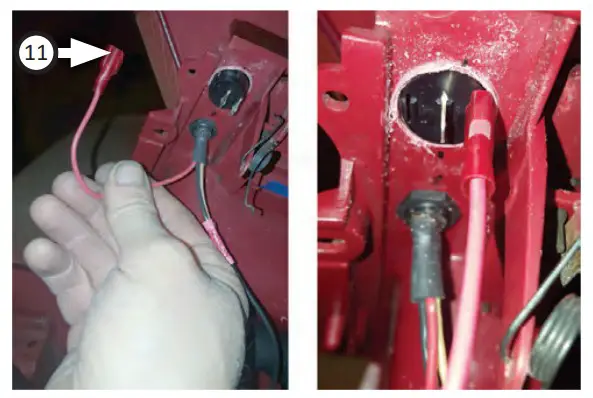
- Install terminal (11) to red wire (7) then plug it into on/off switch reaming post. Then use fuse holder (10) and more red wire (6) to reach power source.
- Install terminal (11) on momentary switch red wire then plug it into On/Off switch.

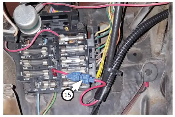
- Attach red wire to a power source using tap connector (15) if necessary.
OPERATION INSTRUCTIONS:
To actuate the Hurst Roll/Control system (BURNOUT):
- With Traction Control/ESP OFF, fully depress and hold brake pedal.
- Arm Hurst Roll Control system by depressing ON/ OFF (arm) switch to “ON” position (Lit Momentary Switch should illuminate).
Complete next steps within 60 seconds. - Hold momentary switch down and keep it held down until step 37 below.
- Release brake pedal. Front brakes will now be locked and rear wheels unlocked and free to spin.
- Automatic Vehicles- sharply step on gas pedal.
- Manual Vehicles- raise engine speed to a moderate level and smoothly but quickly release clutch.
- Rear wheels should now be spinning while vehicle is stationary if preceeding steps have been performed correctly.
- Modulate gas pedal to control amount of wheel spin.
- Release momentary switch and allow vehicle to “drive out” of burnout.
- Be prepared to ease off on gas pedal and press brake pedal if necessary.
- Disarm Hurst Roll Control system by depressing On/Off switch to “OFF” position (momentary switch should no longer be illuminated).
To actuate Hurst Roll/Control system (LAUNCH CONTROL — Automatic Vehicles Only): - With vehicle staged fully, depress and hold brake pedal.
- Arm Hurst Roll Control system by depressing On/ Off (arm) switch to “ON” position (momentary switch should illuminate).
- Hold momentary switch down and keep it held down until step 45 below.
- Release brake pedal. The front brakes will now be locked and rear wheels un-locked, free to be loaded.
- Slowly and smoothly step on gas pedal to load torque converter and drivetrain just prior to wheel spin (this step may take some practice).
- GO! Release momentary switch and modulate gas pedal as light turns green/flag drops/etc. to hard launch vehicle forward.
- Be prepared to ease off on gas pedal and press brake pedal if necessary.
- Disarm Hurst Roll Control system by depressing On/Off to “OFF” position (momentary switch should no longer be illuminated).
 Remove brass plug from valve solenoid (4).
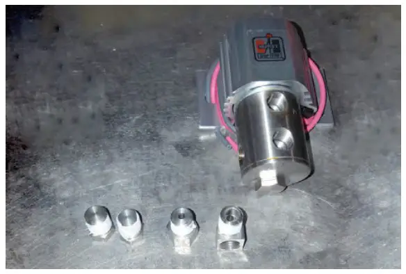

 This Wiring Diagram illustrates how kit is connected together. Steps 13-21 show one way to install Roll Control kit.
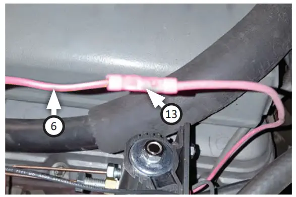

![]() Congratulations, the installation of your Hurst Roll Control is now complete!
Congratulations, the installation of your Hurst Roll Control is now complete!
5671525
Rev 05/02/22
www.hurst-shifters.com
Technical Support (866) 464-6553


