![]()
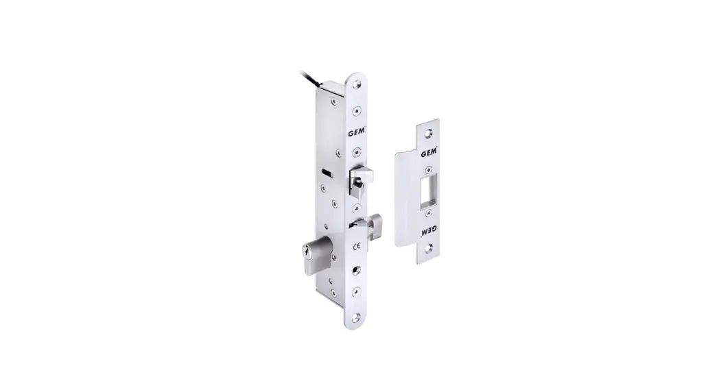
ML-605M Series Electro-Mechanical Lock
Installation Instruction
Specification
- Operating Voltage: 12~24VDC/AC ±10%
- Current Draw: 250mA/12VDC; 150mA/24VDC
- Operating Temperature: 14°F to 120°F (-10°C~+49°C)
- Humidity: 0~85% non-condensing
- Version Changeable: Fail-safe or Fail-secure
- Lock bolt sensor switch output: SPDT, 3A/125VAC
- Latch Throw:16mm
- Solenoid testing: Tested to 250,000 cycles
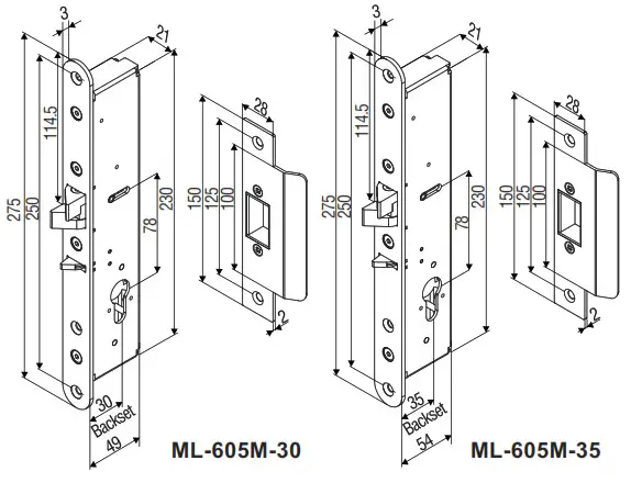
- Backset:
ML-605M-30: 30mm
ML-605M-35: 35mm
Packing Contents
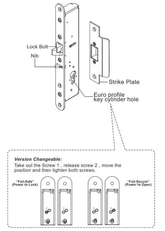
 Caution: Do not completely remove screw 2 (as marked in the figure) as the interior solenoid might fall off.
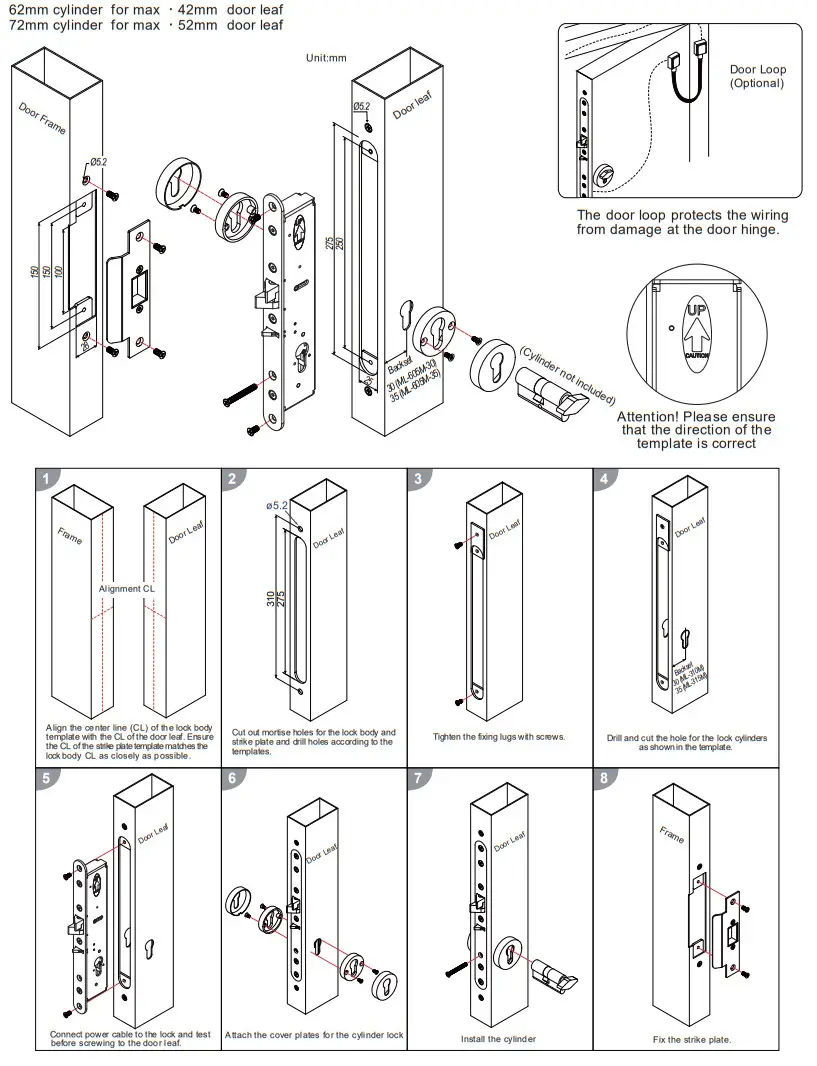
Dimension
Stud Bolt Position
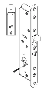
For fail-secure mode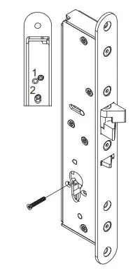
Installation Instructions
Wiring Diagram
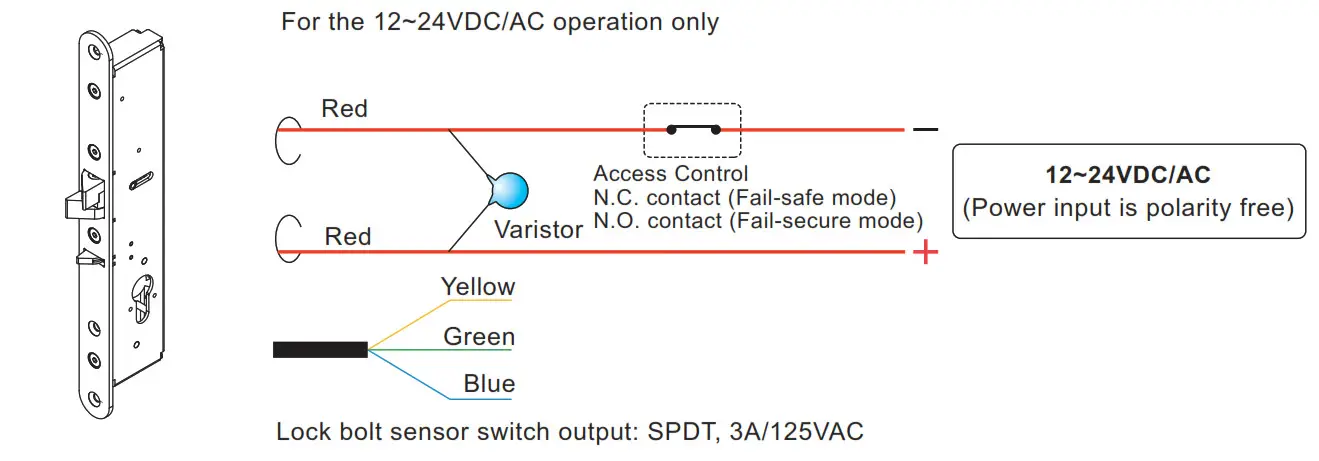
NOTE: The varistor (or diode) must be connected across the terminals as shown above. This protects the electromechanical lock from spikes and surges.
Butt Splice (IDC) Connector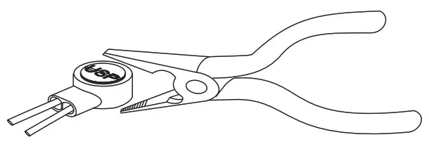 Using crimper or pliers and pressing the header of connector down to even position.


