MW SDR-240 Series 240W Single Output Industrial DIN RAIL with PFC Function Owner’s Manual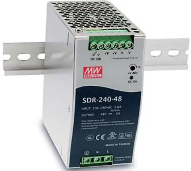
Features
- High efficiency 94% and low power dissipation
- 150% peak load capability
- Built-in active PFC function, PF>0.93
- Protections: Short circuit / Overload / Over voltage / Over temperature
- Cooling by free air convection • Can be installed on DIN rail TS-35/7.5 or 15
- UL 508 (industrial control equipment) approved
- BS EN/EN 61000-6-2(BS EN/EN 50082-2) industrial immunity level
- Built-in DC OK relay contact
- 100`)/0 full load burn-in test
GTIN CODE
MW Search: https://www.meanwell.com/serviceGTlN.aspx
SPECIFICATION
| MODEL | SDR-240-24 | SDR-240-48 | |
| OUTPUT | DC VOLTAGE | 24V | 48V |
| RATED CURRENT | 10A | 5A | |
| CURRENT RANGE | 0 ~ 10A | 0 ~ 5A | |
| RATED POWER | 240W | 240W | |
| PEAK CURRENT | 15A | 7.5A | |
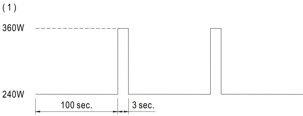
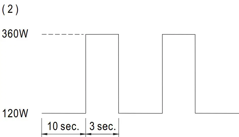
| PEAK POWER Note.6 | 360W (3sec.) | ||
| RIPPLE & NOISE (max.) Note.2 | 50mVp-p | 50mVp-p | |
| VOLTAGE ADJ. RANGE | 24 ~ 28V | 48 ~ 55V | |
| VOLTAGE TOLERANCE Note.3 | ±1.0% | ±1.0% | |
| LINE REGULATION | ±0.5% | ±0.5% | |
| LOAD REGULATION | ±1.0% | ±1.0% | |
| SETUP, RISE TIME | 650ms, 60ms/230VAC 1300ms, 60ms/115VAC at full load | ||
| HOLD UP TIME (Typ.) | 20ms/230VAC 20ms/115VAC at full load | ||
| INPUT | VOLTAGE RANGE | 88 ~ 264VAC 124 ~ 370VDC | |
| FREQUENCY RANGE | 47 ~ 63Hz | ||
| POWER FACTOR (Typ.) | 0.94/230VAC 0.99/115VAC at full load | ||
| EFFICIENCY (Typ.) Note.8 | 94% | ||
| AC CURRENT (Typ.) | 2.6A/115VAC 1.3A/230VAC | ||
| INRUSH CURRENT (Typ.) | 33A/115VAC 55A/230VAC | ||
| LEAKAGE CURRENT | <1mA / 240VAC | ||
| PROTECTION | OVERLOAD | Normally works within 110 ~ 150% rated output power for more than 3 seconds and then shut down o/p voltage with auto-recovery | |
| >150% rated power, constant current limiting with auto-recovery within 2 seconds and may cause to shut down if over 2 seconds | |||
| OVER VOLTAGE | 29 ~ 33V | 56 ~ 65V | |
| Protection type : Shut down o/p voltage with auto-recovery | |||
| OVER TEMPERATURE | 95℃±5℃ (TSW : detect on heatsink of power switch) | ||
| Protection type : Shut down o/p voltage, recovers automatically after temperature goes down | |||
| FUNCTION | DC OK REALY CONTACT RATINGS (max.) | 60Vdc/0.3A, 30Vdc/1A, 30Vac/0.5A resistive load | |
| ENVIRONMENT | WORKING TEMP. Note.5 | -25 ~ +70℃ (Refer to “Derating Curve”) | |
| WORKING HUMIDITY | 20 ~ 95% RH non-condensing | ||
| STORAGE TEMP., HUMIDITY | -40 ~ +85℃, 10 ~ 95% RH | ||
| TEMP. COEFFICIENT | ±0.03%/℃ (0 ~ 50℃) | ||
| VIBRATION | Component:10 ~ 500Hz, 2G 10min./1cycle, 60min. each along X, Y, Z axes; Mounting: Compliance to IEC60068-2-6 | ||
| SAFETY & EMC(Note 4) | SAFETY STANDARDS | UL508, TUV BS EN/EN62368-1, AS/NZS 62368.1, EAC TP TC 004 approved;(meet BS EN/EN60204-1) | |
| WITHSTAND VOLTAGE | I/P-O/P:3KVAC I/P-FG:2KVAC O/P-FG:0.5KVAC O/P-DC OK:0.5KVAC | ||
| ISOLATION RESISTANCE | I/P-O/P, I/P-FG, O/P-FG:>100M Ohms / 500VDC / 25℃/ 70% RH | ||
| EMC EMISSION | Compliance to BS EN/EN55032 (CISPR32), BS EN/EN61204-3 Class B, BS EN/EN61000-3-2,-3, EAC TP TC 020 | ||
| EMC IMMUNITY | Compliance to BS EN/EN61000-4-2,3,4,5,6,8,11, BS EN/EN55035, BS EN/EN61000-6-2 (BS EN/EN50082-2),BS EN/EN61204-3, heavy industry level, EAC TP TC 020, SEMI F47 approved | ||
| OTHERS | MTBF | 1160.3K hrs min. Telcordia SR-332 (Bellcore) ; 169.3K hrs min. MIL-HDBK-217F (25℃) | |
| DIMENSION | 63*125.2*113.5mm (W*H*D) | ||
| PACKING | 1.03Kg; 12pcs/13.4Kg/1.22CUFT | ||
| NOTE |
※ Product Liability Disclaimer:For detailed information, please refer to https://www.meanwell.com/serviceDisclaimer.aspx | ||
Mechanical Specification
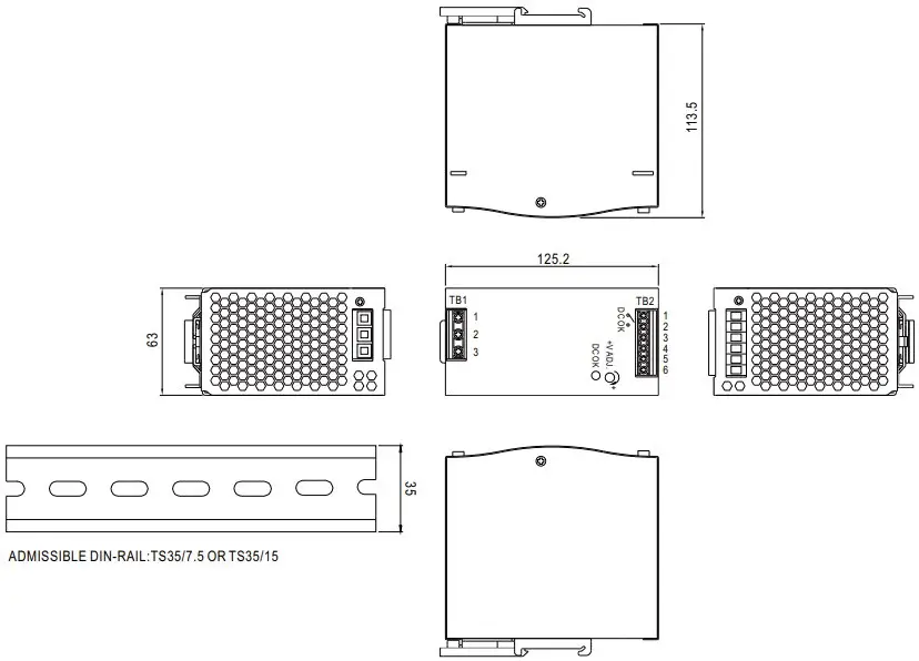
Terminal Pin No. Assignment (TB1)
| Pin No. | Assignment |
| 1 | FG |
| 2 | AC/N |
| 3 | AC/L |
Terminal Pin No. Assignment (TB2)
| Pin No. | Assignment |
| 1,2 | Relay Contact |
| 3,4 | DC OUTPUT +V |
| 5,6 | DC OUTPUT -V |
Block Diagram
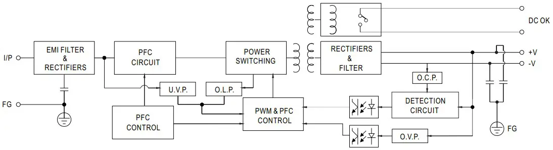
| Contact Close | PSU turns on / DC OK. |
| Contact Open | PSU turns off / DC Fail. |
| Contact Ratings (max.) | 30V/1A resistive load. |
Peak Loading
Derating Curve
AMBIENT TEMPERATURE ( )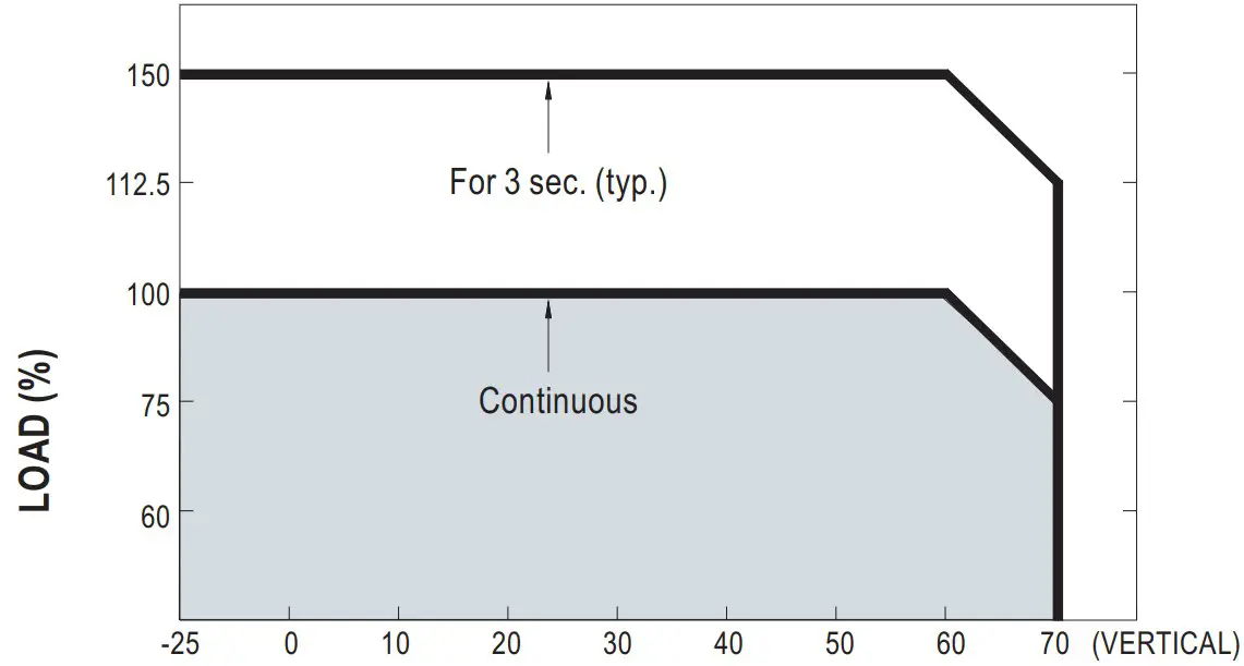
Output derating VS input voltage
INPUT VOLTAGE (V) 60Hz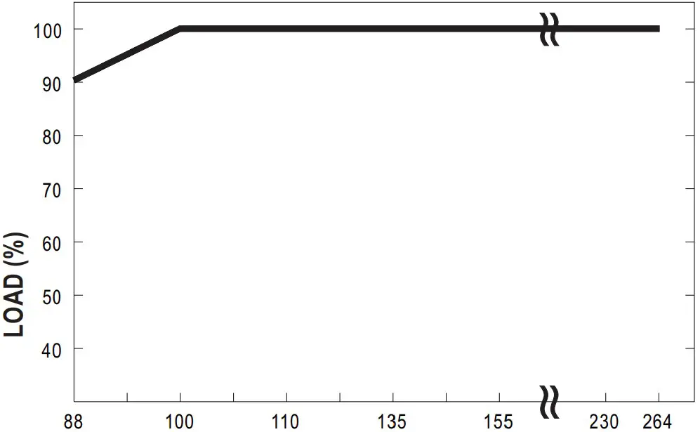
File Name: SDR-240-SPEC 2022-09-20
User’s Manual
Symbols![]()