
BILLION BEC B14-15 OEM-Integrator Installation Guide
General description
BEC B41-25 is an advanced mule-band CA712 LTE PCIe Mini card product tot embedded LTE module market. II supports standard PCIe USB Interface and can be early integrated bb laptop. se•top box and real lame industry devices to provide instant advanced 4G broadband carmunicabon capability.
Quote Criterion
Meet 3GPP LTE-A Release12. 115133.0 Standard. in PCI Express
Power Characteristic
Input Voltage Range
Rated operating voltage 3.8Vdc to 5.5Vdc input DC voltage MAI PO-E).
Rated Power
Average 2.7 W@SV. Peak 4W@SV.
Environmental Requirement
Operating Temperature
-30 to 55C
Storage Temperature
-40 to WC
Mechanical Requirement
Dimension
The nominal external dimensions of the LTE module are 51mm ‘ 42mm • 6mm
Weight
Weight are approx. 20g.
Vibration Test Requirement
Non-operating. with packing) Reference to !EC publ. 68-2-6
| Test conditions | Acceptance Criteria | |
| Frequency | 10~55Hz | |
| Sweep | 2hours, For each axis | Nominal functional test |
| (X, Y, Z) | should be satisfied after | |
| Acceleration | 0.6G 1.5G | the |
| (5~50Hz, peak-peak) | test | |
| Displacement | 0.35 mm(5~50Hz) | |
Physical Interface
Antenna Connectors
BEC B41-15 is mounted with four antenna connectors for external antenna connection: a main antenna connector, an aux antenna connector, and 2 Rx-diversity function is enabled by default. The impedance of the antenna connectors is 50Ω.
The connector type is IPEX-1.
Hardware Connector
52-Pin Mini PCI-E card interface
Network Connector
USB3.0 & USB2.0
Radio Spec
Duplex mode
TDD
Frequency
LTE BAND 41
Bandwidth
5MHz 10MHz, 15MHz, 20MHz
Conducted RF Output Power
| Frequency Band | Max. | Min. |
| B41 | 17±2dBm | <-40dBm |
DL MIMO and CA
Support 8*4 MIMO (1CC), 4*4 MIMO (2CC), 2*2 MIMO (3CC & 4CC)
Pin Assignment
| N o | Standard PCIE signal | Signal Description | Pin Definitions | Signal Direction | Support Signal Level | Note |
| 1 | WAKE# | AP2CP_WAKE | AP2CP_WAKE(G PD2_0) | Input | 1.8V | |
| 2 | 3.3Vaux | VBATT | VCC_PCIE | Input | 3.8~5.5V | |
| 3 | COEX1 | CP2AP_WAKE | CP2AP_WAKE(G PD2_1) | Output | 1.8V | |
| 4 | GND | GND | GND | GND | GND | |
| 5 | COEX2 | GPIO | GPD2_2 | In/Out | 1.8V | |
| 6 | 1.5V | GPIO | GPD2_9 | In/Out | 1.8V | |
| 7 | CLKREQ# | GPIO | GPD2_3 | In/Out | 1.8V | |
| 8 | UIM_PWR | VSIM_1V8_3V0 | SIM_PWR | Output | 1.8/3.0V | |
| 9 | GND | GND | GND | GND | GND | |
| 10 | UIM_DATA | SIM_DATA | SIM_DATA | In/Out | SIM_DATA | |
| 11 | REFCLK- | UART_RXD | UART_RXD | Input | 1.8V | |
| 12 | UIM_CLK | SIM_CLK | SIM_CLK | Input | SIM_CLK | |
| 13 | REFCLK+ | UART_TXD | UART_TXD | Output | 1.8V | |
| 14 | UIM_RESET | SIM_RST | SIM_RST | Input | SIM_RST | |
| 15 | GND | GND | GND | GND | GND | |
| 16 | UIM_VPP | GPIO | GPD2_10 | In/Out | 1.8V | |
| 17 | Reserved (UIM_C8) | NC | NC | NC | NC | |
| 18 | GND | GND | GND | GND | GND | |
| 19 | Reserved (UIM_C4) | NC | NC | NC | NC | |
| 20 | W_DISABLE# | GPIO | W_DISABLE(GPD 2_11) | Input | 1.8V | |
| 21 | GND | GND | GND | GND | GND | |
| 22 | PERST# | MB2PCIE_RST_ N | PE_RST | Input | 3.8~5.5V | Power on Reset |
| 23 | PERn0 | USB3.0 | USB3.0_TX- | Output | USB3.0_TX- | |
| 24 | 3.3Vaux | VBATT | VCC_PCIE | Input | 3.8~5.5V | |
| 25 | PERp0 | USB3.0 | USB3.0_TX+ | Output | USB3.0_TX+ | |
| 26 | GND | GND | GND | GND | GND | |
| 27 | GND | GND | GND | GND | GND | |
| 28 | 1.5V | NC | NC | NC | NC | |
| 29 | GND | GND | GND | GND | GND | |
| 30 | SMB_CLK | NC | NC | NC | NC | |
| 31 | PETn0 | USB3.0 | USB3.0_RX- | Input | USB3.0_RX- | |
| 32 | SMB_DATA | NC | NC | NC | NC | |
| 33 | PETp0 | USB3.0 | USB3.0_RX+ | Input | USB3.0_RX+ | |
| 34 | GND | GND | GND | GND | GND | |
| 35 | GND | GND | GND | GND | GND | |
| 36 | USB_D- | USB_D- | USB_D- | I/O | USB_D- | |
| 37 | GND | GND | GND | GND | GND | |
| 38 | USB_D+ | USB_D+ | USB_D+ | I/O | USB_D+ | |
| 39 | 3.3Vaux | VBATT | VCC_PCIE | Input | 3.8~5.5V | |
| 40 | GND | GND | GND | GND | GND |
| 41 | 3.3Vaux | VBATT | VCC_PCIE | Input | 3.8~5.5V | |
| 42 | LED_WWAN# | NC | NC | NC | NC | |
| 43 | GND | GND | GND | GND | GND | |
| 44 | LED_WLAN# | NC | NC | NC | NC | |
| 45 | Reserved | NC | NC | NC | NC | |
| 46 | LED_WPAN# | NC | NC | NC | NC | |
| 47 | Reserved | NC | NC | NC | NC | |
| 48 | 1.5V | NC | NC | NC | NC | |
| 49 | Reserved | GPIO | Config Reset (GPD2_4) | Input | 1.8V | Soft Reset |
| 50 | GND | GND | GND | GND | GND | |
| 51 | Reserved | GPIO | GPD2_5 | In/Out | 1.8V | |
| 52 | 3.3Vaux | VBATT | VCC_PCIE | Input | 3.8~5.5V |
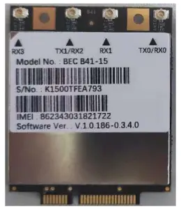
Photograph of the Product
Rating Label Drawing
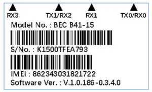
FCC ID: QI3BEC-B41-15
Professional installation instruction
- Installation personal
This product is designed for specific application and needs to be installed by a Qualified personal who has RF and related rule knowledge. The general user shall not attempt to install or change the setting. - Installation location
The product shall be installed at a location where the radiating antenna can be kept 20cm from nearby person in normal operation condition to meet regulatory RF exposure requirement. - External antenna
Use only the antennas which have been approved by the applicant. The non-approved antenna(s) may produce unwanted spurious or excessive RF transmitting power which may lead to the violation of FCC limit and is prohibited. - Installation procedure
Please refer to user’s manual for the detail. - Warning
Please carefully select the installation position and make sure that the final output power does not exceed the limit set force in relevant rules. The violation of the rule could lead to serious federal penalty.
Federal Communication Commission Interference Statement
This device complies with Part 15 of the FCC Rules. Operation is subject to the following two conditions: (1) This device may not cause harmful interference, and (2) this device must accept any interference received, including interference that may cause undesired operation.
This equipment has been tested and found to comply with the limits for a Class B digital device, pursuant to Part 15 of the FCC Rules. These limits are designed to provide reasonable protection against harmful interference in a residential installation. This equipment generates, uses and can radiate radio frequency energy and, if not installed and used in accordance with the instructions, may cause harmful interference to radio communications. However, there is no guarantee that interference will not occur in a particular installation. If this equipment does cause harmful interference to radio or television reception, which can be determined by turning the equipment off and on, the user is encouraged to try to correct the interference by one of the following measures
- Reorient or relocate the receiving
- Increase the separation between the equipment and
- Connect the equipment into an outlet on a circuit different from that to which the receiver is connected.
- Consult the dealer or an experienced radio/TV technician for
FCC Caution: Any changes or modifications not expressly approved by the party responsible for compliance could void the user’s authority to operate this equipment.
This transmitter must not be co-located or operating in conjunction with any other antenna or transmitter
Radiation Exposure Statement:
This equipment complies with FCC radiation exposure limits set forth for an uncontrolled environment. This equipment should be installed and operated with minimum distance 20cm between the radiator & your body
This module is intended for OEM integrators only. Per FCC KDB 996369 D03 OEM Manual V01 guidance, the following conditions must be strictly followed when using this certified module:
KDB 996369 D03 OEM Manual V01 rule sections:
- List of applicable FCC rules
This module has been tested for compliance to FCC Part 27. - Summarize the specific operational use conditions
The module is tested for standalone mobile RF exposure use condition. Any other usage conditions such as co-location with other transmitter(s) or being used in a portable condition will need a separate reassessment through a class II permissive change application or new certification - Limited module procedures
Not applicable - Trace antenna designs
N/A - RF exposure considerations
This equipment complies with FCC mobile radiation exposure limits set forth for an uncontrolled environment. This equipment should be installed and operated with a minimum distance of 20cm between the radiator & your body. If the module is installed in a portable host, a separate SAR evaluation is required to confirm compliance with relevant FCC portable RF exposure rules. - Antennas
The following antennas have been certified for use with this module; antennas of the same type with equal or lower gain may also be used with this module. The antenna must be installed such that 20 cm can be maintained between the antenna and users.Antenna Type Dipole PCB Antenna connector SMA ipex(MHF)
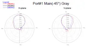
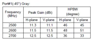
Antenna 1. (PCB antenna)
Port1.
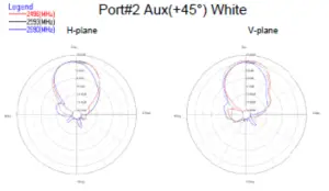
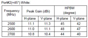
Port 2
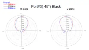
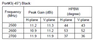
Port 3
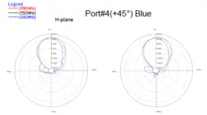
Port 4

Antenna 2. (Dipole antenna)
- Label and compliance information
The final end product must be labeled in a visible area with the following: “Contains FCC ID: QI3BEC-B41-15”. The grantee’s FCC ID can be used only when all FCC compliance requirements are met - Information on test modes and additional testing requirements
This transmitter is tested in a standalone mobile RF exposure condition and any co-located or simultaneous transmission with other transmitter(s) or portable use will require a separate class II permissive change re-evaluation or new certification - Additional testing, Part 15 Subpart B disclaimer
This transmitter module is tested as a subsystem and its certification does not cover the FCC Part 15 Subpart B (unintentional radiator) rule requirement applicable to the final host. The final host will still need to be reassessed for compliance to this portion of rule requirements if applicable.
As long as all conditions above are met, further transmitter test will not be required. However, the OEM integrator is still responsible for testing their end-product for any additional compliance requirements required with this module installed
IMPORTANT NOTE: In the event that these conditions can not be met (for example certain laptop configurations or co-location with another transmitter), then the FCC authorization is no longer considered valid and the FCC ID can not be used on the final product. In these circumstances, the OEM integrator will be responsible for re-evaluating the end product (including the transmitter) and obtaining a separate FCC authorization.
Manual Information To the End User
The OEM integrator has to be aware not to provide information to the end user regarding how to install or remove this RF module in the user’s manual of the end product which integrates this module. The end user manual shall include all required regulatory information/warning as show in this manual
OEM/Host manufacturer responsibilities
OEM/Host manufacturers are ultimately responsible for the compliance of the Host and Module. The final product must be reassessed against all the essential requirements of the FCC rule such as FCC Part 15 Subpart B before it can be placed on the US market. This includes reassessing the transmitter module for compliance with the Radio and EMF essential requirements of the FCC rules. This module must not be incorporated into any other device or system without retesting for compliance as multi-radio and combined equipment.
Our aim is to provide customers with timely and comprehensive service. For any assistance, please contact our company headquarters:
Billion Electric Co., Ltd.
8F, No. 192, Sec. 2, Zhongxign Rd., Xindian Dist., New Taipei City 23146, Taiwan Tel.:+886-2-29145665
Email: [email protected]
Or our local office. For more information, please visit: http://www.billion.com/page/contact/index.aspx


