![]() Installation Sheet
Installation Sheet
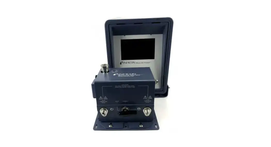
Micro GC Fusion® External Sample Conditioner
Introduction
Micro GC Fusion can be damaged by high pressure samples, especially those containing contaminants, such as condensing aerosols. The external sample conditioner (PN 952-004-G1) maintains the sample at > 50°C (122°F) and reduces the sample pressure from up to 5516 kPa (800 psi) down to approximately 0-172 kPa (0-25 psi) prior to the sample being introduced to Micro GC Fusion. This minimizes the introduction of contaminants and aerosols onto Micro GC Fusion.
The external sample conditioner can be installed on the front of a 2-module Micro GC Fusion and transported into the field for direct analysis.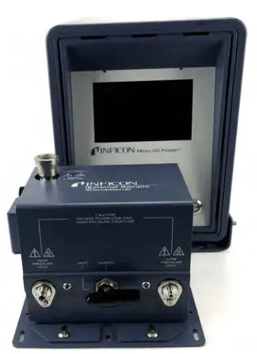
![]() CAUTION
CAUTION
Micro GC Fusion is intended for gas sampling only. Liquid injections will damage the instrument.![]() WARNING
WARNING
Gas pressure on the external sample conditioner vent may be up to 5516 kPa (800 psi). Extreme caution must be taken when venting the high pressure sample to avoid personal injury.![]() WARNING
WARNING
The external sample conditioner is rated for 5516 kPa (800 psi) input sample pressure.![]() WARNING
WARNING
Do not open the instrument case. There are no user-serviceable components within the instrument case.
Dangerous voltages may be present whenever power is present. Refer all maintenance to qualified personnel.![]() CAUTION
CAUTION
Do not use the product in a manner not specified by the manufacturer. If the product is used in a manner not specified by the manufacturer, the protection provided by the equipment may be impaired.![]() CAUTION
CAUTION
Use caution when mounting the external sample conditioner to a fixed position. Ensure there is enough room to disconnect the power cord when needed.![]() WARNING
WARNING
When working with chemicals, follow PPE guidelines listed in chemical safety data sheets (SDS).
Specifications
| ESC sample inlet connection | 1/4 in. Swagelok® female quick connect |
| Sample output temp to Micro GC Fusion | >50°C (122°F) |
| Maximum sample pressure | 5516 kPa (800 psi) |
| Minimum sample pressure | 14 kPa (2 psi) |
| Sample output pressure to Micro GC Fusion | Sample output pressure to Micro GC Fusion 0-172 kPa (0-25 psi) |
| High pressure venting connector | 1/8 in. Swagelok |
| Low pressure venting connector | 1/16 in. Swagelok |
| Filter | 7 µm |
| Power input | 85 to 264 V (ac), 47 to 63 Hz |
| Power output | 24 V (dc), 6.67A, 160 Watts maximum |
| Operating temperature | 0°C to 50°C (32°F to 122°F) ambient |
| Storage temperature | -20°C to 60°C (-4°F to 140°F) ambient |
| Relative humidity | 5 to 95% (non-condensing) |
| Altitude | 2,000 m (6,562 ft.) |
| Pollution degree | 2 per EN 61010 |
| Installation (overvoltage) | Category II per IEC 60664 |
| Cleaning | Use a mild, non-abrasive cleaner or detergent. Ensure the cleaner does not enter the unit. |
NOTE: The Micro GC Fusion external sample conditioner is designed for indoor use only.
Support
For support and technical assistance, please contact INFICON, 2 Technology Place, East Syracuse, NY 13057-9714.
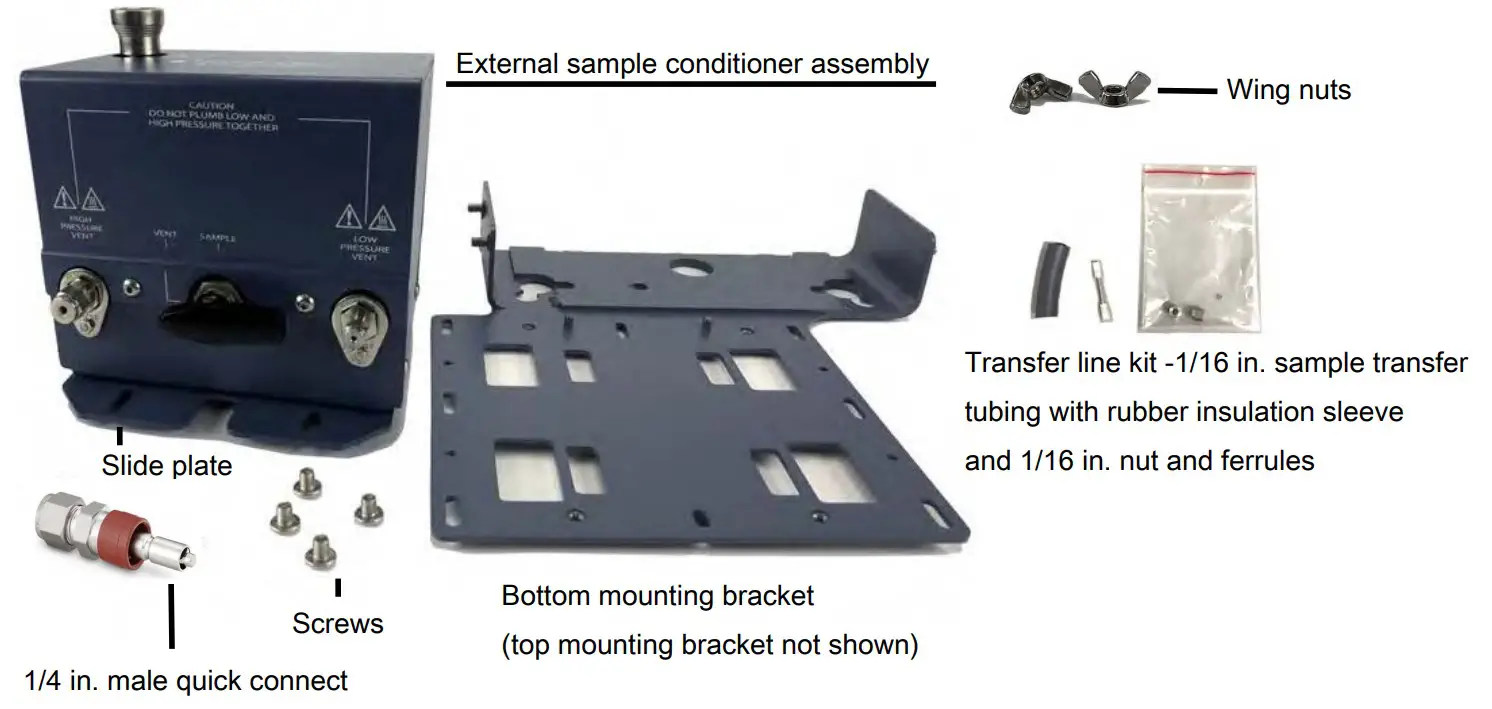
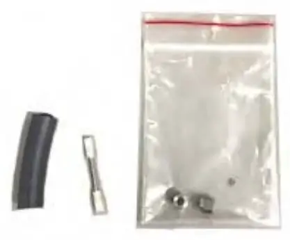
External Sample Conditioner Accessory Kit
| Description | Quantity |
| External sample conditioner assembly | 1 |
| Slide plate | 1 |
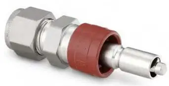
| 1/4 in. male quick connect (PN 059-0808S) | 1 |
| Screws | 4 |
| Bottom mounting bracket | 1 |
| Top mounting bracket (not shown) | 1 |
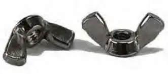
| Wing nuts (PN 144-374S) | 4 |
| Transfer line kit, includes 1/16 in. sample transfer tubing with rubber insulation sleeve and 1/16 in. nut and ferrules (PN 952-018-G1S) | 1 |
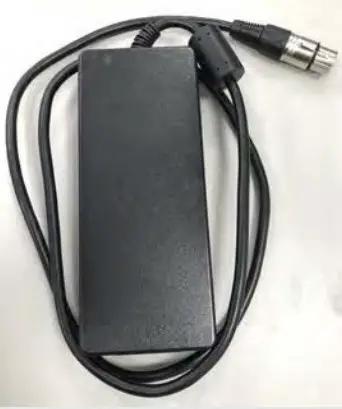
| Power supply (not shown, PN 033-0074S) | 1 |
List of Required Tools
The following tools are user supplied:
- one 7/16 in. open-ended wrench for 1/8 in. connections
- one 5/16 in. open-ended wrench for 1/16 in. connections
- 2.5 mm hex driver
- 3.0 mm hex driver
- 1 in. open-ended wrench for filter replacement
![]() CAUTION
CAUTION
Use caution when mounting the external sample conditioner to a fixed position. Ensure there is enough room to disconnect the power cord when needed.
The external sample conditioner can be installed on the 2-module Micro GC Fusion. The external sample conditioner is factory preassembled, and can be easily mounted onto Micro GC Fusion during instrument installation.
- Verify that the contents of the accessory kit are correct.
- Remove all of the parts from the packaging.
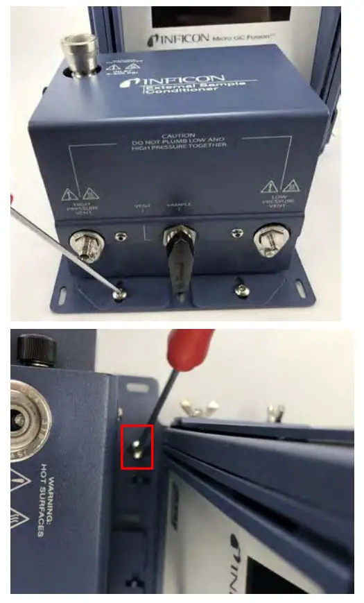
- Attach the external sample conditioner slide plate to the bottom of the device using a 2.5 mm hex driver.
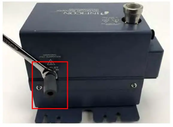
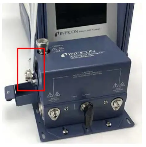
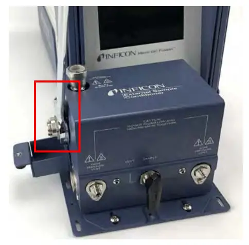
- Attach the 1/16 in. sample transfer line with the rubber insulation sleeve onto the external sample conditioner using a 5/16 in. openended wrench.
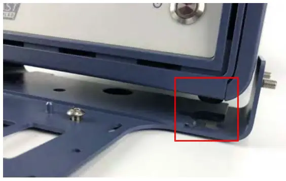
- Slide the bottom mounting bracket underneath Micro GC Fusion and align the feet with the dedicated holes.
- Slide the top bracket over Micro GC Fusion and the threads from the bottom bracket.
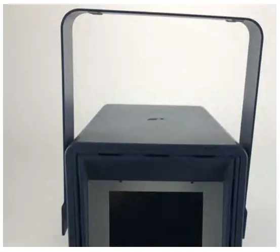
- Align the screws on both sides of the chassis.
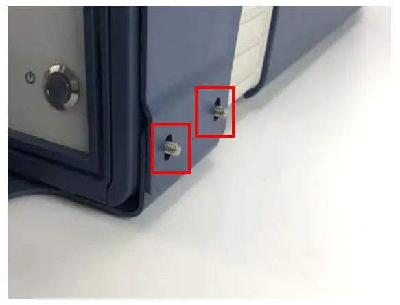
- Place the wing nuts on the bottom bracket threads and hand-tighten. Ensure that the top bracket is pressed downward and is tightly secured to Micro GC Fusion.
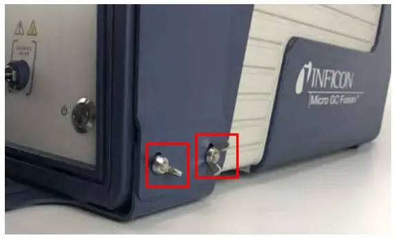
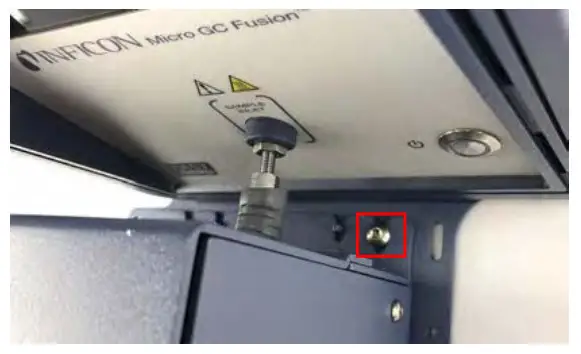
- Using a 3 mm hex driver, slightly thread the M4 screws into the holes on the bottom bracket, near the chassis of Micro GC Fusion.
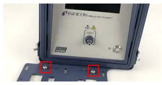
 Allow enough space for the external sample conditioner slide plate to fit under the screw head.
 - Place the external sample conditioner, with the slide plate and the sample transfer line, onto the bottom bracket.
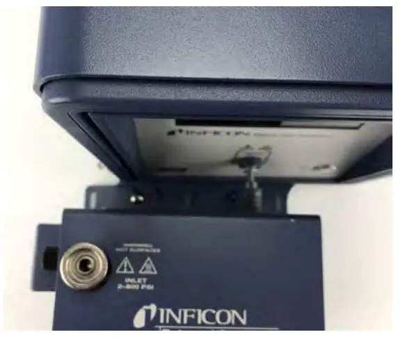
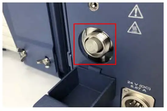
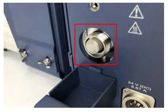
- Gently push the device toward the instrument until the transfer line reaches the front inlet of Micro GC Fusion.
- Loosely thread the front screws into the slide plate using a 3.0 mm hex driver.
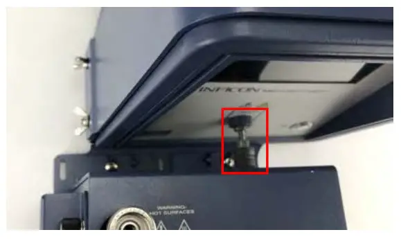
- Tighten the transfer line nut to the front inlet of Micro GC Fusion one-quarter turn past finger-tight using a 5/16 in. wrench.
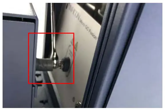
- Slide the rubber insulation sleeve in place to cover the entire inlet line and nut.
- Tighten the front and rear slide plate screws using the 3.0 mm hex driver.
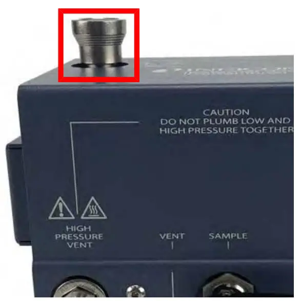
- Attach a 1/8 in. vent line to the HIGH PRESSURE VENT. Tighten it with a 7/16 in. open-ended wrench.
 WARNING
Gas pressure on the HIGH PRESSURE PURGE VENT may be up to 5515 kPa (800 psi). Extreme caution must be taken to avoid personal injury.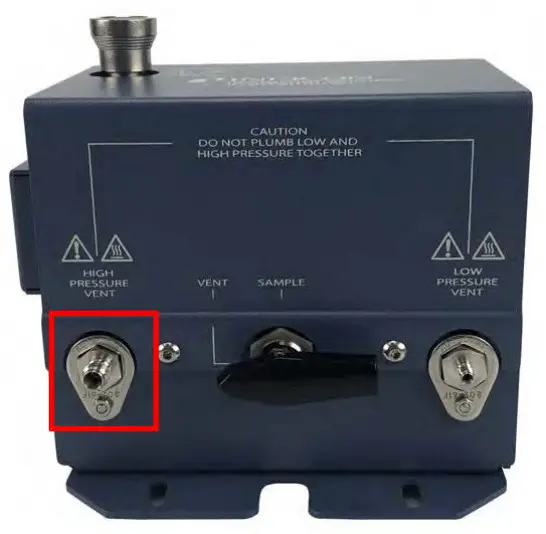
- Attach a 1/16 in. vent line to the LOW PRESSURE VENT. Tighten it with a 5/16 in. open-ended wrench. CAUTION
Do not plumb low and high pressure together.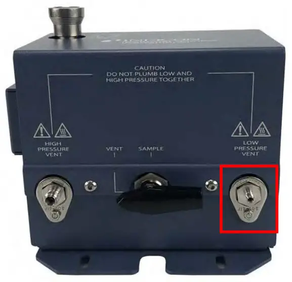
- (Optional) Use the holes in the bottom bracket to mount securely to a horizontal surface. Mounting hardware is not included.
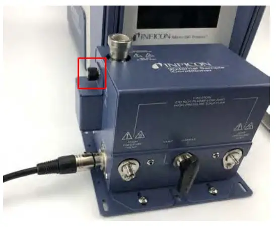
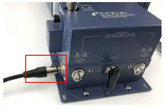
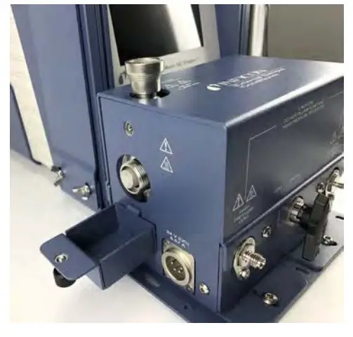
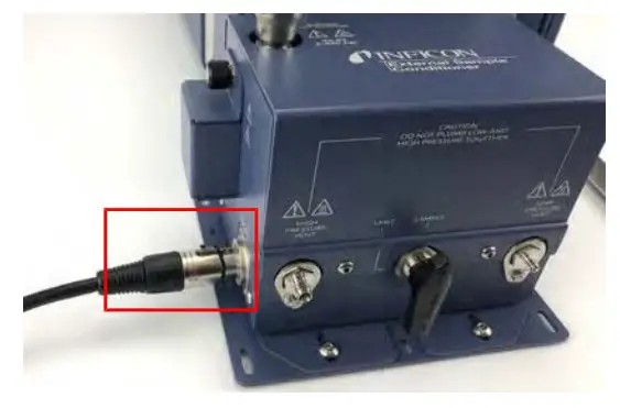
- Attach the power connector to the side of the external sample conditioner.
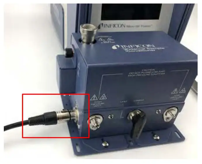
- Plug in the power cord to the power supply and connect to an AC power source.
![]() CAUTION
CAUTION
Only replace the power cord with proper approved cords or contact INFICON to purchase a replacement cord.![]() WARNING
WARNING
Safely vent sample stream vent ports using the appropriate sized tubing for each connection. Potentially toxic, noxious, asphyxiant (oxygen displacing) or flammable gasses should be vented outside Micro GC Fusion and away from the operating area. Vent toxic gases to a fume hood, chemical trap, or reaction medium.
Operation
- Attach a 1/4 in. male Quick Connect (PN 059-0808S) to the sample line.
- Set the sample line pressure regulator to < 5515 kPa (800 psi). WARNING
A pressure regulator must be present on the sample line to ensure that the sample does not exceed 5515 kPa (800 psi). - Attach the 1/4 in. male Quick Connect to the external sample conditioner female quick connect port. It will click into place.
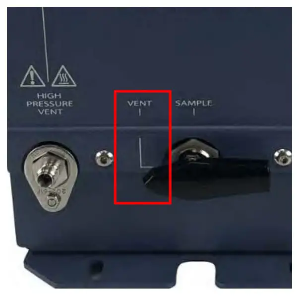
- Before turning the sample on, ensure the manual valve is in the Vent position.
 WARNING
Safely vent sample stream vent ports using the appropriate sized tubing for each connection. Potentially toxic, noxious, asphyxiant (oxygen displacing) or flammable gasses should be vented outside Micro GC Fusion and away from the operating area. Vent toxic gases to a fume hood, chemical trap, or reaction medium. - Turn the sample on and purge for the desired time to ensure an accurate sample. This time will vary depending upon amount of
sample available and the length of the sample line. WARNING
Gas pressure on the HIGH PRESSURE PURGE VENT may be up to 5515 kPa (800 psi). Extreme caution must be taken to avoid personal injury. - Turn the manual valve to the Sample position.
- Conduct a run using Micro GC Fusion software.
- When finished with the sample, shut off the gas source.
- To depressurize the system, slowly turn the manual valve halfway towards the Vent position.
- Monitor the pressure regulator on the sample line. When the regulator reads 0 psi, the external sample conditioner is depressurized and it is safe to remove the sample line.
- Press on the female Quick Connect fitting to release the sample line.
Spare Parts
The following is a list of orderable spare parts:
| Part Number | Description |
| 952-018-G1S
| Transfer line kit (includes one 1/16 in. sample transfer tubing with rubber insulation sleeve and 1/16 in. nut and ferrules) |
| 952-019-G1S
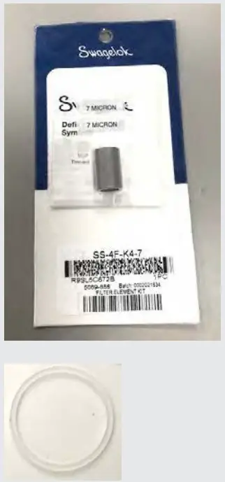
| Filter element kit (includes six 7 µm filters and one gasket) |
| 033-0074S
| Power supply kit (includes one) |
| 952-515-P1S
| Filter cover kit (includes one) |
| 059-0809S
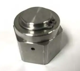
| Bonnet nut kit (includes one) |
| 144-374S
| M5 wing nut kit (includes four) |
| 059-0808S
| Quick stem connector kit (includes one) |
Replacing the Internal Filter on the External Sample Conditioner
To replace the filter (part of PN 952-019-G1S):
- Remove the power cord from the Micro GC Fusion external sample conditioner.
- Ensure the handle is in the vent position and disconnect any sample line(s).
- Let the device cool for a minimum of 20 minutes.
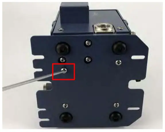
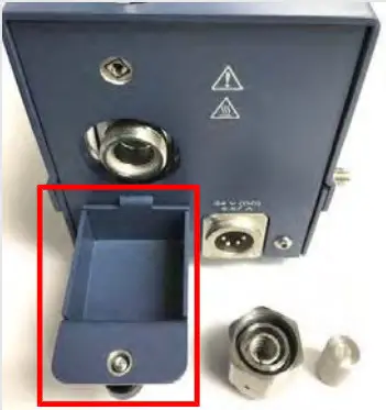
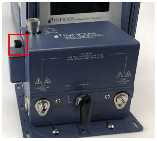
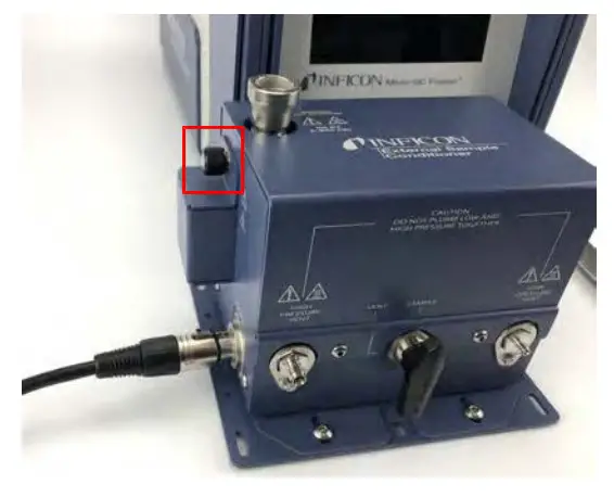
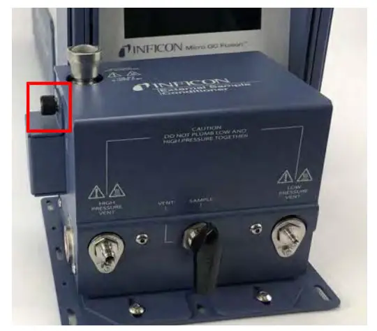
- Unscrew the thumb screw on the side of the device.
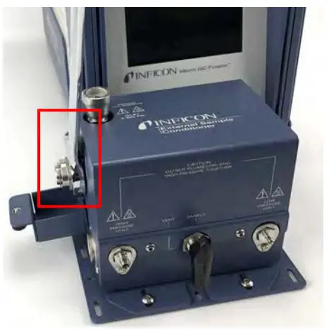
- Lower the filter door (PN 952-515-P1S).
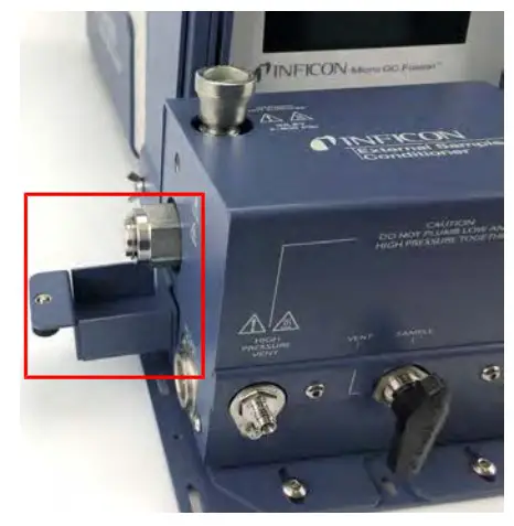
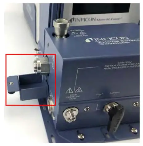
- Using a 1 in. open-ended wrench, loosen the bonnet nut (PN 059-0809S) in a counter-clockwise direction.
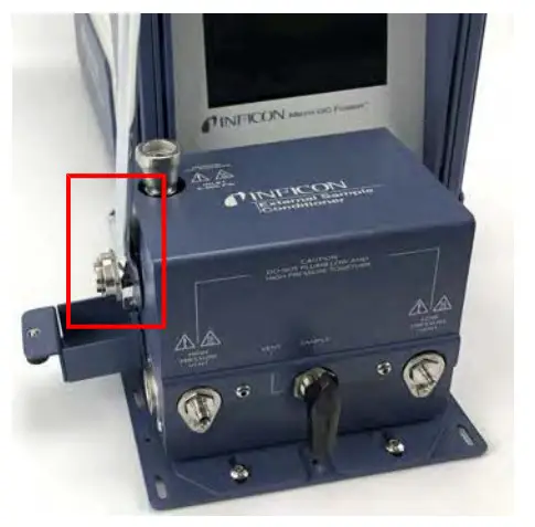
- Remove the bonnet nut.
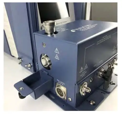 The filter assembly nut is tightened 1/8 turn past finger-tight for high pressure applications.
 - Remove the filter.
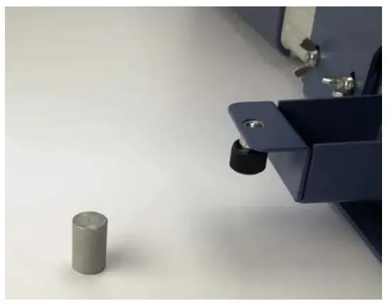
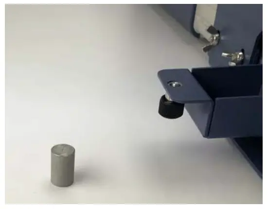
- Replace the 7 µm filter ensuring the 7 is facing outward.
- Re-install the bonnet nut and hand-tighten.
- Using a 1 in. open-ended wrench, tighten 1/8 of a turn past finger-tight.
- Cover the bonnet nut by reattaching the cover door using the thumb screw on the side of the device.
- Reattach the power cord to the external sample conditioner.
Replacing the Gasket on the External Sample Conditioner
To replace the gasket (part of PN 952-019-G1S):
- Remove the power cord from the Micro GC Fusion external sample conditioner.
- Ensure the handle is in the vent position and disconnect any sample line(s).
- Let the device cool for a minimum of 20 minutes.
- Unscrew the thumb screw on the side of the device.
- Lower the filter door (PN 952-515-P1S).
- Using a 1 in. open-ended wrench, loosen the bonnet nut (PN 059-0809S) counter-clockwise.
- Remove the bonnet nut.
 The filter assembly nut is tightened 1/8 turn past finger-tight for high pressure applications.
 - Remove the filter.
- Using a pick, remove the old gasket.
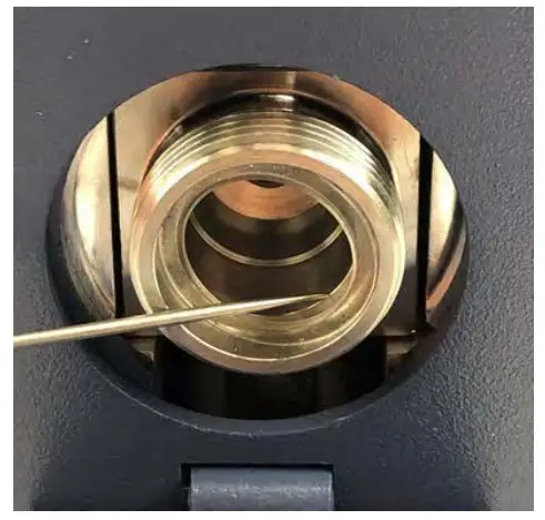
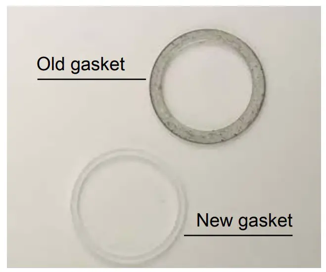
- Using a pick, insert and seat the new gasket.
- Replace the 7 µm filter ensuring the 7 is facing outward.
- Re-install the bonnet nut and hand-tighten.
- Using a 1 in. open-ended wrench, tighten 1/8 of a turn past finger-tight.
- Cover the bonnet nut by reattaching the cover door using the thumb screw on the side of the device.
- Reattach the power cord to the external sample conditioner.
Inspired by visions. Proven by success.
www.inficon.com
[email protected]
Due to our conbnuing program of product improvements, specifications are sub, ect
to change without notice The trademarks mentioned this document are held by the companies that produce them
074-732-P1A
074-732-P1A Micro GC Fusion External Sample
Conditioner Installation Sheet


