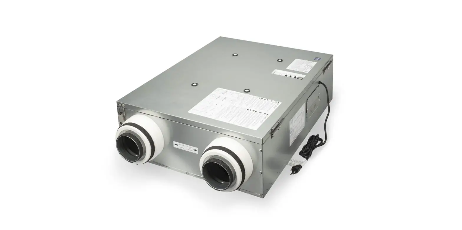
Panasonic FV-10VEC2R Energy Recovery Ventilator Owner’s Manual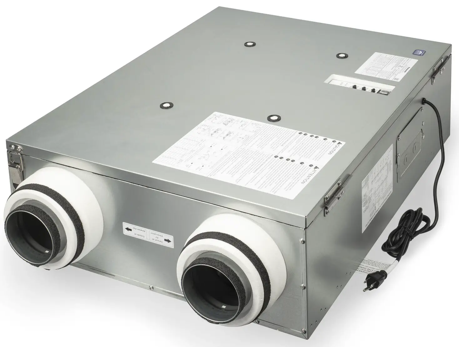
![]() WARNING
WARNING
This service information is designed for experienced repair technicians only and is not designed for use by the general public. It does not contain warnings or cautions to advise non technical individuals of potential dangers in attempting to service a product. Products powered by electricity should be serviced or repaired only by experienced professional technicians. Any attempt to service or repair the product or products dealt with in this service information by anyone else could result in serious injury or death.
IMPORTANT SAFETY NOTICE
There are special components used in this equipment which are important for safety. These parts are marked by in the Schematic Diagrams, Exploded Views and Replacement Parts List. It is essential that these critical parts should be replaced with manufacturer’s specified parts to prevent shock, fire or other hazards. Do not modify the original design without permission of manufacture. We suggest to handle such parts after the static electricity prevention.
It is forbidden to touch the PCB parts by bare hands during the repairing process.
Specifications
Ventilation Performance
| Model No. | Air direction | Voltage (V) | Frequency (Hz) | Duct | Static pressure | Net air flow (CFM) | Power consumption (W) | Weight Lb.(Kg) | |
| Exhaust | Supply | Fan unit | |||||||
| FV-10VEC2R | Exhaust & Supply | 120 | 60 | 4“/6” | 0.1”WG | 100 | 100 | 81 | 50(22.4) |
| 0.4”WG | 100 | 100 | 90 | ||||||
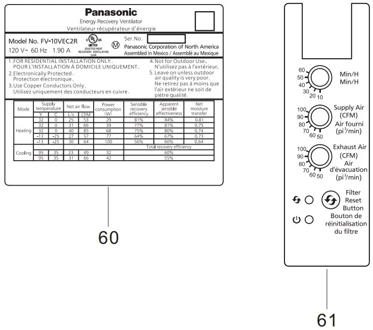
Energy Performance
| Model No. | Mode | Supplytemperature | Net air flow | Power consumption (W) | Sensible recovery efficiency | Apparent sensible effectiveness | Net moisture transfer | ||
| °F | °C | L/s | CFM | ||||||
| FV-10VEC2R | Heating | 32 | 0 | 25 | 53 | 29 | 80% | 83% | 0.78 |
| 32 | 0 | 31 | 66 | 39 | 77% | 81% | 0.74 | ||
| 32 | 0 | 40 | 85 | 68 | 73% | 77% | 0.71 | ||
| -13 | -25 | 27 | 57 | 77 | 65% | 67% | 0.71 | ||
| -13 | -25 | 30 | 64 | 100 | 56% | 60% | 0.58 | ||
| Cooling | Total recovery efficiency | ||||||||
| 95 | 35 | 23 | 49 | 32 | 60% | ||||
| 95 | 35 | 31 | 66 | 42 | 55% | ||||
The testing of the ventilation performance and the energy performance in accordance with CSA-C439 standard.
Parts Identification
Main Body Section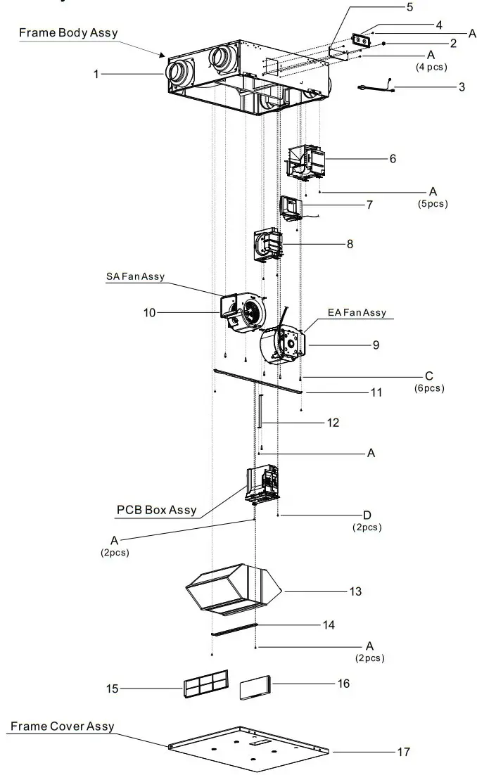
Frame Body Assy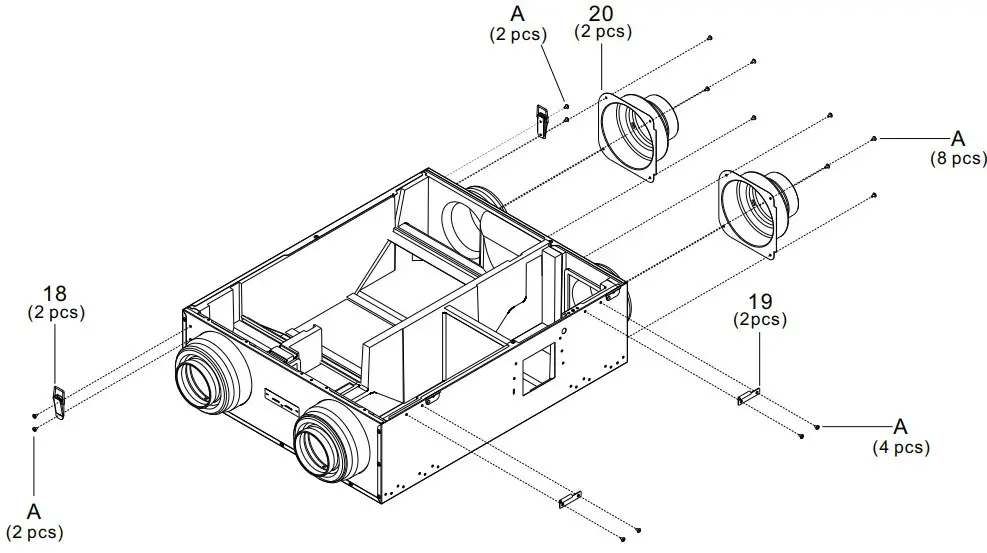
SA Fan Assy / EA Fan Assy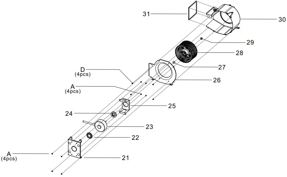
PCB Box Assy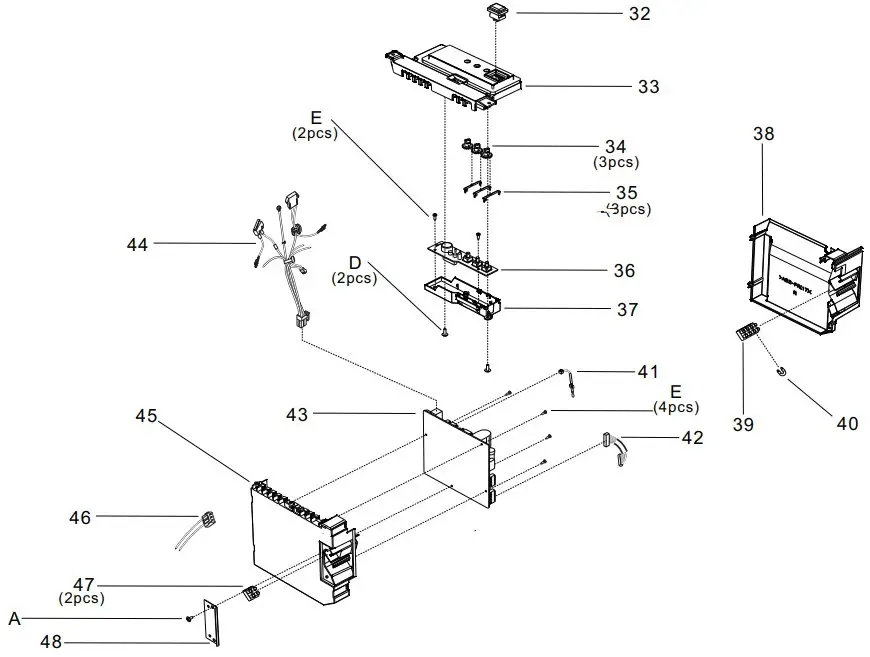
Frame Cover Assy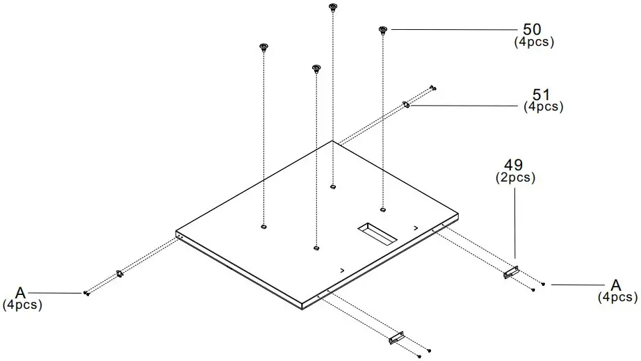
Main Labels
![]() CAUTION
CAUTION
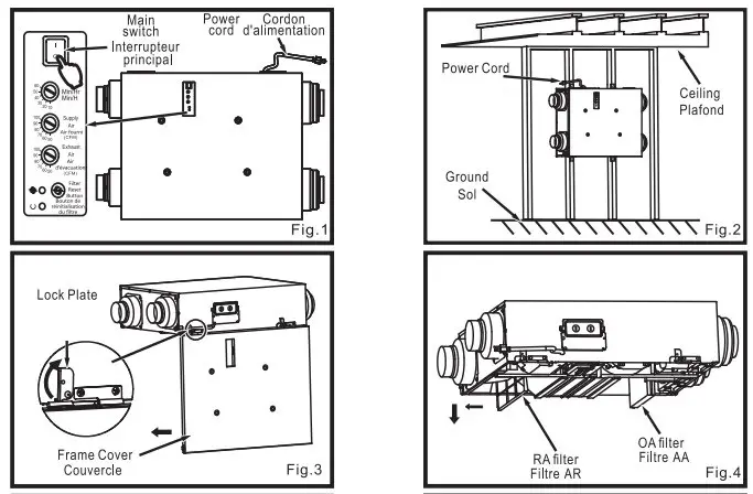
- Electric shock may result. Disconnect power by switching off main switch first, then unplug the power plug before working on unit when it is in default mode. (Fig.1)
- Electric shock may result. Disconnect power by switching off wall switch first, then main switch and unplug the power plug before working on unit when replacing the jumper cable with wall switch.
- The installation direction should refer to Fig.2 ( power cord upward) when wall mounting.
- Routine maintenance must be performed every 2 or 3 months , clogged filters may cause condensation on the unit due to air flow reduction.
- Please wear gloves to avoid pinching fingers during maintenance.
- Please pay attention to dust ,condensation water or parts that may drop down when the cover is opened.
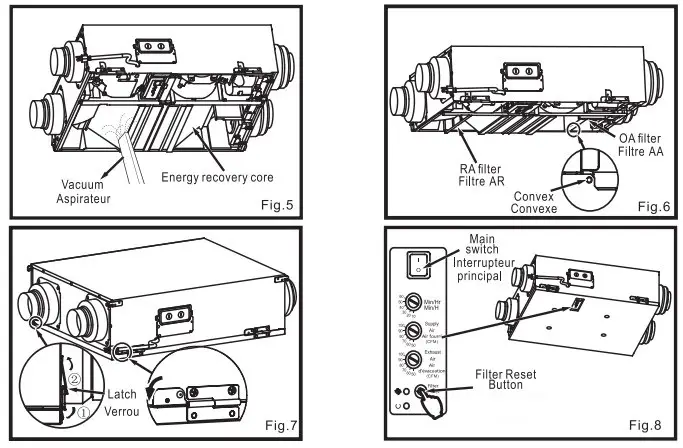
MAINTENANCE PROCEDURE
- Open the frame cover by unlocking the latches. If not convenient for maintenance you also can turn the lock plate 90° and remove the frame cover. (Fig.3)
- Remove OA filter and RA filter to clean with vacuum cleaner. (Fig.4)

- Clean energy recovery core with vacuum cleaner. (Fig.5)
- Replace the OA and RA filters. Make sure the RA filter adapts to the convex and the direction of the arrow on the OA filter is in the same direction as the air flow displayed on the nearby label. (Fig.6)
- Reinstall and close frame cover by locking the latches then reset the lock plate. (Fig.7)
- Connect power, press filter reset button with sound of “Pi-” then filter indicator and buzzer sound will be off. (Fig.8)
The relation between volume and differential pressure (reference).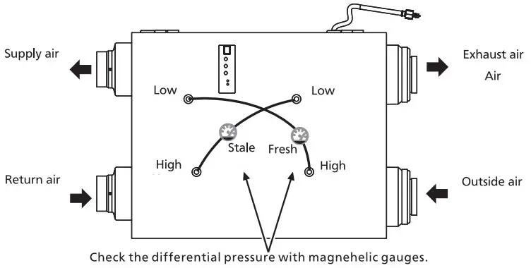
| Volume (CFM) (pi3/min) | Fresh | Stale (Pa) |
| FV-10VEC2R | ||
| 50 | 35 | 45 |
| 60 | 45 | 60 |
| 70 | 60 | 80 |
| 80 | 75 | 105 |
| 90 | 100 | 140 |
| 100 | 115 | 190 |
Packing Case Assy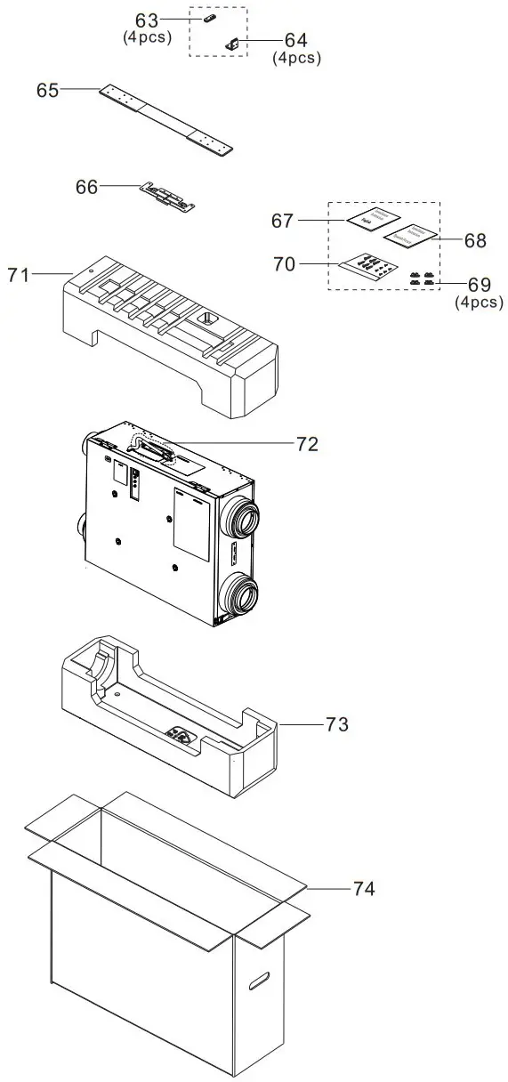
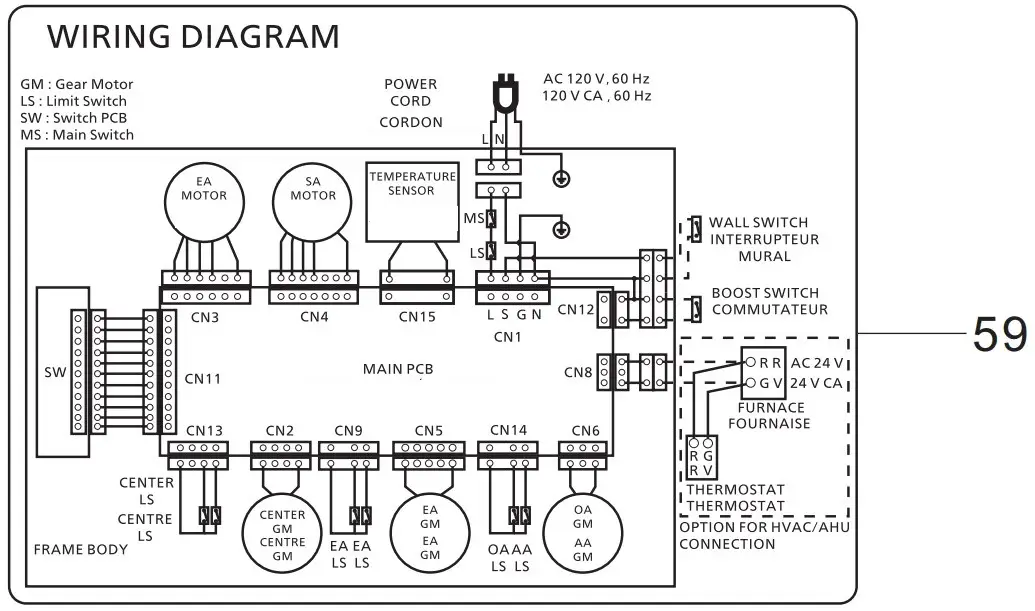
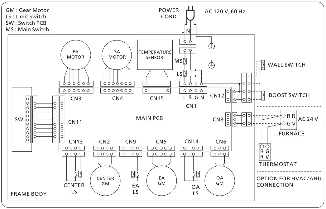
Wiring diagram
Troubleshooting
If a problem is encountered, please investigate it by going through the following items. If the problem still persists, please disconnect the power and contact the dealer for repair.
| Problem | Display | Action | |
| Running indicator (Green) | Filter indicator (Red) | ||
| The ERV doesn’t work. | Off | Off |
|
| On | Off |
| |
| The HVAC/AHU doesn’t work when ERV works. | On | Off | Please disconnect the power and contact the dealer to check the HVAC/AHU wiring connect. |
| Buzzer sound (10 sec in a hour) and ERV works. | On | On | The RA filter and OA filter need to be maintained. If you do not want the buzzer notification, please long press the filter reset button for 3 sec to cancel it. |
| Buzzer sound (30 sec in a hour) and ERV doesn’t work. | Blink* (0.5 s) | Off | SA motor error, please disconnect the power and contact the dealer for repair. |
| Blink* (2 s) | Off | EA motor error, please disconnect the power and contact the dealer for repair. | |
| Off | Blink* (0.5 s) | OA damper error, please disconnect the power and contact the dealer for repair. | |
| Off | Blink* (2 s) | EA damper error, please disconnect the power and contact the dealer for repair. | |
| Off | Blink* (4 s) | Center damper error, please disconnect the power and contact the dealer for repair. | |
| Blink* (0.5 s) | On | Temperature sensor error, please disconnect the power and contact the dealer for repair. | |
| On | Blink* (0.5 s) | PCB board error, please disconnect the power and contact the dealer for repair. | |
| ERV doesn’t work base on the setting air volume. | On | Off |
|
The time under “Blink” means the frequency of blink.
Parts List
Main Body Section
| No. | Part No. | Part Name | Q´ty | Remark |
| 1 | FFV1600174M | Frame Body Assy | 1 | |
| 2 | FFV0720012S | Cord Bushing | 1 | |
| 3 | FFV4620115S | Power Cord | 1 | |
| 4 | FFV6710047S | Wiring Cover | 1 | |
| 5 | FFV3740038S | Maintenance Plate | 1 | |
| 6 | FFV3402188M | EA Damper Assy | 1 | |
| 7 | FFV4710448M | Center Damper Assy | 1 | |
| 8 | FFV4300151M | OA Damper Assy | 1 | Include Temperature Sensor |
| 9 | FFV3402189M | EA Fan Assy | 1 | |
| 10 | FFV3702280M | SA Fan Assy | 1 | |
| 11 | FFV1600153M | Frame Bracket Assy | 1 | |
| 12 | FFV1600154S | Frame Bracket Hook | 1 | |
| 13 | FFV3402190S | Element Assy | 1 | |
| 14 | FFV3402191S | Element Holder | 1 | |
| 15 | FFV6730102S | RA Filter | 1 | |
| 16 | FFV4300152S | OA Filter M8 | 1 | Merv 8 |
| 17 | FFV1600175M | Frame Cover Assy | 1 | |
| A | FFV7000074S | Truss Tap Screw | 17 | |
| B | FFV7030008S | Pan Screw | 2 | |
| C | FFV7000224S | PS Screw | 6 | |
| D | FFV7000089S | Truss Tap Screw | 2 |
Frame Body Assy
| No. | Part No. | Part Name | Q´ty | Remark |
| 18 | FFV3440021S | Latch | 2 | |
| 19 | FFV2220075S | Hinge B | 2 | |
| 20 | FFV0000163S | Adapter | 2 | |
| A | FFV7000074S | Truss Tap Screw | 16 |
SA Fan Assy/EA Fan Assy
| No. | Part No. | Part Name | Q´ty | Remark |
| 21 | FFV3730127M | Motor Holder Plate | 1 | |
| 22 | FFV2230022S | Holder Gum(B) | 1 | |
| 23 | FFV3402192M | EA Motor Assy | 1 | |
| (23) | FFV3702281M | SA Motor Assy | 1 | |
| 24 | FFV2230023S | Holder Gum(A) | 1 | |
| 25 | FFV3730128M | Motor Holder | 1 | |
| 26 | FFV3730129M | Motor Base | 1 | |
| 27 | FFV7010055S | Washer | 1 | |
| 28 | FFV1610079M | Blade | 1 | |
| 29 | FFV7020022S | Nut | 1 | |
| 30 | FFV4710409M | Casing | 1 | |
| 31 | FFV4710408M | Casing Packing | 1 | |
| A | FFV7000074S | Truss Tap Screw | 8 | |
| D | FFV7000089S | Truss Tap Screw | 4 |
PCB Box Assy
| No. | Part No. | Part Name | Q´ty | Remark |
| 32 | FFV5580017S | Switch Assy | 1 | |
| 33 | FFV5580016M | Switch PCB Cover Assy | 1 | |
| 34 | FFV5580010S | Switch Knob | 3 | |
| 35 | FFV5580011S | Switch Spring | 3 | |
| 36 | FFV5580018M | Switch PCB Assy | 1 | |
| 37 | FFV5580019M | Switch PCB Box Assy | 1 | |
| 38 | FFV4690039M | PCB Cover | 1 | |
| 39 | FFV5820040S | Terminal | 1 | |
| 40 | FFV2800028S | Jumper Cable | 1 | |
| 41 | FFV5820037M | Temperature Sensor | 1 | |
| 42 | FFV5580020M | Switch PCB Wire | 1 | |
| 43 | FFV3740055M | Main PCB Assy | 1 | |
| 44 | FFV4690040M | Power Connect Wire | 1 | |
| 45 | FFV4690027M | PCB Box | 1 | |
| 46 | FFV0000164M | AHU Wire | 1 | |
| 47 | FFV5820038S | Terminal | 1 | |
| 48 | FFV4690028S | Partition Plate | 1 | |
| A | FFV7000074S | Truss Tap Screw | 1 | |
| D | FFV7000089S | Truss Tap Screw | 2 | |
| E | FFV7000102S | Pan Tap Screw | 6 |
Frame Cover Assy
| No. | Part No. | Part Name | Q´ty | Remark |
| 49 | FFV2220076S | Hinge A | 2 | |
| 50 | FFV4620133S | Pressure Plug | 4 | |
| 51 | FFV3440022S | Latch Base | 2 | |
| A | FFV7000074S | Truss Tap Screw | 8 |
Main Labels
| No. | Part No. | Part Name | Q´ty | Remark |
| 52 | FFV3740056M | Maintenance Label | 1 | |
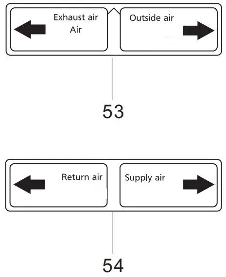
| 53 | FFV3402226M | EA OA Adapter Label | 1 | |
| 54 | FFV6730113M | RA SA Adapter Label | 1 | |
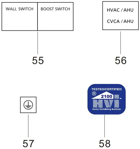
| 55 | FFV5580031M | Wall Switch Label | 1 | |
| 56 | FFV0000189M | AHU Label | 1 | |
| 57 | FFV3402194S | Earth Label | 1 | |
| 58 | FFV2260002S | HVI Mark | 1 | |
| 59 | FFV6710056M | Wiring Label | 1 | |
| 60 | FFV4020991M | Name Plate | 1 | |
| 61 | FFV5580022S | Switch Label | 1 | |
| 62 | FFV4690029S | Power Cord Label | 1 |
Packing Case Assy
| No. | Part No. | Part Name | Q´ty | Remark |
| 63 | FFV4710410S | Ceiling Inst. Plate | 4 | |
| 64 | FFV3440023S | L Plate | 4 | |
| 65 | FFV6710049S | Wall Install Bracket | 1 | |
| 66 | FFV2220077S | Hanger | 1 | |
| 67 | FFV2540249M | Installation Instructions | 1 | English |
| 68 | FFV2540250M | Installation Instructions | 1 | Spanish,For USA Market. |
| (68) | FFV2540251M | Installation Instructions | 1 | French,For CA Market. |
| 69 | FFV5580023S | Screw Cover | 4 | |
| 70 | FFV0010253S | Accessory For Screws | 1 | |
| 71 | FFV4710411S | Packing Pad Top | 1 | |
| 72 | FFV4650038S | Poly Cover | 1 | |
| 73 | FFV4710412S | Packing Pad Bottom | 1 | |
| 74 | FFV9001430M | Packing Case Assy | 1 |


