
MARK-10 F1505S Test Frames User Guide
Thank you!
Thank you for purchasing a Mark-10 Series F Test Frame. With proper usage, we are confident that you will get many years of great service with this product.
Mark-10 instruments are ruggedly built for many years of service in laboratory and industrial environments.
Please read through this Quick Start Guide and the complete User’s Guide before use.
IN THE BOX
| Qty | Description |
| 1 | Control panel, mounting bracket, and hardware (-IMT models only) |
| 1 | USB flash drive containing software installation files (-IM models only) |
| 1 | USB dongle (-IM models only) |
| 1 | USB cable -IMT models: right-angle C to B -IM models: A to B |
| 1 | Eye end kit for base |
| 2 | Lock ring for eye end |
| 2 | Spanner wrench |
| 1 | Power cord |
| 1 | Allen wrench set |
SETUP
Place the test frame on a clean, flat and level work area free from vibration. Ensure that the rear of the column is easily accessible to connect the power cord and connection cables. To prevent tipping, it is suggested to mount the test frame to a work bench via screws fastened into the underside of the base. Connect the power cord to an outlet.
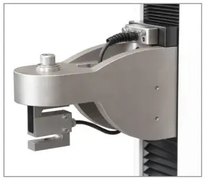
INSTALLING A FORCE SENSOR
Install the sensor to the underside of the crosshead using the supplied socket head screw and hardware. Plug the connector into the connector into the receptacle in the top front surface of the crosshead, then fasten the two thumbscrews, as shown at left. Grips and fixtures may be threaded onto the underside of the sensor.
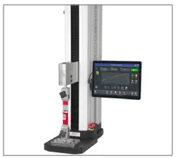
INSTALLING THE CONTROL PANEL (-IMT MODELS)

Test frame part numbers ending in “-IMT”, for example Model F1505 IMT, include a Windows tablet with attached ball mount and mounting bracket, packaged separately. The mounting arm is pre-installed into the front right slot in the test frame column via two screws.
Loosen the knob sufficiently to slide the ball, mounted to the rear of the tablet, into the arm. Orient the tablet horizontally, with the USB-C port positioned on the left side. Adjust the viewing angle as desired, then tighten the knob.
Connect the included USB cable between the USB-C port and the USB-B port in the rear of column, and connect the AC adapter connector.
Plug in the AC adapter and press the Power button, in the lower right corner of the tablet. The tablet will boot up directly into the IntelliMESUR application. If not, select the IntelliMESUR® icon in the Windows home screen.

INSTALLING THE SOFTWARE (-IM MODELS)
For model numbers ending in “-IM”, a separate license is provided to install onto the user’s device. Locate the box containing a USB flash drive and USB dongle, as shown at left.
Plug in the flash drive, then locate and double-click the file “setup.exe”. Refer to the User’s Guide for complete instructions.
FURTHER INFORMATION
User’s Guide
www.mark-10.com/downloads/product-downloads/manualSeriesF.pdf

Download user’s guides, data sheets, software, solid models, and more.
www.mark-10.com/downloads

Force and torque measurement engineered better
Mark-10 Corporation
11 Dixon Avenue
Copiague, NY 11726
888-MARK-TEN
Tel: 631-842-9200
Fax: 631-842-9201
www.mark-10.com
[email protected]


