![]()
Operator’s manual
Track&Trace
Order Information
Please specify when ordering this document:
Operator’s manual
Track & Trace
Edition 2020-10-01
Document number B1105en
Address for orders
TRUMPF GmbH + Co. KG
Technische Redaktion
Johann-Maus-Straße 2
D-71254 Ditzingen
Fon: +49 7156 303 – 0
Internet: http://www.trumpf.com
E-Mail: [email protected]
Safety
Overview of residual risks
| Residual risk | Hazard area | Type of danger | Measure to be taken by the user |
| Mechanical hazard | |||
| Bruises or knocks due to falling satellites | Satellite | Risk of injury | Cordon off the work area below the assembly area. Use the enclosed brackets or own-construction brackets according to the Operator’s manual. Use the screw locks. |
| Bruises knock due to falling charging station | Charging station | Secure the charging station to the wall or table using screws/bolts. | |
| Slipping, stumbling, falling overcharging station placed in the path | Charging station | Secure the charging station to the wall or table using screws/ bolts. | |
| Bruises or knocks due to a falling industrial PC | Industrial PC | Secure industrial PC to wall or table using screws/bolts. | |
| Slipping, stumbling, falling over industrial PC placed in the path | Industrial PC | Secure industrial PC to wall or table using screws/bolts. | |
| Falling from lifting device/ladder | Lifting device/ladder | Use suitable lifting devices and ladders. These should be assembled by qualified personnel only. | |
| Cuts due to edge of satellite retaining bracket | The sharp edge of the retaining bracket | During assembly, wear gloves. | |
Residual risks
Tab. 1
FCC – safety, and compliance
This device complies with Part 15 of the Federal Communications Commission (FCC) Rules. Operation is subject to two conditions: (1) this device may not cause harmful interference, and (2) this device must accept any interference received, including interference that may cause undesired operation.
This equipment has been tested and found to comply with the limits for a Class B digital device, pursuant to Part 15 of the FCC Rules. These limits are designed to protect reasonably against harmful interference in a residential installation.
This equipment generates, uses, and can radiate radio frequency energy and, if not installed and used in accordance with the instructions, may cause harmful interference to radio communications. However, there is no guarantee that interference will not occur in a particular installation.
If this equipment does cause harmful interference to radio or television reception, which can be determined by turning the equipment off and on, the user is encouraged to try to correct the interference by one of the following measures:
- Reorient or relocate the receiving antenna,
- Increase the separation between the equipment and receiver,
- Connect the equipment into an outlet on a circuit different from that to which the receiver is connected,
- Consult the dealer or an experienced radio/TV technician for help.
![]() CAUTION
CAUTION
This equipment, the satellites, and the markers may only be operated indoors.![]() Operation outdoors is in violation of 47 U.S.C. 301 and could subject the operator to serious legal penalties.
Operation outdoors is in violation of 47 U.S.C. 301 and could subject the operator to serious legal penalties.
![]() CAUTION
CAUTION
This equipment may only be operated as a fixed installation.![]() Mobile operation is in violation of 47 U.S.C. 301 and could subject the operator to serious legal penalties.
Mobile operation is in violation of 47 U.S.C. 301 and could subject the operator to serious legal penalties.
![]() CAUTION
CAUTION
UWB devices may not be employed for the operation of toys.![]() Operation onboard an aircraft, a ship, or a satellite is prohibited.
Operation onboard an aircraft, a ship, or a satellite is prohibited.
![]() CAUTION
CAUTION
Changes or modifications![]() Any changes or modifications not expressly approved by TRUMPF could void the user’s authority to operate this equipment.
Any changes or modifications not expressly approved by TRUMPF could void the user’s authority to operate this equipment.
The Satellites only operate (i.e. receive and transmit UWB signals) within a complete UWB real-time location system TRUMPF RTLS, which must be professionally installed. The installed system is configured to cover only the area inside the building, preventing the Satellites and other UWB devices of the system from emitting UWB signals outdoors. Contact your system administrator if you are unsure as to the extent of coverage. .
The local representative in terms of the Federal Communications Commission (FCC) for the USA is:
Anupam Chakraborty
TRUMPF Inc.,1900 W Central Road, 60192 Hoffman Estates, USA
Phone +775 (842) 3420
Intended use
Track&Trace
The system is designed for localization during sheet metal processing.
The user is allowed to monitor the location of production orders, load carriers, vehicles, and tools with the system.
Installation, operating and transport conditions defined by TRUMPF must be adhered to and maintenance work must be carried out in accordance with the Operator’s manual. The user must observe the specifications of the country in which the machine is being operated as well as national and regional safety and accident prevention regulations.
The following is not permitted:
- Unauthorized alteration or conversion of the system by the user or personnel.
- Any working procedure that impairs the safety.
NOTICE
Persons carrying markers might be monitored.
Processing of personal data.![]() People must not be given markers.
People must not be given markers.![]() This creates personal data which, according to the European General Data Protection Regulation, can only be processed under defined requirements.
This creates personal data which, according to the European General Data Protection Regulation, can only be processed under defined requirements.![]() Observe the intended use.
Observe the intended use.
Note
CAUTION: This equipment may only be operated as a fixed installation. Mobile operation is in violation of 47 U.S.C. 301 and could subject the operator to serious legal penalties.
Disclaimer
Any use going beyond this is considered to be unauthorized use. TRUMPF is not liable for any damage, especially personal injury and damage to property as well as production failures resulting from this. The risk is borne solely by the user. The warranty will be voided.
Frequencies and transmitting power
The following frequencies are used:
UWB: 3.25 GHz – 4.75 GHz Max Mean power (EIRP) -41.3 dBm/Mhz
BLE: 2.4 GHz – 2.48 GHz Max power (EIRP) 4 dBm
ZigBee: 2.4 GHz – 2.48 GHz Max power (EIRP) 4 dBm
Climatic requirements
| Operating temperature of the system | 0 °C (+32 °F) to +45 °C (+113 °F) |
| Loading operation temperature marker | 0 °C (+32 °F) to +39 °C (+102 °F) |
| Relative humidity | max. 100 % at +24 °C (+75 °F) |
Disassembly and disposal
TRUMPF recommends commissioning a Technical Service or a specialist disposal company for the dismantling and disposal of a machine, component, or system. The information below must be passed on to the specialist company performing the disposal work.
Hazardous materials
Always dispose of batteries and rechargeable batteries in satellites and markers in accordance with the national regulations.
Area of application: Europe
In Europe, the duty to communicate information is applicable in accordance with Article 33 of the REACH agreement. TRUMPF products contain components whose lead content is above the limit value of 0.1 percent by weight. Lead is found in alloys and does not constitute a danger.
Data management
Track&Trace supports employees in their production processes and logistics and increases their productivity. Furthermore, Track&Trace offers the possibility to create transparency in production based on material flow data. Production can be improved based on the data evaluation. This document describes which data is collected, as well as how it is transmitted and processed.
| Data type | Brief description & examples |
| Operating status | Data concerning system configuration and system status (device status, location status, faults). |
| Diagnostics data | Message data (e.g. malfunction files). |
| Environmental data | The air pressure in the satellite and marker is measured and used to better determine the height of the marker. |
| System usage behavior | Data such as access to the Track&Trace user interface or operation of the interface allow conclusions to be drawn for optimizing production. |
| Motion data | Data and parameters that describe the location of an object (including position information from sensors, and time stamps). |
| Order Data | Data and parameters that make up the order data for a component (including order ID, and customer ID). Logical assignments of order data to sensors or other components are also transmitted. |
| Production hall layout data | Data and information on the structure of the production hall (including an overview of the set-up machines) as well as data and parameters defining virtual zones (in particular what are referred to as “geofences”) and associated entry and exit events. |
Data range
Tab. 3
Data transfer
The data is encrypted and transferred to the TRUMPF Cloud via a secure connection. There, the data is stored in an encrypted format. The Cloud environment makes use of third-party services. Only members of the Track&Trace development team (research, development, and service) have access to this data.
Data processing
The data can be transferred to storage locations at TRUMPF with restricted access so as to be evaluated and so new functionalities can be developed.
Technical Data
Marker
| Housing material | ABS/PC, PC, TPU |
| Weight | 160 g |
| Load | 8 hours (100%) with supplied charging station |
| Temperature | -10°C +39°C |
| Radio | UWB: 3.25 GHz – 4.75 GHz Max Mean power (EIRP) -41.3 dBm/Mhz BLE: 2.4 GHz – 2.48 GHz Max power (EIRP) 4 dBm ZigBee (sensor network IEEE 802.15.4): 2.4 GHz – 2.48 GHz Max power (EIRP) 4 dBm |
| E-Ink display | 2.7″, resolution 264 x 176 pixels |
| LED | RGB-LED ring for user interaction |
| Mounting | Rubber surface, fastening kit with belt clip, magnets, cable ties, and screws (see below) |
| Certification | CE |
| Geometry | 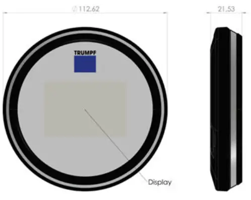 |
| Fastening kit | 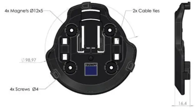 |
| Belt clip (removable) | 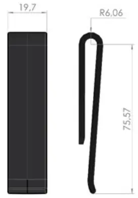 |
Satellite
| Housing material | ABS/PC, PC, TPU |
| Weight | 460 g |
| Power | USB-C, Power over Ethernet (PoE) (PoE IEEE 802.3af (Class 0) 0.44 to 12.95W) RJ45 |
| Temperature | 0°C – +45°C |
| Radio | UWB: 3.25 GHz – 4.75 GHz Max Mean power (EIRP)-41.3 dBm/Mhz BLE: 2.4 GHz – 2.48 GHz Max power (EIRP) 4 dBm ZigBee (sensor network IEEE 802.15.4): 2.4 GHz – 2.48 GHz Max power (EIRP) 4 dBm |
| LED | RGB-LED ring for diagnostics |
| Mounting | Supplied fastening kit |
| Certification | CE |
| Geometry | 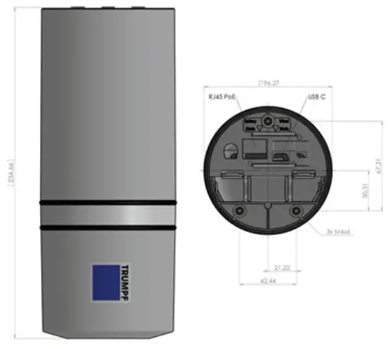 |
Operation
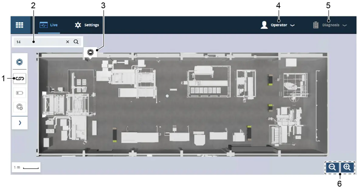
- Dialog for linking markers
- Search box for filtering the markers
- Marker position in the product overview
- Changing the user role
- Diagnostic list
- Zooming view in/out
User interface
Fig. 101300
More information at: www.trumpf.com
Settings
Various settings may be modified. Firstly there are general settings, then there are other options for the hall plan view.
General settings:
- Language
- Measurement units
- Time zone
Settings for the hall plan view:
- Showing the zero point
- Showing the auxiliary grid
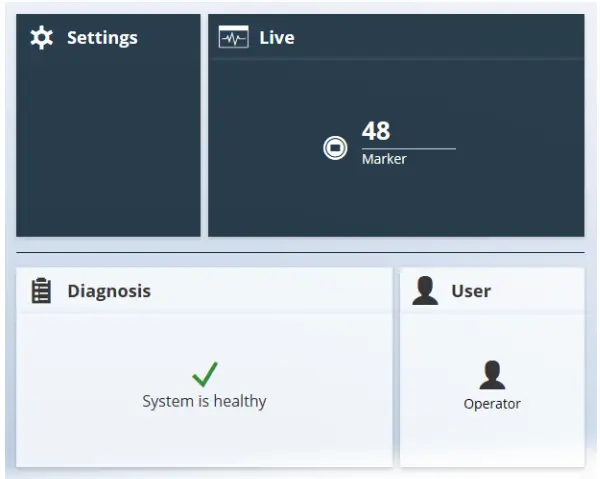
Start screen with dashboard
The start screen shows a dashboard with various functions.
User management
There are two user roles, operator and administrator.
- Operators can manage markers and orders.
- Administrators can also set up satellites and modify the setup using the hall plan.
Meaning of the LED lamps
| Explanation | Color/behavior |
| Charging active | Yellow (slow flashing) |
| Position measurement | Green (short flashing) |
| Position measurement unsuccessful | Red (short flashing) |
| Searching for marker | Red (rapid flashing) |
| Linking successful | White (running light) |
| Link dropped | White (running light) |
| Battery level low | Red (slow flashing) |
LED marker
Tab. 6
| Explanation | Color/behavior |
| Satellite not connected | Red (slow flashing) |
| The satellite is dialing into the network | Blue |
| Satellite connected | White (illuminated) |
LED satellite
Tab. 7
Live view of markers and orders
In the live view, markers and orders can be found directly via the search.
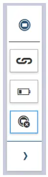
Fig. 98109
Filtering the markers
Using the filter for markers, you can find certain markers. Press the symbol on the hall plan to highlight the marker.
The view in the filtered list corresponds to the hall plan view.
- On the >Marker menu, the following filters can be applied:
− Markers associated with an order are displayed and the “Connect” dialog opens up (see below).
− Markers with a low battery capacity are displayed.
− Markers without order are displayed. - In the “Connect” dialog, orders (grouped by categories) or marker numbers can also be searched for.
Displaying the marker details
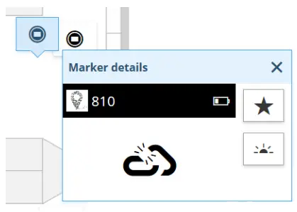
![]() In the hall plan, click on a marker to display the marker details.
In the hall plan, click on a marker to display the marker details.
− Number of markers
− Battery status
− Connected or unconnected status
Tip
Click on the star to display the marker as a favorite regardless of a filter.
Switching on and resetting the marker
- Pull the enclosed magnet over the TRUMPF logo in order to switch on the marker.
The marker only has to be switched off in the event of malfunctions. - Hold the magnet over the TRUMPF logo for about 5 seconds in order to reset the marker.
The marker lights up yellow and “reassociate” appears on the E-Ink display (delivery condition).
Connecting a marker with an order
Markers and orders can also be input via a scanner.
- Press
 .
. - Select the order category.
- Select an order.
Note
Several markers can be assigned to different orders. - Select marker.
■ The marker is marked as connected.
■ Once the order has been processed, the marker can be removed from the order again using the same dialog.
Charging a marker
The markers can be charged in the supplied charging station.
Up to 10 markers can be charged. The charging station can be mounted on a base or suspended from above. It has a power connection and a switch for switching on and off.
Note
The charging station is only suitable for charging markers.
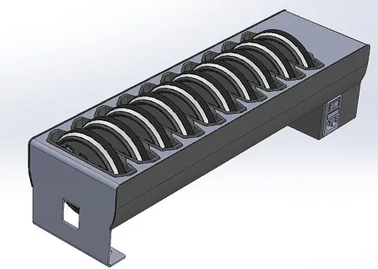
Charging station
Fig. 98118
- Place the marker in the charging station. Switch on the charging station.
The LED of the marker flashes yellow during the charging procedure.
The E-Ink display shows the charging status of the marker. - When the markers are charged, remove the markers and switch off the charging station.
Diagnostics
In the >diagnosis menu, messages on the battery status or regarding the connection between satellites and markers are listed.
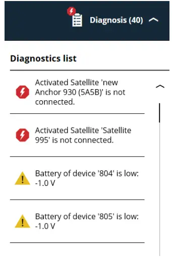
Example diagnostics
Fig. 96601
Accessories and software
For service purposes, it is recommended for the TeamViewer program to be installed on the company computer that accesses the Track&Trace industrial PC.
Spare parts list
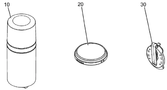
Fig. 98116
| Position | Material-NO. | Designation |
| 10 | 2417477 | Satellite |
| 20 | 2417475 | Marker |
| 30 | 2417474 | Adapter |


