![]()
TRUMPF KG 2564360-01 Track and Trace Marker
Components included
There are different package sizes. The number of satellites and markers differs depending on the package size.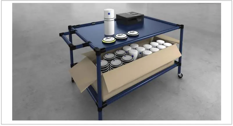
Satellite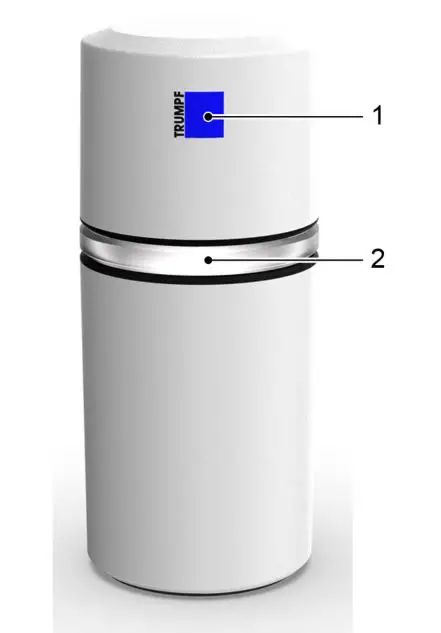
- TRUMPF logo (also used as a reference point during calibration)
- LED status ring
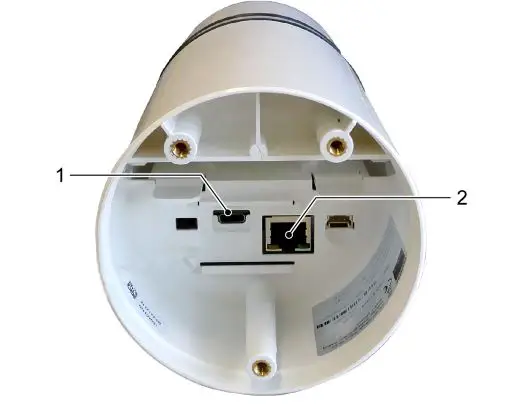
- USB-C connection (power supply)
- Ethernet port (power supply and data transmission)
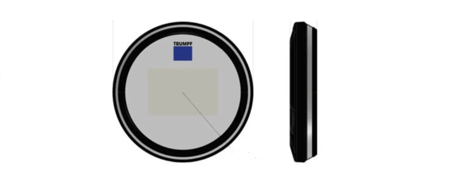
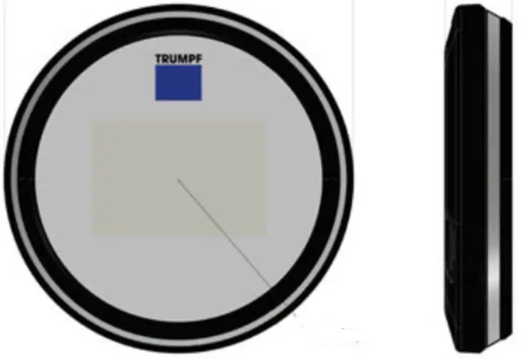
Marker 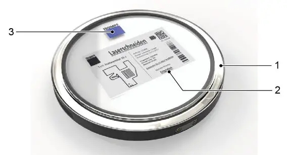
- LED status ring
- E-Ink display
- TRUMPF logo
The marker is charged by induction.
Fastening set for markers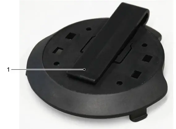
- Fastening clip
Charging station for markers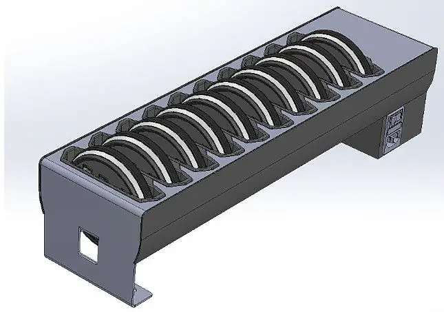
Preinstalled industrial PC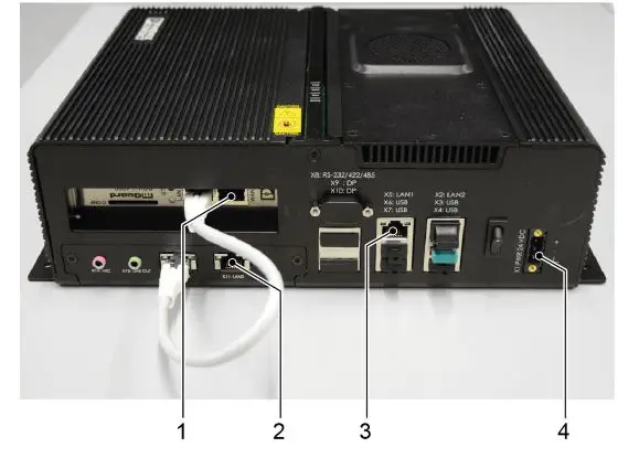
- Connection to customer’s network
- Satellite network connection
- Start-up of the service port
- Power supply
Customer checklist for installation preparation
| No. | Designation | Number | Remark | |
| 1 | Track&Trace components | 1 | Contents: satellites, operator’s manual, markers, industrial PC, holders | |
| 2 | Current hall plan / layout | min. 1 | Hall plan as background for the user interface (see “Preparing the hall plan”, pg. 7) | |
| 3 | Fastening material (screws, dowels, cable ties, etc.) | Depending on the position and type of mounting devices | Assembly accessories for fixing the mounting devices including satellites | |
| 4 | Own assembly tools | – | Drill for dowels and screws | |
| 5 | Conductor | min. 1 | Ladder should be tall enough to allow the satellites to be mounted safely | |
| 6 | Boom lift | 1 | A boom lift or “cherry picker” must be used depending on the ceiling height | |
| 6.1 | Operator for boom lift | 1 | An authorized operator is required to operate the boom lift | |
| 7 | Network cable | Depending on the area of the hall or the sec- tion | Power supply of the satellites via PoE (Power over Ethernet) | |
| 8 | Patch cable | 1 | Data connection between industrial PC and your computer or main satel- lite | |
| 9 | PoE capable switch (does not need to be managed) | Depending on network routing (min. number of satellites plus 1 port) | Power supply and data connection of the satellites | |
| 10 | Device / laptop / desktop PC | 1 | Required for setting up the user interface (browser: Google Chrome, Mozilla Firefox, Windows Edge or Apple Safari) |
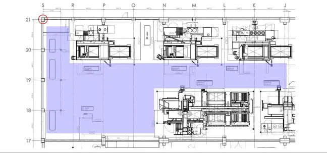
Preparing the hall plan
An up-to-date and suitable hall plan must be available at the commissioning date. A walk-through inspection of the hall is necessary in order to take into consideration the on-site conditions. The hall plan used also serves as a basic map for the localization in the user interface, and must meet certain requirements.Errors in the plan can lead to deviations in the marker position in the user interface.
- The hall plan must be up-to-date; high bay storage racks, machines and other obstructions must be marked.
- The hall plan must be exact, true to scale and dimensioned; the dimensions must refer to one zero point (ideally in the top left corner).

Installation of the system
Mounting satellites
The mounting position of the satellites is made available on a case-by-case basis by TRUMPF.
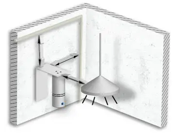
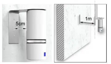
Instructions for assembly
- The distance to cable bundles, cable racks and other electrical interference sources must be at least 1 m.

- Ideally directly on the wall, otherwise the distance to the wall must be < 5 cm or > 1 m. Interference (echo) occurs depending on the distance to the wall. The satellite must be located either very close to the wall or (e.g. when mounted on a ceiling) at a distance of at least 1 m from the wall.
Note:Use brackets supplied by TRUMPF!
Fastening methods
There are three methods for fastening the satellite.
- Holder (fastened in drilled holes in the wall)
- Magnet with arrester loop
- Mounting by clamping
Notes
- Do-it-yourself holders must not enclose or shield the satellite, so that the signal is not interfered with.
- The TRUMPF logo must always point toward the tracking area.
Means, Tools, Materials
- Brackets for wall, ceiling or free-standing assembly. Drawing data can be found at:
- https://www.trumpf.com/en_US/products/software/softwareproducts/tracktrace/
- Suitable screws and dowels
- Hammer drill or standard drill
- Safe ladder or boom lift
Fasten satellite
Drilled holes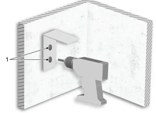
- Fasten holders to drilled holes in the wall, and fasten the satellite in the holder.
- Or
Fasten the satellite with a magnet.
Then an arrester loop must be attached.
For safety reasons, however, it is recommended for a permanent fastening with screws to be used. - Or
Clamp the satellite.
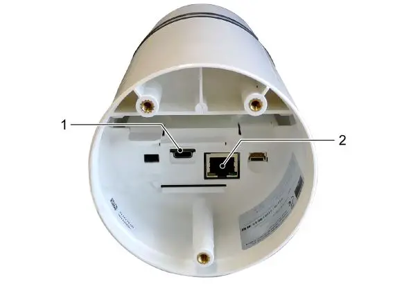
Integrate the satellite into the infrastructure- USB-C connection (power supply)
- Ethernet port (power supply and data transmission)

- Connect satellite via POE (RJ45) to the power supply and the network with the preinstalled industrial PC. An amplifier must be used if the cable is 100 m long or more. The light ring of the satellite must respond.
or- In exceptional cases after consultation with TRUMPF: Connect satellite via USB-C with the power supply.
The satellite is automatically switched on as soon as it is connected to the mains.
- In exceptional cases after consultation with TRUMPF: Connect satellite via USB-C with the power supply.
Start-up of preinstalled industrial PC
Conditions
One of the following browsers is available: Google Chrome, Mozilla Firefox, Windows Edge, Apple Safari. A browser-enabled company PC with RJ45 input and an Ethernet cable with RJ45 plugs are available. For operation, some ports and URLs are necessary which must be enabled or whitelisted in the firewall, filter or proxy appliance.
- eco.tnt.api.trumpf.com:443 (TCP)
- a31usskdgfoiwa-ats.iot.eu-central-1.amazonaws.com:443 (TCP)
- 5k8ygulic6.execute-api.eu-central-1.amazonaws.com:443 (TCP)
- trumpf.jfrog.io:8081 (TCP)
- gitlab.com/TRUMPF-corp/locationTrackingSytem/Development:443 (TCP)
- 185.82.160.50 or tpp-de.tnt.api.trumpf.com
- 185.82.163.20 or tpp-sg.tnt.api.trumpf.com
- 218.4.161.131 or tpp-cn.tnt.api.trumpf.com
- The ports 500 (UDP), 4500 (UDP) and 443 (TCP)
- tnt-devops-puppet-server-xe5nibbltusunrkr.eu-central-1.opsworks-cm.io
- The ports 8140, 8142 and 61613 (all TCP)
- DNS (port 53, TCP and UDP) and NTP (port 123, UDP) must function.
- The computer should be placed in an easily accessible location.
Connect preinstalled industrial PC
- Connection to customer’s network
- Satellite network connection
- Start-up of the service port
- Power supply
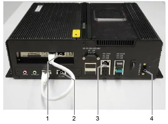
For the satellite network, all Ethernet cables of the satellites are connected via a separate PoE switch, and the PoE switch is connected to the preinstalled industrial PC via port (2). Explanation of the individual connections: - WAN1 (mGuard card)
Local network and Internet connectivity to provide the web application in the LAN. Upgrades and security updates are installed, the service is monitored and errors are corrected via the Internet connection. - LAN4 – Looping back to mGuard card Is provided with a red, secured patch cable during start-up.
- LAN3 For connection to the satellite network.
- LAN1 and LAN2 Service or debugging ports for local error identification.
If the local network connection of the preinstalled industrial PC is lost, a PC or laptop can be connected to the network via this connection (subnet 172.30.0.0, DHCP must be activated on the device). Address 172.30.0.1 in the browser provides access to the Setup/Network wizard for troubleshooting connection problems.
- Connect a PoE-capable switch to the pre-installed industrial PC (2).
- Connect all satellites to the switch.
- Connect the preinstalled industrial PC to the Internet (1).
- Plug in power supply (4).
The computer switches on automatically.
The light band on the satellite lights up white. This may take some minutes.
If the light band lights up blue, the satellite is currently
dialing into the network, if it lights up red, there is no network connection yet. - All further commissioning steps will be carried out on the commissioning date.


