EPEVER MT91 Inverter Remote Meter User Manual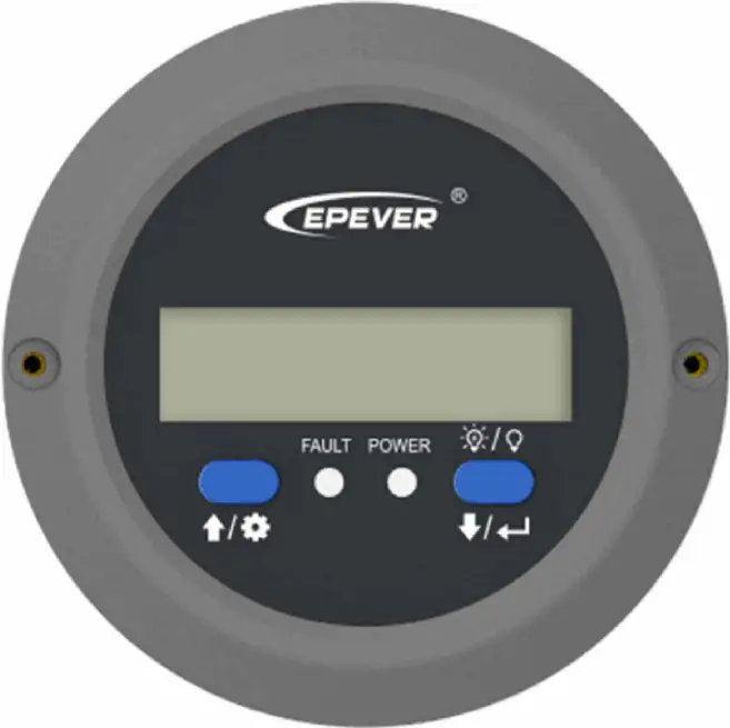
Safety Instructions
- Thanks for selecting the MT series; please read this manual carefully before using the product.
- Please keep this manual for future reference.
- When you receive the product, check whether there is any damage that occurred in transportation. Contact the transportation company or our company in time for any problem.
- Please read this manual and safety information carefully before installing it.
- Keep the product away from rain, exposure, severe dust, vibration, corrosion, and intense electromagnetic interference.
- Please avoid water, and other liquids enter into the product.
- There are no user-serviceable parts inside the product. Do not disassemble or attempt to repair it.
Overview
MT91 is a new generation of remote meters specially designed for the EPEVER inverters. It displays the real-time parameter of the inverter on one screen. Supporting parameter configuration by the button operations, which makes the product suitable for different requirements.
Features
- Dual interface design, friendly connection with the EPEVER inverter and other optional modules
- LCD screen, real-time dynamic display of system data
- Visually error codes, timely notification of warnings and faults
- Load ON/OFF button to control the load output directly
- Simple installation and friendly operation interface
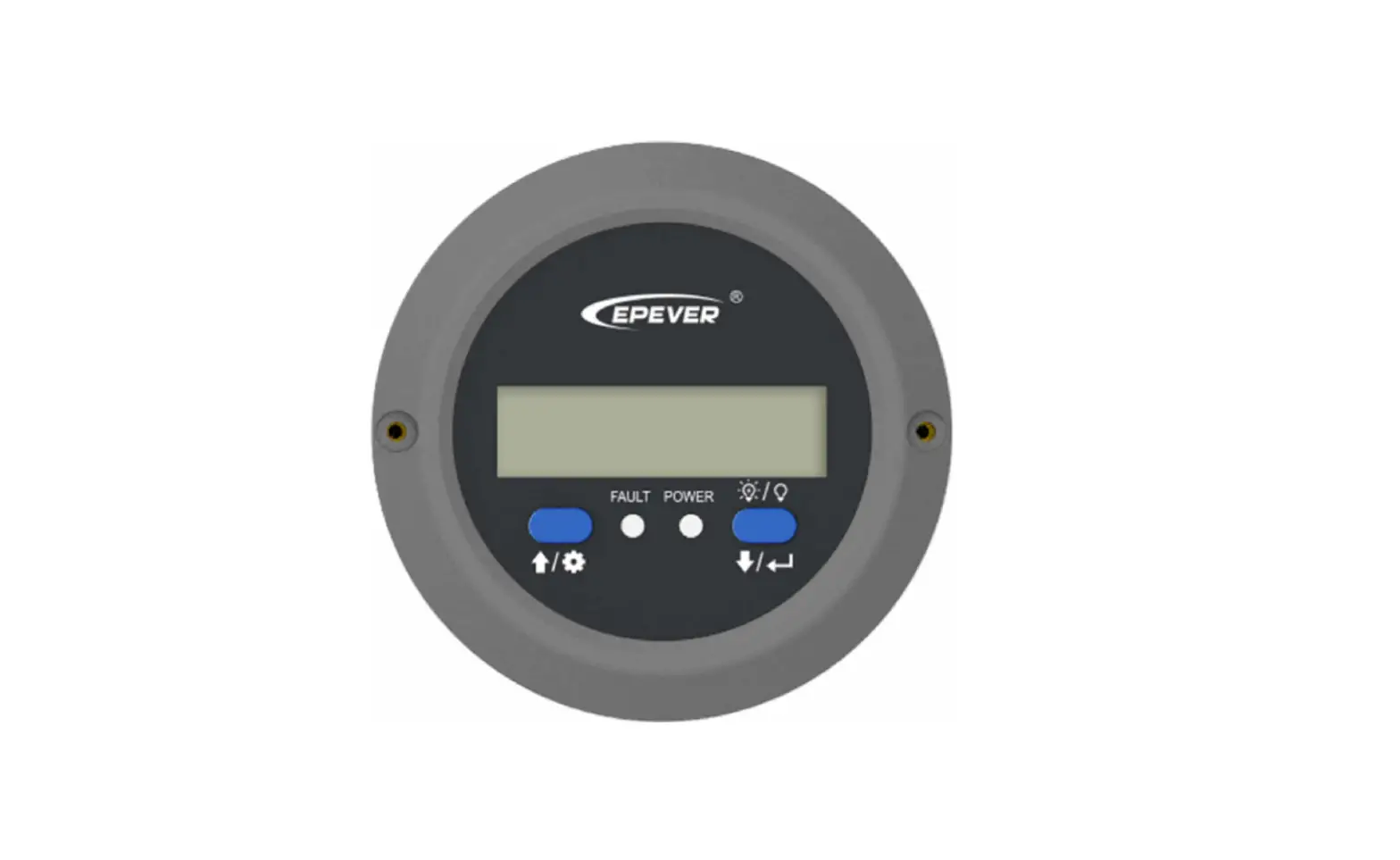
Appearance
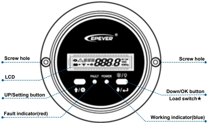
In the real-time interface, long press for 2 seconds to turn off the load(default on); long-press it again for 2 seconds to turn on the load.
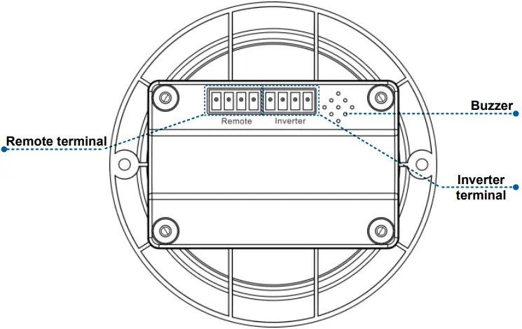
Definition of the inverter terminal/remote terminal:
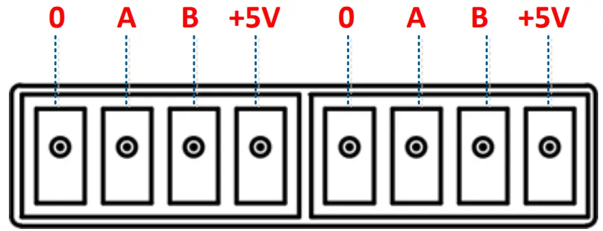
- Connect the MT91 with an inverter:
Connect the MT91’s “inverter terminal” and the inverter’s RJ45 port through an RS485 communication cable (included accessory, model: CCRJ45 3.81-100U. The cable length can be customized according to customers’ actual requirement.) - Connect the MT91 with an auxiliary module
Connect the “remote terminal” of the MT91 and the auxiliary modules such as the Bluetooth module/wireless module/BMS through an adapter cable.
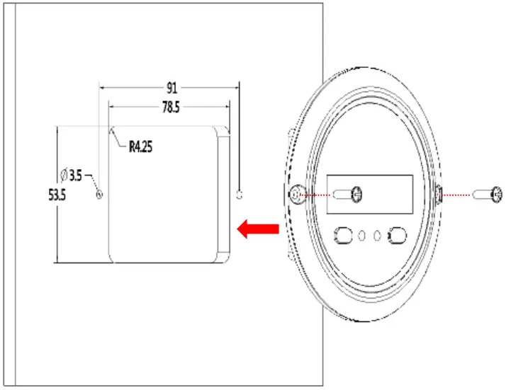
Installation Instructions
Surface mounting installation is recommended.
Step 1: Locate based on the installation size (91mm) and drill two screw holes (no smaller than 77x52mm).
Step 2: Use two PWM3*10 screws to fix the remote meter.
| Button | Operation | Instruction |
 | Click | Move up/parameter increase |
Press for 2s | Ÿ In the real-time interface (that is, the default interface after the device is powered on), press it for 2s to enter the setting interface.Ÿ In the setting interface, press it for 2s to enter the specific parameter configuration interface. | |
 | Click | Move down/parameter decrease |
Press for 2s | Ÿ In the real-time interface, press it for 2s to turn on/off the load output (default on, press it for 2s to turn off the load output).Ÿ In the setting interface, press it for 2s to confirm the parameter configuration. | |
 | Click | In the setting interface, click them toexit the parameter configuration interface. |
| Press for 2s | In the real-time interface, press them for 2s to clear the faults. |
Real-time Interface
In the real-time interface(namely, the default interface after the device is powered on), please click or to display the below parameters in a cycle.
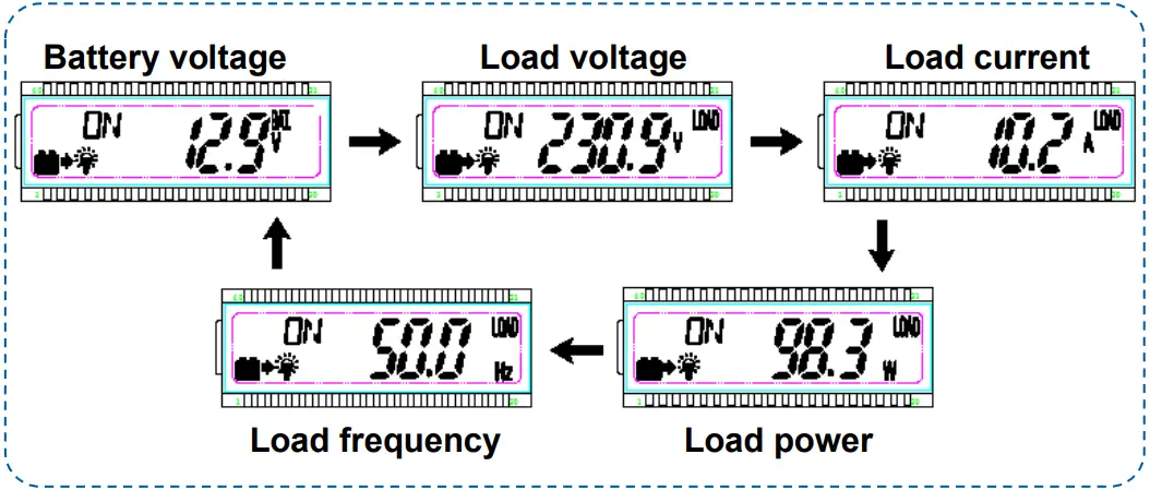
Note: means the load being ON status, means the load being OFF status.
Setting Interface
Parameter configuration
Step1: In the real-time interface, press for 2s to enter the parameter setting interface.
Step2: Click or to select the parameter to be configured.
Step3: Press for 2s to enter the configuration interface of the specified parameter. The parameter value will be flashing.
Step4: click or to configure the parameter value.
Step5: Press for 2s to confirm the configuration.
Step6: Click + to exit the current interface.
Power Saving Mode
Users can enable the power saving mode and set the PSI/PSO value by the / button (The minimum power step is 1VA).
When the actual load power is lower than the PSI (the power to enter the power saving mode), the system will automatically switch to the power saving mode, and then the device output is turned on for 1s and turned off for 5s. When the actual load power exceeds the PSO (the power to exit the power saving mode), the inverter will automatically exit the power saving mode and resume work.
Enable power saving mode (PSE)
Step1: In the real-time interface of the remote meter, press and hold the button to enter the parameters setting interface.
Step2: Click the or button to select the PSE parameter.
Step3: Press and hold the button until the PSE parameter (OFF default) flashes.
Step4: Click the or button to set the PSE status.
- Select ON to enable the power saving mode.
- Select OFF to disable the power saving mode.
Step5: Press and hold the button to confirm.
2) Set the power to enter the power saving mode (PSI)
Step6: In the parameters setting interface, click the or button to select the PSI parameter.
Step7: Press and hold the button until the PSI value flashes.
Step8: Click the or button to set the PSI parameter.
3) Set the power to exit the power saving mode (PSO)
Step10: In the parameters setting interface, click the or button to select the PSO parameter.
Step11: Press and hold the button until the PSO value flashes.
Step12: Click the or button to set the PSO parameter
Parameters user define
| Display | Parameters | Default | User define |
| VPT | Output voltage class① | 220VAC | 220VAC/230VAC/240VAC |
| 110VAC | 100VAC/110VAC/120VAC | ||
| FRE | Output frequency class① | 50Hz | 50Hz/60Hz |
| BLT | LCD backlight time | 30s | 30s/ 60s/100s(ON solid) |
| PSE | Power Saving Enable | OFF | ON/OFF |
| PSI | Power Saving In | 20VA | 20VA ~ (20%*rated power) |
| PSO | Power Saving Out | 40VA | (20VA + PSI) ~(50%*rated power) |
| ERS | Baud Rate Select | 115200 | 9600/115200 |
| LVD | Low voltage disconnect voltage② | 12V: 10.8V24V: 21.6V48V: 43.2V | 12V: 10.5V~14.2V; stepsize 0.1V24V: 21V-30.2V; step size 0.1V48V: 42V-62.4V; step size0.1V |
| LVR | Low voltage reconnect voltage② | 12V: 12.5V24V: 25V48V: 50V | 12V: 11.5V~15.2V; stepsize 0.1V24V: 22V-31.2V; step size 0.1V48V: 43V-63.4V; step size0.1V |
| OVR | Over voltage reconnect voltage② | 12V: 14.5V24V: 29V48V: 58V | 12V: 11.5V~15.2V; stepsize 0.1V24V: 22V-31.2V; step size 0.1V48V: 43V-63.4V; step size0.1V |
| OVD | Over voltage disconnect voltage② | 12V: 16V24V: 32V48V: 64V | 12V: 12.5V~16.2V; stepsize 0.1V24V: 23V-32.2V; step size |
- After configuring the parameters marked with ①, the inverter will restart automatically. It will resume work according to the new parameter value.
- NPower and IPower-Plus series support the modification of parameters marked with②. Please refer to the following rules for the modification; otherwise, the parameter setting will not succeed. IPower does not support modification of parameters marked with②.
Rules for battery protection voltage
A. Over voltage limiting voltage(16.2/32.2/64.4V) ≥ Over voltage disconnect voltage ≥ Over voltage reconnect voltage +1V.
B. Over voltage reconnect voltage ≥ Low voltage reconnect voltage.
C. Low voltage reconnect voltage ≥ Low voltage disconnect voltage +1V.
D. Low voltage disconnect voltage ≥ Low voltage limiting voltage(10.5/21/42V).
Detail status is shown as the following when reaching the protection voltage point.
| Input voltageprotection | Status |
| Over voltage protection | The output is switched OFF. The blue indicator fast flashes.Buzzer beeps.LCD displays the . |
| Over voltage reconnect | The blue indicator is ON solid. The output voltage is normal. |
| Low voltage protection | The output is switched OFF. The blue indicator slowly flashes.Buzzer beeps.LCD displays the . |
| Low voltage reconnect | The blue indicator is ON solid. The output voltage is normal. |
Note: Although the inverter is designed with the over voltage protection function, the surge voltage is not higher than 20V for the 12V system, not higher than 40V for the 24V system, and not higher than 80V for the 48V system; otherwise, the inverter may be damaged.
Error Codes
| Error code | Faults | Buzzer | Working indicator | Fault indicator |
| OTP | Inverter over temperature Heat sink over temperature | 5 beeps | OFF | ON solid |
| IOV | Input over voltage | 5 beeps | Fast flashing (1Hz) | OFF |
| ILV | Input low voltage | 5 beeps | Slowly flashing(1/4Hz) | OFF |
| OSC | Output short circuit | 5 beeps | OFF | Fastflashing (1Hz) |
| OOL | Output overload | 5 beeps | ON solid | Slowly flashing (1/4Hz) |
| OVA | Output voltage abnormal | 5 beeps | OFF | OFF |
Specifications
| Model | MT91 |
| Compatible products | IPower-Plus, IPower/NPower① |
| Power supply | 5VDC |
| Power supply method | Inverter communication port |
| LCD visual angle | 12′ clock |
| LCD backlight | Yes |
| Installation method | Surface mounting installation |
| Self-consumption | 14mA/5V(no backlight)23mA/5V(backlight) |
| Environment temperature | -20℃~+60℃ |
| Storage temperature | -35℃~+70℃ |
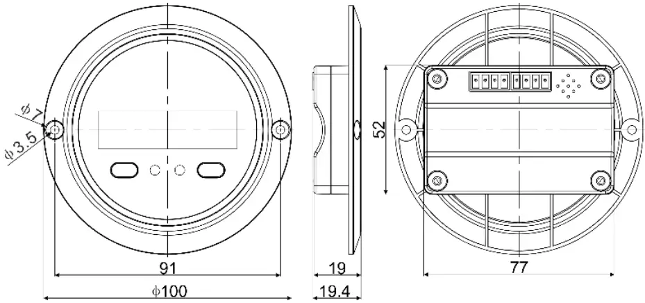
| Dimension | 100 x 19.4mm |
| Mounting size | 100 x 50mm |
| Mounting hole size | Φ3.5mm |
| Net Weight | 65g |
IPower-Plus supports MT91 whole functions, while IPower/NPower supports part MT91 functions; for detail supported functions, refer to user manual.
Dimension
HUIZHOU EPEVER TECHNOLOGY CO., LTD.
Beijing Tel: +86-10-82894896/82894112
Huizhou Tel: +86-752-3889706
E-mail: [email protected]
Website: www.epever.com


