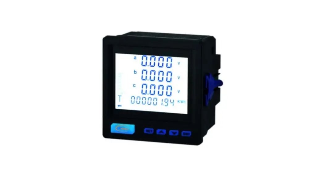
![]() MT-DP96HMF Digital Multifunction Meter
MT-DP96HMF Digital Multifunction Meter
User Manual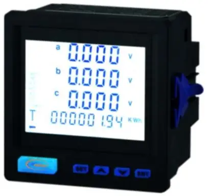
MT-DP96HMF Digital Multifunction Meter
Thanks for choosing our product – MT-DP96HMF, Please read this manual carefully and pay attention to below caution matters.
CAUTION![]() This product should be installed and maintained by professional person
This product should be installed and maintained by professional person![]() Before operating this product inside or outside, please cut off the input signal and power supply;
Before operating this product inside or outside, please cut off the input signal and power supply;![]() Please make sure all parts of the product don’t have voltage by suitable voltage detection device
Please make sure all parts of the product don’t have voltage by suitable voltage detection device![]() The power supply should be within the rated range
The power supply should be within the rated range
The below situation will result in device damage and abnormal working![]() Auxiliary power source voltage over range
Auxiliary power source voltage over range![]() Distribute system frequency over range
Distribute system frequency over range![]() Current, voltage input polarity incorrect
Current, voltage input polarity incorrect![]() Disconnect the communication plug under charged situation
Disconnect the communication plug under charged situation![]() No according requirement to connect terminal
No according requirement to connect terminal![]() Please don’t touch the terminals when the meter is in operation!
Please don’t touch the terminals when the meter is in operation!
Function introduce
| Measure function | Remark | |
| Realtime measure | Three phase voltage (L-L, L-N) | Basic function/ |
| Three phase current and neutral current | ||
| System Frequency | ||
| P, Q, S, PF (per phase & total | ||
| Electric energry | KWh import | |
| KVARh import | ||
| KWh export, KVARh export | ||
| Harmonics | THDU per phase | |
| THDI per phase | ||
| HDI per phase from 2nd to 31st order | ||
| HDU per phase from 2nd to 31st order | ||
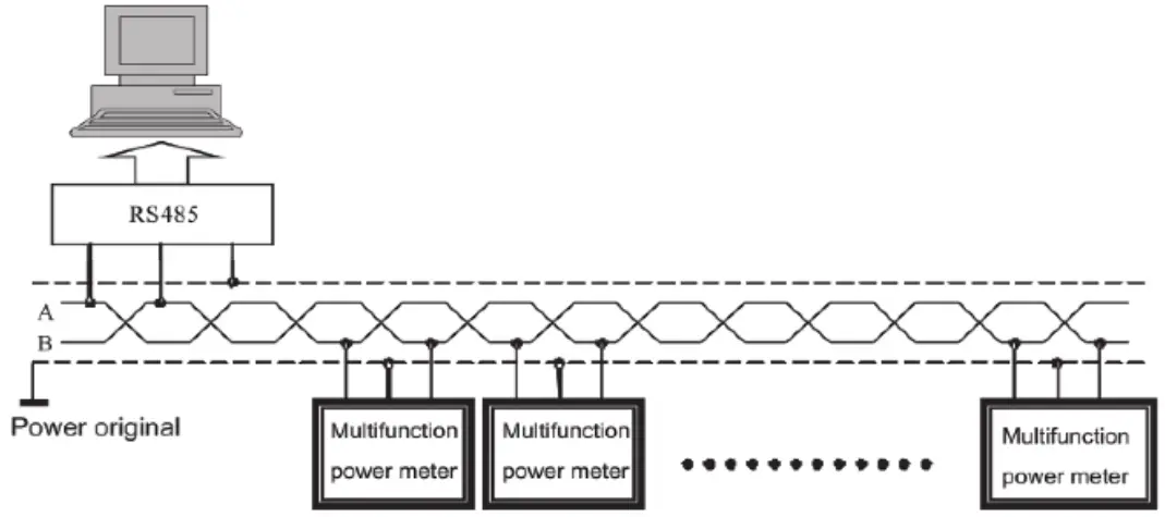
| Communication | RS485 Port MODBUS-RTU | |
| Maximum Demand/ | U,I,P,Q | Expand option/ |
| Analog output/ | 0-20mA/ 4-20mA/ 0-5V/ 0-10V | |
| Digital input/ | Dry contact type/ | |
| Relay output/ | AC250V 5A Remote/ Alarm | |
| Display type/ | LCD | |
Technical parameter
| Parameter | |||
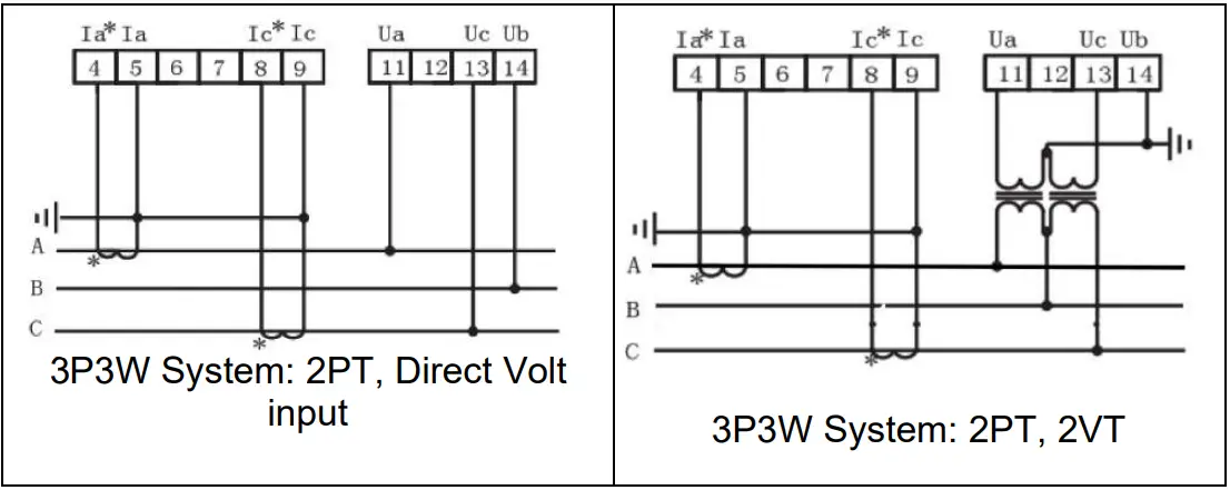
| Signal Input/ | Connection system | 3P3W/ 3P4W | |
| Voltage | Measurement range | 519V L-L | |
| Over load | Continuous: 1.2 Vn; Instantaneous: 2Vn | ||
| Power consumption | < 1VA | ||
| Current | Measurement range | 5A/ 1A | |
| Over load | Continous: 1.2In; Instantaneous: 2In | ||
| Power consumption | < 1VA | ||
| Frequency | 45 – 65Hz | ||
| Auxiliary power supply | AC85-265V DC100-300V | ||
| Communication | RS485 communication port, physical layer isolation. According international standard MODBUS-RTU agreement. Communication speed 1200-38400 (Default 9600) Test type N81, E81, 081 (Default N81) | ||
| Analog output | 0-20mA/ 4-20mA/ 0-5V/ 0-10V | ||
| Relay output | Programme remote/ Alarm switching output Capacity 5A at 250VAC/ 30VDC | ||
| Digital input | Remote switch input signal, dry contact input. Program relate alarm output |
| Measure class | Current, Voltage, Active power, Energy: 0.5S; Reactive power: 1S; Frequency: ±0.1Hz |
| IP protection | IP53 for indoor type and PI65 for outdoor type |
| Environment | Working temperature: -10÷55°C Store temperature: -20÷75°C Relative Humidity:<80%RH |
| Safe | Isolation: Signal, auxiliary power supply, output terminal crust resistance >5MW and withstand voltage pulse >AC2KV |
Installation and correction
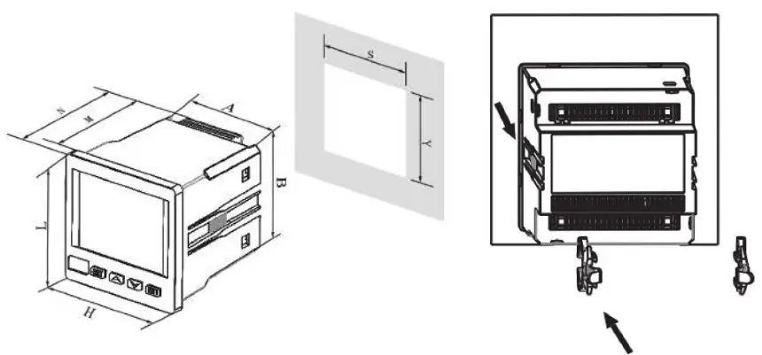
| LxH (mm) | AxB (mm) | SxY (mm) | SxY (mm) IP65 | N (mm) | M (mm) |
| 96×96 | 90.5×90.5 | 91×91 | 91.5×91.5 | 94 | 88 |
| Active Pulse | Reactive Pulse | RS485 | Aux. Power Suply | ||||||
| Ep- | Ep+ | Ep- | Ep+ | B | A | N(V-) | L(V+) | ||
| 48 | 47 | 50 | 49 | 59 | 58 | 2 | 1 | ||
| Relay Output | Digital input | Analog output | |||||||||||||||
| DO1 | DO2 | DO3 | DO4 | COM | DI1 | DI2 | DI3 | DI4 | A0- | A01+ | A02+ | A03+ | A04+ | ||||
| 15 | 16 | 17 | 18 | 19 | 20 | 21 | 22 | 70 | 71 | 72 | 73 | 74 | 30 | 31 | 32 | 33 | 34 |
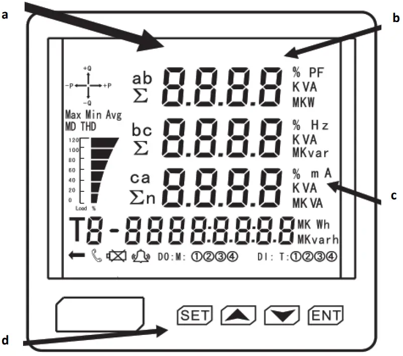
a. Four lines digital display measure information: Three phase voltage, three phase current, active power, reactive power, power factor, frequency, switch input, output, other switch input, two way active power, two way reactive power, analog input, demand
b. K is light mean practice value is display value is 1.000 times. M is light mean practice value is display value is 1.000.000 times
c. Measure item unit or characteristic: three phase voltage V, three phase current A, active power W, reactive power VAR…
d. Buttons use in change or programme set:
| is change page button or value increase or decrease button | |
| is enter programme status | |
| is select confirm button |
If there is no relative symbol display or the set data not working, It means the product without the relative function
| Board | Content | Explain |
| DISP=1 -Three phase voltage -Forward active energy Kwh | 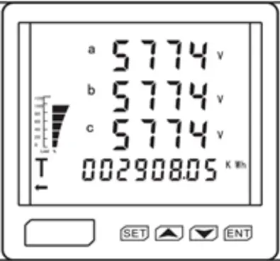 | Separate display voltage Ua, Ub, Uc (in the 3P4W) In left fig. Ua=5774V Ub=5774V Uc=5774V Forward active energy = 2908.05KWh |
| DISP=2 -Three phase voltage -Reverse active energy Kwh | 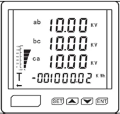 | Separate display voltage Uab, Ubc, Uca (in the 3P4W) In left fig. Uab=10KV Ubc=10KV Uac=10KV Reverse active energy =1000.02 Kwh |
| DISP=3 -Three phase current -Forward reactive energy Kvarh | 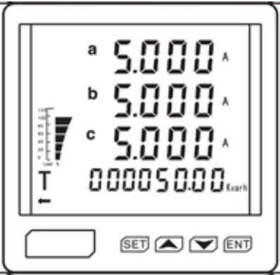 | Separate display current la, lb, lc (in the 3P4W) In left fig. la=5A Ib=5A Ic=5A Reverse reactive energy = 50 Kvarh |
| DISP=4 -Total active power -Total reactive power -Total apparent power | 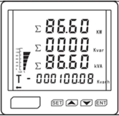 | Total active power = 86.6KW Total reactive power = 0000Kvar Total apparent power =86.6KVA Reverse reactive energy =100.08Kvarh |
| DISP=5 – Active power phase A -Reactive power phase A -Apparent power phase A | 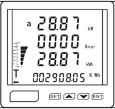 | Active power of phase A = 28.87KW Reactive power of phase A = 0000Kvar Apparent power of phase A =28.87KVA Forward active energy =2908.05KWh |
| DISP=6 – Active power phase B -Reactive power phase B -Apparent power phase B | 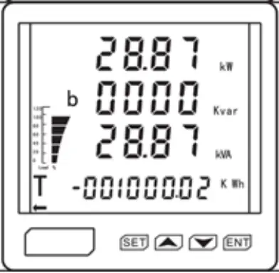 | Active power of phase B = 28.87KW Reactive power of phase B = 0000Kvar Apparent power of phase B =28.87KVA Reverse active energy =1000.02KWh |
| DISP=7 – Active power phase C -Reactive power phase C -Apparent power phase C | 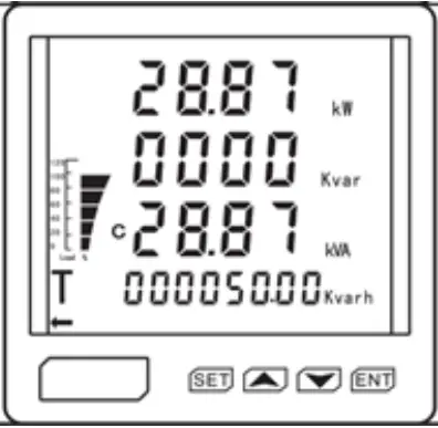 | Active power of phase C = 28.87KW Reactive power of phase C = 0000Kvar Apparent power of phaseCB =28.87KVA Forward reactive energy =50.00KVARh |
| DISP=8 – Average current -Zero sequence current | 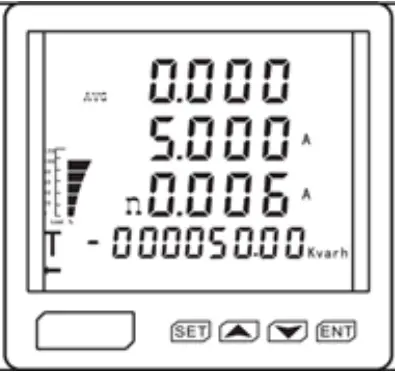 | Average current = 5A Zero sequence current = 0.06A Reverse reactive energy =50.00KVARh |
| DISP=9 – Three phase total power factor -Frequency -Voltage unbalance | 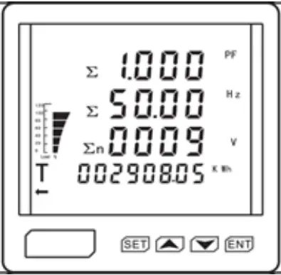 | Three phase total power factor =1.000 Frequency = 50Hz Voltage unbalances = 9V Forward active energy =2908.05KWh |
| DISP=10 Split phase power factor | 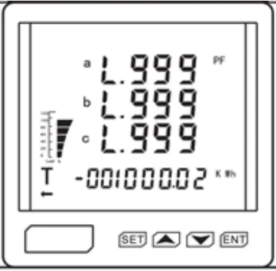 | Power factor of phase A =0.999 (inductive load) Power factor of phase B =0.999 (inductive load) Power factor of phase C =0.999 (inductive load) Reverse active energy =1000.02KWh |
| DISP=11 Total voltage harmonic | 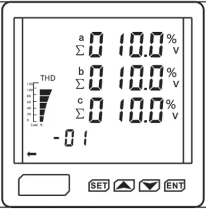 | In the left fig: a.b.c phase total voltage harmonic =10% |
| DISP=12 2nd voltage harmonic | 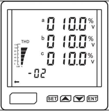 | In the left fig: 2nd voltage harmonic of a.b.c phase =10% |
| DISP= 41 31st voltage harmonic | 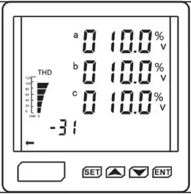 | In the left fig: 31st voltage harmonic of a, b. c phase =10% |
| DISP=42 Total current harmonic | 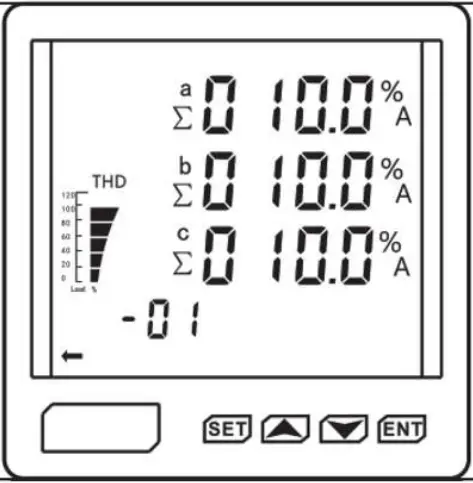 | In the left fig: a.b.c phase total current harmonic =10% |
| DISP =43 2nd current harmonic | 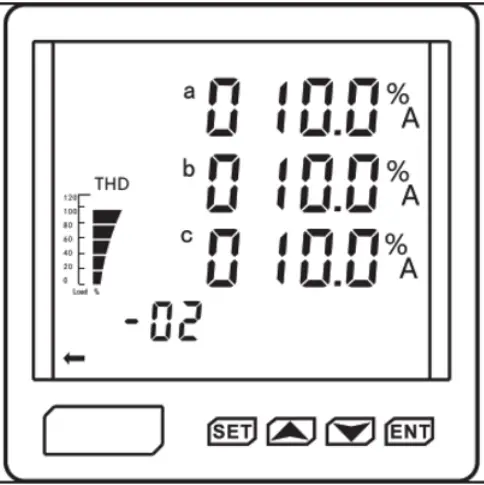 | In the left fig: 2nd current harmonic of a, b, c phase =10% |
| DISP= 72 31st current harmonic | 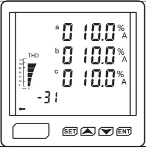 | In the left fig: 31st current harmonic of a, b,c phase =10% |
| DISP=73 Residue current | 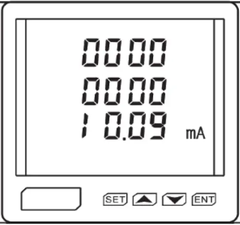 | In left fig. display Residual current value: 10.09mA |
| DISP=74 Digital input information from 1 to 12 way channel | 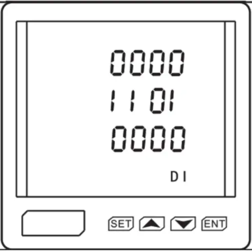 | First line: 1-4 way channel Second line: 5-8 way channel Third line: 9-12 way channel In left fig.: No.5 way, No.6 way, No.8 way Chanel are ON,other way Chanel is OFF |
| DISP=75 Digital output information from 1 to 4 way channel | 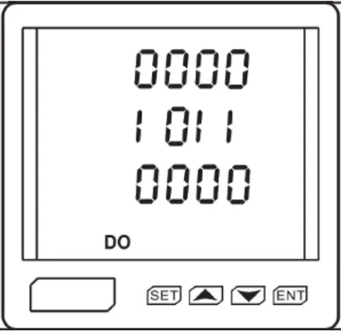 | In left fig.: No.1 way, No.3 way, No.4 way Chanel are ON, No.2 way Chanel is OFF |
Programme operation
In programme status, digital interface adopt layers structure menu type, meter supply three lines number display (se fig. 5)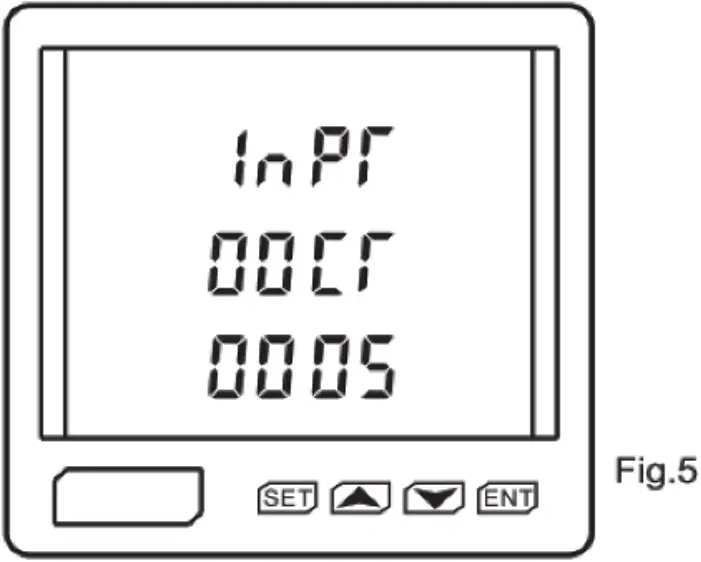 No.1 line is first layer menu information;
No.2 line is second layer menu information;
No.3 line is third layer menu information;
Exp: The fig.5 shown: No.1 layer: INPT = Signal input; No.2 layer: CT = current transformer; No.3 layer: current value is 5, It means ratio of CT is 25/5A.
The digital display interface menu has the following organizational structure, the user can choose the appropriate setting parameters according tho the actual situation.
| No.1 Layer | No.2 Layer | No.3 Layer | Description |
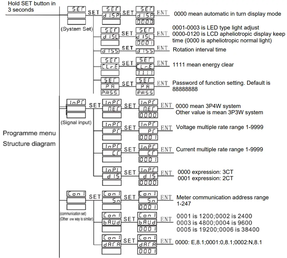
| System SET | Display DISP | 0000-0017 | 0000 mean automatic cycling display. Each board connect see table 6 |
| DISL | 0001-0003 or 0000-0120 | 0000-0120 is keening time of LCD back light. 0000 means the backlight keeping ON | |
| Data clear CL r. E | 1111 | 1111 means the data clear other value is invalid |
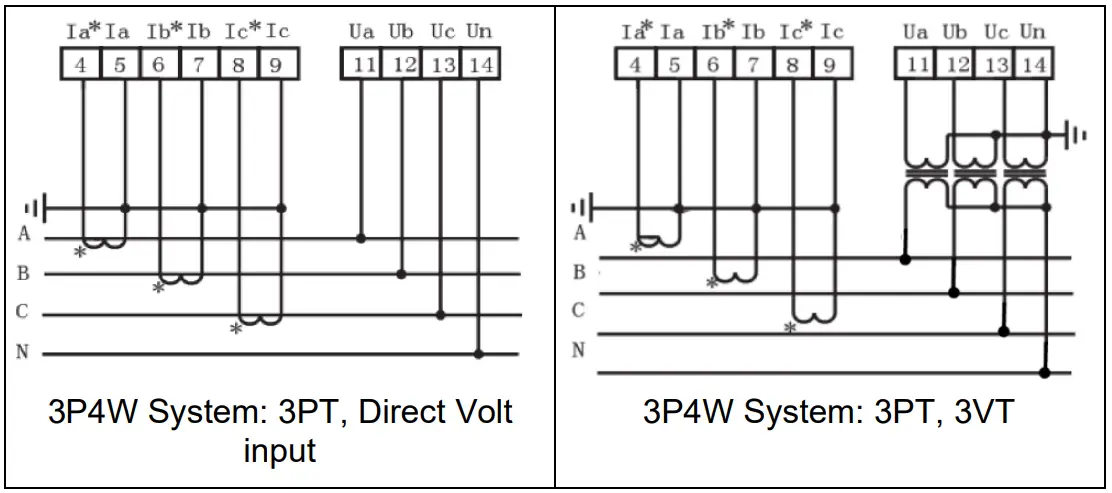
| Signal Input INPT | Wiring type Net | 0000 or other value | 0000 mean 3P4W system. Other value is mean 3P3W system |
| Voltage trans. ratio PT | 1 ∼ 9999 | PT value= PT primary value/ secondary value | |
| Current trans. rato PT | 1 ∼ 9999 | CT value= CT primary value/ secondary value |
| Communication Set CON i (i is 1 ∼ 2) | Address SN | 1 ∼ 247 | Meter address range 1 to 247 |
| Communication speed BAUD | 0001 ∼ 0004 | 0001 is 1200; 0002 is 2400; 0003 is 4800; 0004 is 9600; 00005 is 9200; 00006 is 38400 | |
| Data format DATA | 0001 ∼ 0003 | 0000 is E,8, 1; 0001 is 0,8,1; 00002 is N,8,1 |
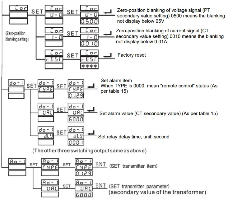
| Digital output Set DO- i (i is 1 ∼ 4) | Choose alarm item or close alarm | Set alarm item’s specific threshold value | Choose alarm item, and set relative threshold value (when alarm item is digital value, no need set threshold value), once meet alarm condition, switch output working |
| Analog output Set AO—i (i is 1 ∼ 4) | Chosen transmitter item or close analog output (refer to 8.2 analog output) | Set the full scale value of analog item | Choose transmitter item’s and relative electrical parameter (0-20mA, 4-20mA, 4-12-20mA) For example, set “A0-1″ TYPE”0135″ UAL”5000”, which means A phase current 0-5A corresponds to the transmitter output signal of first loop 4-20mA |
Note: The above menu is applied to the product with complete functions. If you find there is no such menu in the product or the menu is not working, It means the product not supporting the function.
 (Analog capacity output: other three ways is similar)
![]() Version 1.0
Version 1.0


