EPEVER MT75 Remote Control Monitor
Safety Instructions
- Please keep this manual for future reference.
- Please read this manual and safety information carefully before using the product.
- Keep the product away from rain, exposure, severe dust, vibration, corrosion, and intense electromagnetic interference.
- Please avoid water, and other liquids enter into the product.
- There are no user-serviceable parts inside the product. Do not disassemble or attempt to repair it.
Overview
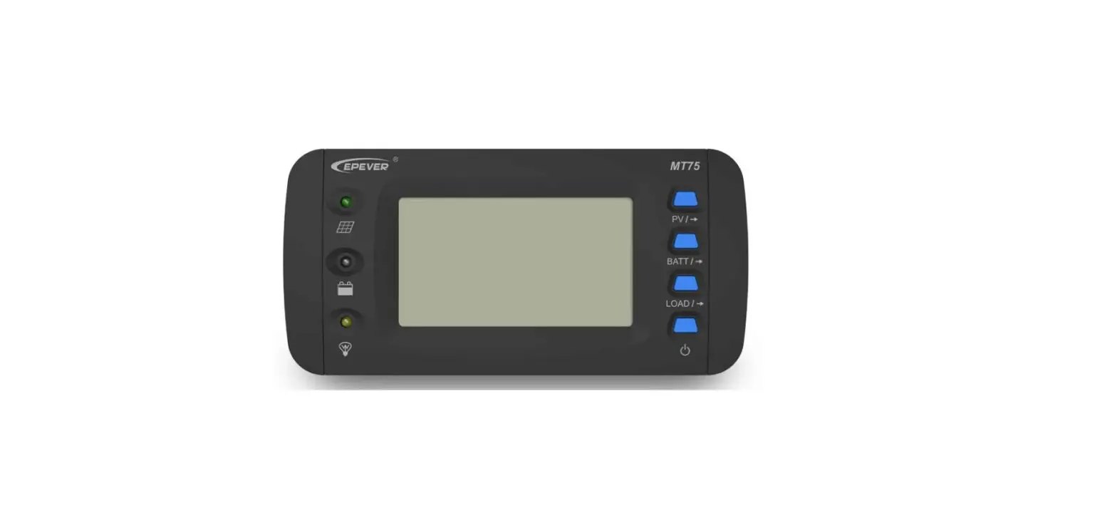
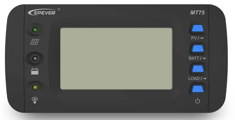
MT75 is a new generation of remote meters that can monitor the EPEVER solar charge controller and inverter on one screen simultaneously. This product provides multiple solutions to fit different requirements from off-grid users.
Features:
- Dual RJ45 communication ports
- 4.7-inch LCD screen, real-time dynamic display of system data
- Visually error codes, timely notification of warnings and faults
- Load ON/OFF button to control the load output directly
- Dry contact output and enable switch design
- Remote control inverter ON or OFF
- Friendly connect with different EPEVER devices
Appearance
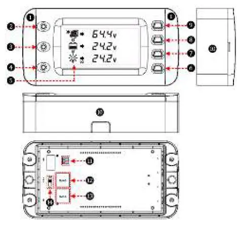
| ❶ | Decorative shell | ❽ | Battery parameter button |
| ❷ | PV indicator | ❾ | PV parameter button |
| ❸ | Battery indicator | ❿ | Base (optional) |
| ❹ | Load indicator | ⓫ | Dry contact interface① |
| ❺ | LCD | ⓬ | RS485 port 1(RJ45) |
| ❻ | Load ON/OFF button | ⓭ | RS485 port 2(RJ45) |
| ❼ | Load parameter button | ⓮ | Dry contact enable switch ① |
Working Principle: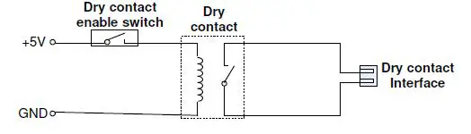
Dry contact rated value: 5A/30VDC; Max. value: 0.5A/60VDC Note: Turn the dry contact enable switch⓮ to ON only when the dry contact is used, and turn it OFF when not used to save the dry contact’s loss.
Accessories
| Category | Name | Number/Model | Purpose |
| Connect to the | |||
| 2P-3.81 plug | 2 pcs | 3.81 pins remote control switch of | |
| inverter | |||
| Included |
RS485 cable |
2 pcs/CC-RS485- RS485-200U | Connect the MT75 to the RJ45 port of the controller or |
| inverter | |||
| MT75 base | 1 pcs | Used for wall | |
| installation | |||
| CC-RS485- | Connect the MT75 to the RJ45 port of the controller or inverter | ||
| RS485- | |||
| RS485 cable | 50/100/200/300/50 0/1000U | ||
| (0.5/1/2/3/5/10 | |||
| meter) | |||
| USB cable | USB-RS485-200U | Connect the | |
| MT75 to the PC | |||
| Optional | Connect the MT75 to the | ||
| 3.81-RS485 cable | 3.81-RS485-200U | iTracer-AD series and the iTracer- | |
| ND series | |||
| controllers | |||
| C-2P3.81-2P3.81- | |||
| Dry contact interface cable | 50/100/200/300/50 0/1000U (0.5/1/2/3/5/10 | Connect the 3.81 plug | |
| meter) |
Installation Instructions
Before Installation
- Check whether the solar controller’s ID is 1; if not, set it to 1.
- Check whether the ID of the inverter is 3; if not, please set it to 3.
- Wall installation or surface mounting installation is optional.
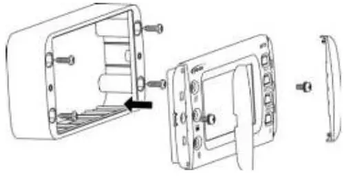
Wall Installation
- Step 1: Locate and drill screw holes based on the frame mounting dimension (175x50mm), and erect the plastic expansion bolts.
- Step 2: Use four M5 self-tapping screws to fix the frame.
- Step 3: Remove the decorative shell.
- Step 4: Use two M4 pan head screws to mount the MT75 surface on the base.
- Step 5: Install the decorative shell.

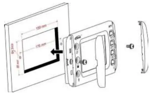
Surface Mounting Installation
- Step 1: Locate based on the installation size (176mm) and drill screw holes (no smaller than 158.2×85.2mm).
- Step 2: Remove the decorative shell.
- Step 3: Use two M4 pan head screws to fix MT75.
- Step 4: Install the decorative shell.

Indicator Instruction
| Indicator | Color | Status | Instruction |
|
| Green | ON solid | PV is charging |
| Green | OFF | No PV charge | |
| Green | Fast flashing | PV overvoltage | |
|
| Green | ON solid | Battery normal |
| Green | Fast flashing | Battery overvoltage | |
| Orange | ON solid | Battery under voltage | |
| Red | ON solid | Battery over-discharge | |
|
Red | Slow flashing | Battery over temperature Battery under temperature Controller over temperature | |
 | Green | ON solid | Load switch ON |
| Green | OFF | Load switch OFF | |
| Green | Fast flashing |
System voltage error |
| Orange | Fast flashing |
| Button | Operation | Instruction |
 | Click | Display PV parameters in cycle |
| Click | Display battery parameter in cycle |
| Click | Display load parameter in cycle |
| Exit the fault page | ||
| Press for 5S | Check error code information | |

| Click | Control the switch of solar controller and inverter in sync① |
|
Press for 5S | Clear the total of PV generated power, total DC load usage, and total AC load usage |
When the solar controller and inverter’s output is out of sync, click to turn off all the loads’ output simultaneously, click again to turn on all the load outputs.
LCD Display
LCD Display 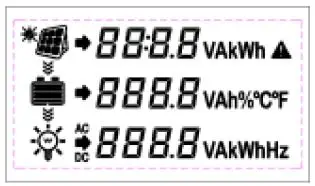
| Symbol | Definition | Symbol | Definition |
 | PV charging | PV no charge | |
| Load ON | Load OFF |
LCD Display Interface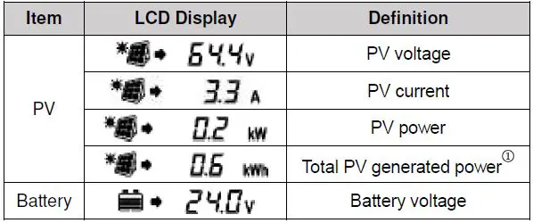
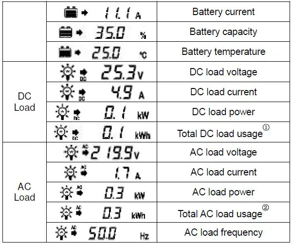
- The “Total PV generated power” and “Total DC load usage” is the solar controller’s parameter, which can be directly read and displayed by the MT75.
- The “Total AC load usage” is calculated based on the inverter’s AC load power and displayed on the MT75.
Error Codes
Solar Controller Error Codes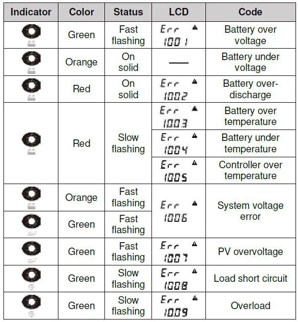
Note: When the battery voltage is equal to the low voltage disconnect voltage (LVD) point of the controller, the controller and inverter’s output will be turned off.
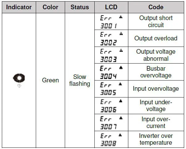
Inverter Error Codes
Specifications
| Model | MT75 | |
|
Compatible products |
Controller | XTRA-N series/TRIRON series/ Tracer-AN series/Tracer-BN series Note: Required cables for the above products are shipped with MT75. |
| iTracer-AD series/iTracer-ND series Note: Required cables for the above products need additional purchase. | ||
| Inverter | IPower series(1kw or above, suitable for application 1/3)/IPower-Plus series/ NPower series/SHI series | |
| Input power | 5VDC(Power supply by the connected controller or inverter) | |
| LCD visual angle | 12′ clock | |
| LCD backlight | Yes | |
| Installation methods | Wall installation Surface mounting installation | |
| Self- consumption | 14mA/5V(no backlight) 26mA/5V(backlight) | |
| Max. power consumption | 100mA/5V(Backligh+dry contact) | |
| Working temperature | -20℃~+65℃ |
| Storage temperature | -20℃~+80℃ |
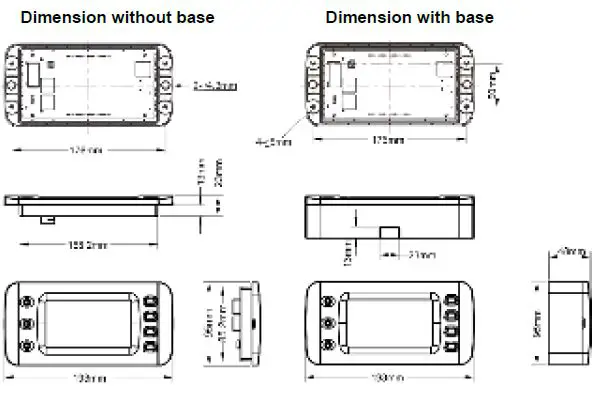
| Dimension | 193×95×48mm(base) 193×95×23mm(no base) |
| Mounting size | 175×50mm(base) 176mm(no base) |
| Mounting hole size | φ5mm(base) φ4.3mm(no base) |
| Net Weight | 0.29Kg(base) 0.22Kg(no base) |
Dimension
Recommended Applications
Standard Application
- Advantages
MT75 monitors the solar controller and inverter’s operational status while controlling the AC load and DC load output by the Load ON/OFF button directly. - Connection Diagram

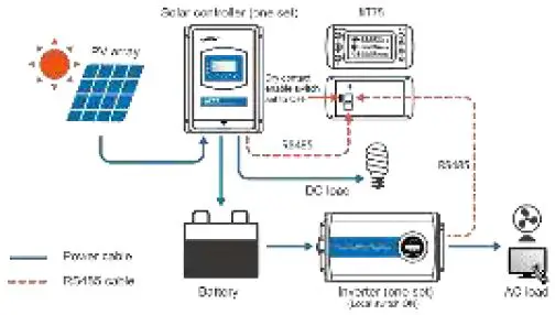
| No. | Item | Number |
| 1 | Solar controller | 1 pcs |
| 2 | Inverter | 1 pcs |
| 3 | MT75 | 1 pcs |
| 4 | RS485 cable(Included) | 2 pcs |
| 5 | PV, battery, AC load, DC load | According to actual needs |
Operations
- Connect the RS485 ports of MT75 to the controller and inverter.
- Set MT75’s dry contact enable switch to OFF state.
- Must set inverter switch to ON state.
- MT75 load ON/OFF button directly controls the AC and DC load output.
Upgrade Application
Advantages
MT75 monitors the operational status and error codes of the solar controller and inverter at the same time. The Load ON/OFF button controls the inverter start or stop, effectively reducing the inverter’s loss and extending the system’s lifetime.
Connection Diagram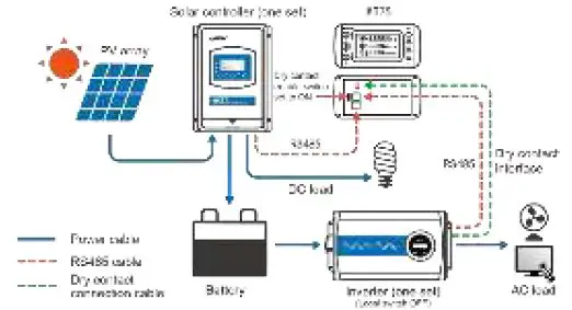
| No. | Item | Number |
| 1 | Solar controller | 1 pcs |
| 2 | Inverter | 1 pcs |
| 3 | MT75 | 1 pcs |
| 4 | RS485 cable(Included) | 2 pcs |
| 5 | Dry contact connection cable(Optional) | 1 pcs |
| 6 | PV, battery, AC load, DC load | According to actual needs |
- Connect the RS485 ports of MT75 to the controller and inverter.
- Connect the MT75’s dry contact interface to the inverter’s external switch port.
- Set MT75’s dry contact enable switch to ON state.
- Set inverter switch to OFF state.
- MT75 load ON/OFF button controls the inverter start or stop remotely.
Advanced Application
Advantages
With the RS485-1M2S module, the MT75 can monitor the operational status of the solar controller and inverter. Still, it also can connect with an external WIFI module, BT module, or USB cable. The phone APP or PC software can perform the parameter settings and operational status monitoring. MT75 can also control the output of AC and DC loads by the Load ON/OFF button.
Connection Diagram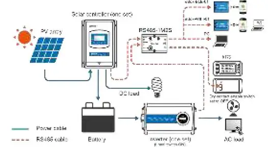
| No. | Item | Number |
| 1 | Solar controller | 1 pcs |
| 2 | Inverter | 1 pcs |
| 3 | MT75 | 1 pcs |
| 4 | RS485-1M2S module | 1 pcs |
| 5 | WIFI, BT module, or USB cable | 1 pcs |
| 6 | Mobile phone or PC | 1 pcs |
| 7 | RS485 cable | 4 pcs (2 pcs included, 2 pcs optional ) |
| 8 | PV, battery, AC load, DC load | According to actual needs |
Operations
- Connect the main port of RS485-1M2S to controller and inverter.
- Connect the slave port of RS485-1M2S to MT75 and WIFI module, BT module, or USB cable.
- Set MT75’s dry contact enable switch to OFF state.
- Must set inverter switch to ON state.
- Set the parameters or monitor the operational status by the phone APP or PC software.
- MT75 load ON/OFF button directly controls the AC and DC load output.
Pro. Application
Advantages
With the RS485-1M2S module, the MT75 can monitor the operational status of the solar controller and inverter. Still, it also can connect with an external WIFI module, BT module, or USB cable. The phone APP or PC software can perform the parameter settings and operational status monitoring. MT75 can also remotely control the inverter start or stop, which effectively prolongs the system’s lifetime.
Connection Diagram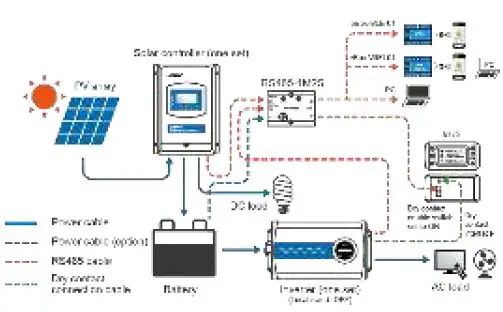
| No. | Item | Number |
| 1 | Solar controller | 1 pcs |
| 2 | Inverter | 1 pcs |
| 3 | MT75 | 1 pcs |
| 4 | RS485-1M2S module | 1 pcs |
| 5 | WIFI module, BT module, or USB cable | 1 pcs |
| 6 | Mobile phone or PC | 1 pcs |
| 7 | RS485 cable(Included) | 4 pcs (2 pcs included, 2 pcs optional ) |
| 8 | Dry contact connection cable(Optional) | 1 pcs |
| 9 | Power cable | 1 pcs |
| 10 | PV, battery, AC load, DC load | According to actual needs |
Operations
- Connect the main port of RS485-1M2S to controller and inverter.
- Connect the slave port of RS485-1M2S to MT75 and WIFI/BT/USB cable.
- Connect the MT75’s dry contact interface to the inverter’s external switch port.
- Set MT75’s dry contact enable switch to ON state.
- Set inverter switch to OFF state.
- Set the parameters or monitor the operational status by the phone APP or PC [email protected].
- MT75 load ON/OFF button controls inverter start or stop remotely.
HUIZHOU EPEVER TECHNOLOGY CO., LTD. Beijing
Tel: +86-10-82894896/82894112
Huizhou Tel: +86-752-3889706
E-mail: [email protected]
Website: www.epsolarpv.com


