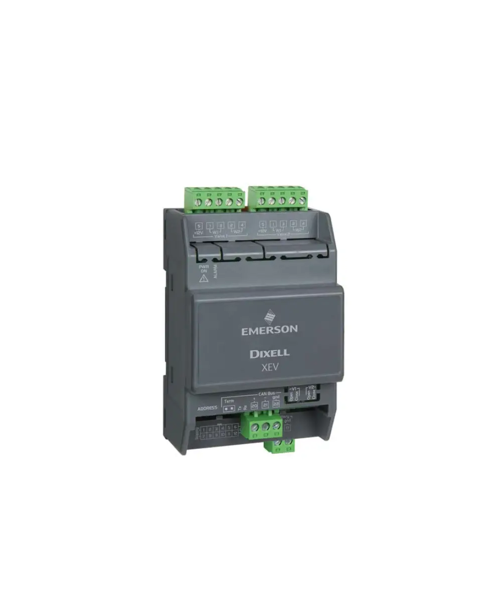
EMERSON XEV30K Stepper Valve Actuator

General Description
XEV30K is a stepper valve actuator intended either for bipolar stepper valves or unipolar stepper valves. This device has been used with iPro-Based case controllers.
The maximum configuration of hardware is equipped with:
- 3 configurable valve outputs to drive bipolar or unipolar valves.
- 6 Configurable analog inputs:
> Pb4/Pb5/Pb6: 4 to 20mA/0 to 5V/Pt1000; NTC/NTC_CPC
> Pb1/Pb2/Pb3: NTC/NTC_CPC/Pt1000 - LAN serial line to communicate with iPro series.
Absolute Maximum Power
XEV30K is able to drive a wide range of stepper valves. The following table contains the maximum values of current that the actuator can supply to the stepper wiring. Select the current transformer depending on the application using the following table: each kind of driving and functioning is reported that the Dixell transformer will use.
NOTE: The electrical power absorption of the valve can be unrelated to refrigeration power that valve has. Before using the actuator, please read the technical manual of the valve supplied by the manufacturer and check the maximum current used to drive the valve in order to verify that they are lower than those indicated below.
| CONFIGURATION | ||||
| ONE VALVE | TWO VALVES | THREE VALVES | ||
| Driving Mode | Full Step | Full Step | ||
| Valve Type | Bipolar Valves (4 wires) | Current 0.9A max >TF20D | Current 0.9A max for each valve > TF40D | Current 0.9A max for each valve >TF60D -TBC |
| Unipolar Valves (5-6 wires) | Current 0.33A max >TF20D | Current 0.33A max for each valve > TF20D | Current 0.33A max for each valve >TF40D-TBC | |
Wiring Diagram
Three Valve Configuration
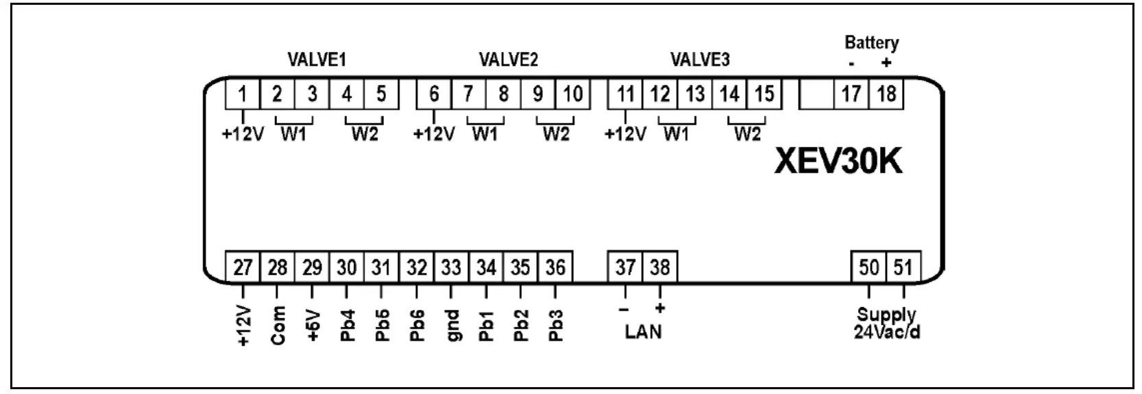
Valve Connections
Reference the following table to understand the connection mode for valves of different manufacturers.
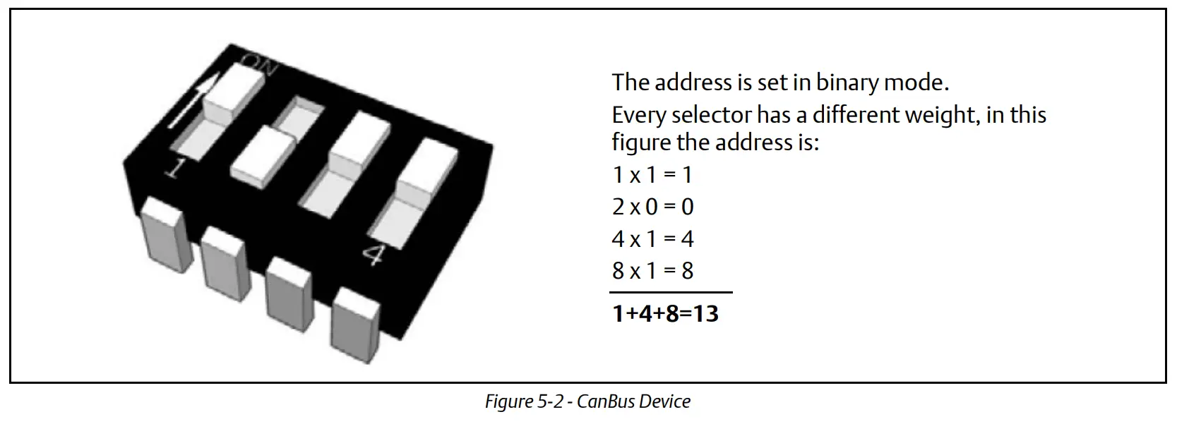
Serial Line – CanBus
The device can communicate through CanBus serial line only when a correct address is set. The addressing is made through the dip-switch called Address as demostrated in the following drawing: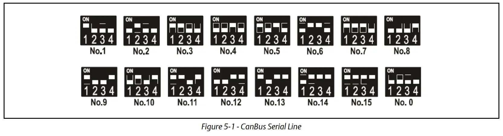
LEDs Meaning
Additional LED are added with the following functions, not reported on the wiring diagram.
| LED | MODE | MEANING |
| PWR ON | On | The device is correctly powered |
| ALARM | On | An alarm is present |
| TX/RX | Blinking | CanBus or LAN activity, communication activated |
| TX/RX | On | No link |
| OPEN V1 | Blinking | Valve 1 is opening |
| OPEN V1 | On | Valve 1 completely opened |
| CLOSE V1 | Blinking | Valve 1 is closing |
| CLOSE V1 | On | Valve 1 completely closed |
| OPEN V2 | Blinking | Valve 2 is opening |
| OPEN V2 | On | Valve 2 completely opened |
| CLOSE V2 | Blinking | Valve 2 is closing |
| CLOSE V2 | On | Valve 2 completely closed |
| OPEN V3 | Blinking | Valve 3 is opening |
| OPEN V3 | On | Valve 3 completely opened |
| CLOSE V3 | Blinking | Valve 3 is closing |
| CLOSE V3 | On | Valve 3 completely closed |
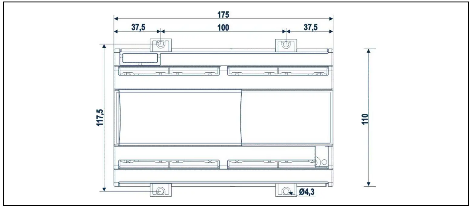
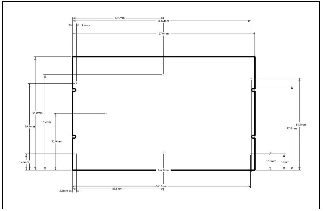
Dimensions
10 DIN Case – Dimensions
Open Board – Preliminary Dimensions
Technical Data
| Case | 10 DIN or open board |
| Connectors | Disconnectable terminal block ≤ 2,5 mm2 or screw connector |
| Power Supply | 24Vac/dc |
| Absorption | 60VA max |
| Probe Inputs | 3 configurable as NTC/NTC_CPC/Pt1000 3 configurable as NTC/NTC_CPC/Pt1000, 4 to 20mA/0 to 5V |
| Valve Output(s) | See table on page 2 |
| Serial Connection | LAN Bus |
| Data Storing | Non volatile memory (EEPROM) |
| Kind of Action | 1B; Pollution Grade: 2; Software Class: A |
| Rated Impulsive Voltage | 2500V; Over Voltage Category: II |
| Operating Temperature | –10 to 60 °C; Storage Temperature: -30 to 85 °C |
| Relative Humidity | 20 to 85% (no condensing) |
| Measuring and Regulation Range | NTC Probe: -40 to 110°C Pt1000 Probe: -50 to 100°C Pressure Transducer: -1.0 to 50.0 Bar |
| Resolution | 0,1°C or 1 °F; Accuracy@ 25°C: ±0,5 °C ±1 digit |
CUSTOMER SERVICES
Document Part # 026-4284 Rev 0
This document may be photocopied for personal use.
Visit our website at www.climate.emerson.com for the latest technical documentation and updates.
Join Emerson Technical Support on Facebook. http://on.fb.me/WUQRnt
For Technical Support call 833-409-7505 or email ColdChain.[email protected]
The contents of this publication are presented for informational purposes only and they are not to be construed as warranties or guarantees, express or implied, regarding the products or services described herein or their use or applicability. Emerson reserves the right to modify the designs or specifications of such products at any time without notice. Responsibility for proper selection, use and maintenance of any product remains solely with the purchaser and end-user.
©2022 Emerson is a trademark of Emerson Electric Co.