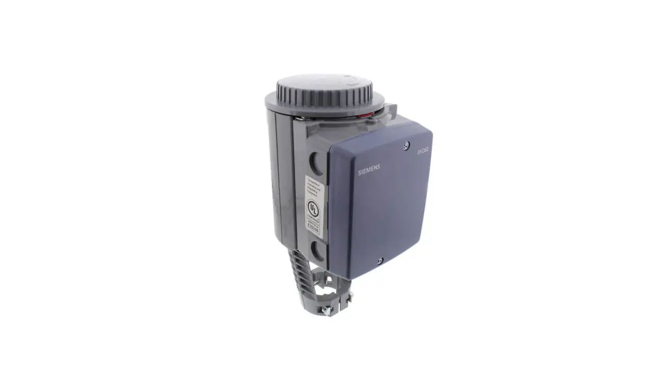
SIEMENS SKD62UA Electronic Valve Actuator
Product Description
The SKD…U actuator requires a 24 Vac supply signal to control a Flowrite™ 599 Series valve with a 3/4-inch (20 mm) stroke.
Product Numbers
- Non-Spring Return Spring Return
- SKD60U SKD62U
- SKD82.50U SKD82.51U
Warning/Caution Notations
- WARNING: Personal injury or loss of life may occur if you do not follow a procedure as specified.
- CAUTION: Equipment damage or loss of data may occur if you do not follow a procedure as specified.
Required Tools
- 5 mm Allen wrench
- Small and medium flat-blade screwdrivers
Expected Installation Time
- 20 minutes for factory-installed actuator
- 45 minutes for field replacement of actuator
Prerequisites
WARNING: If mounting the actuator to a valve already in line, either close the shut-off valves in the piping (upstream first, then downstream) or switch off the pump to allow the differential and static pressure in the valve to drop.
Mounting Positions
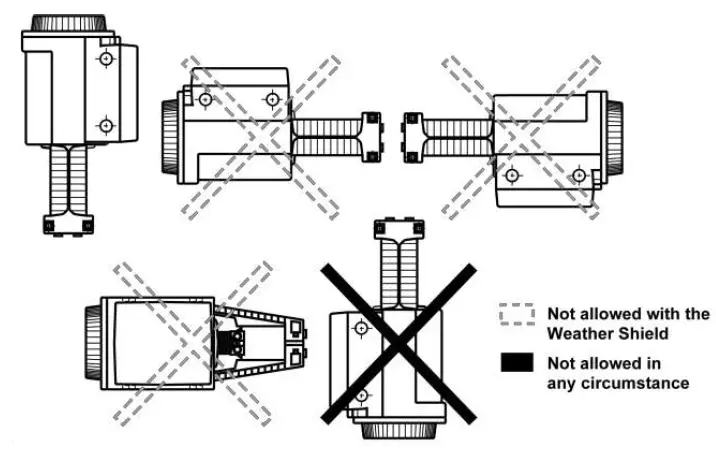
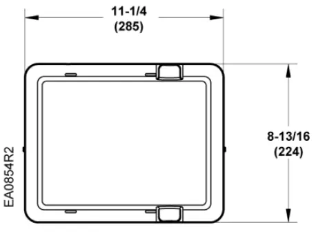
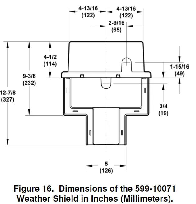
Using the Weather Shield
The SKD must be in the vertical position. Complete instructions for the mounting of the Weather Shield are included with that product.
NOTE: Use the top knockout position when installing the Weather Shield. 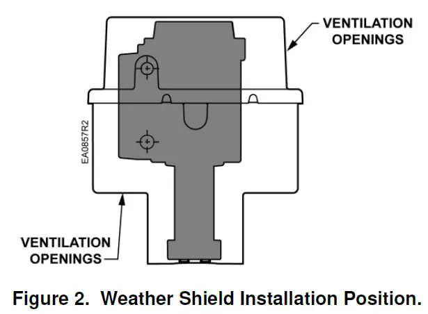
Installation
If you are mounting an actuator on a new valve, begin with the instructions in Figure 3.
Removing the Actuator from the Valve
- Remove the actuator cover.
- Disconnect the wires and conduit, if installed.
- Loosen the valve stem retainer using a 5 mm Allen wrench and lower the valve stem into the valve.
- Loosen the yoke nuts using a 5 mm Allen wrench in the actuator yoke.
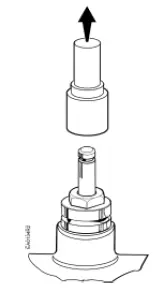
- Remove the actuator from the valve, being careful not to damage the valve stem.
Continue with Mounting an Actuator to a Valve.
Mounting an Actuator to a Valve.
NOTE: Install the stem heating element, (P/N ASZ6.6), if used, before proceeding.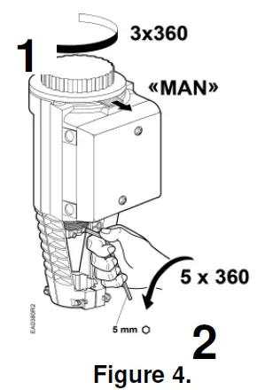
NOTE: Ensure the yoke nuts are loose enough to allow the actuator to slip over the bonnet. See Figure 5.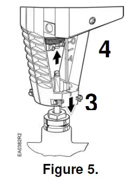
NOTE: Hold the stem retainer in place as you tighten it around the valve stem. See Figure 6.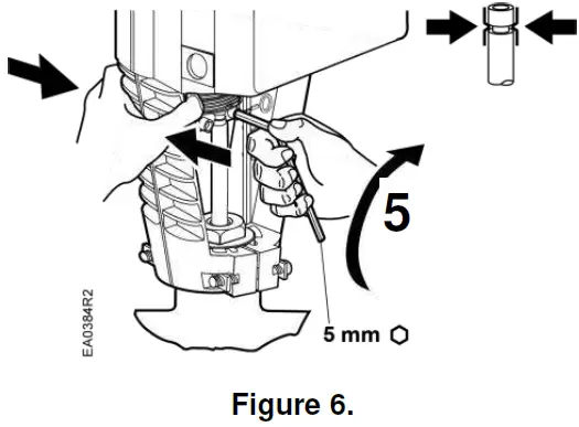
NOTE: Position the actuator to accommodate the wiring. Hold the actuator in place while tightening the yoke nuts. See Figure 7.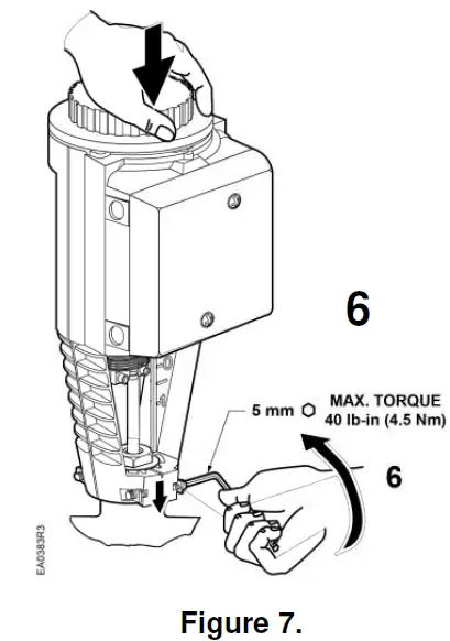
Wiring
CAUTION: Use care when removing the knockout. Do not damage the circuit board.
Do not use autotransformers. Use earth ground isolating step-down Class 2 transformers.
Determine supply transformer rating by summing total VA of all actuators used. The maximum rating for a Class 2 power supply circuit is 100 VA.
| Actuator | Power Consumption | Actuators Per Class 2 Supply Circuit* (80% of TransformerVA) |
| SKD6…U | 17 VA | 4 |
| SKD82.50U | 13 VA | 8 |
| SKD82.51U | 18 VA | 5 |
Operating more actuators requires additional transformers or separate 100 VA power supplies.
Wiring Diagrams
- SKD60U/SKD62U Figures 9 and 10
- SKD82.50U/51U Figures 11 through 13
SKD6…U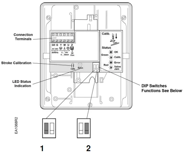
| DIP Switches | 1 Selection of Control Signal | 2 Selection of Flow Characteristic |
| ON | 4 to 20 mA | Modified* |
| OFF (Factory Setting) | 0 to 10 Vdc | Default |
*Changing the default setting will modify an equal percentage valve to a linear flow characteristic. When set to default, the flow characteristic is determined by the valve body.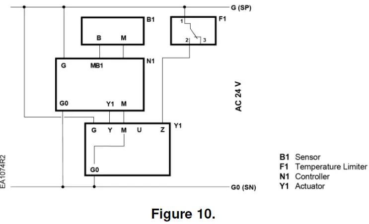
Connecting Terminals
| 24 Vac | |
| G | System Potential (SP) |
| G0 | System Neutral (SN) |
| Y | Control Input: 0 to 10 Vdc or 4 to 20 mA (DIP switch selectable) |
| Z | Override Control (See Technical Instructions 155-180P25) |
| M | Measuring Neutral |
| U | Output for 0 to 10 Vdc or 4 to 20 mA measuring voltage. It will match the input signal type. |
The position output signal U will switch from 0 to 10 Vdc to 4 to 20 mA when a 4 to 20 mA input signal is selected and used on the terminal.
Wiring for SKD82…U
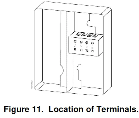
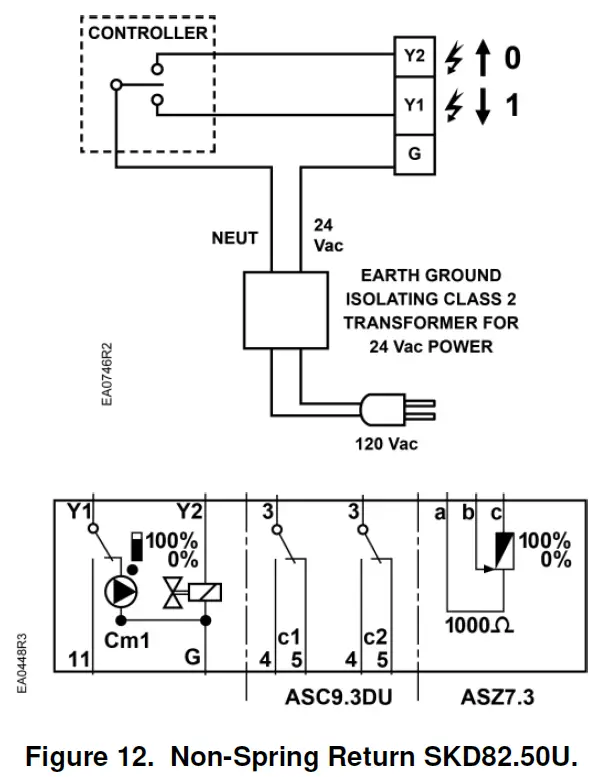
Connecting Terminals
| G | System Potential 24 Vac (+) |
| Y1 | Outward movement of coupling piece (0 to 1) |
| Y2 | Inward movement of coupling piece (1 to 0) |
| Cm1 | Limit switch for 100% stroke |
| c1 | ASC9.3DU double auxiliary switch |
| c2 | ASC9.3DU double auxiliary switch |
| 1000 W | ASZ7.3 potentiometer |
The diagram shows all possible connections. How many and which are used depend on the application.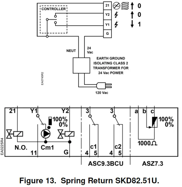
Connecting Terminals
| G | System Potential 24 Vac (+) |
| 21 | System Neutral (SN) |
| Y1 | Outward movement of coupling piece (0 to 1) |
| Y2 | Inward movement of coupling piece (1 to 0) |
| Cm1 | Limit switch for 100% stroke |
| c1 | ASC9.3DU double auxiliary switch |
| c2 | ASC9.3DU double auxiliary switch |
| 1000 W | ASZ7.3 potentiometer |
The diagram shows all possible connections. How many and which are used depend on the application.
Start-Up
Check the wiring for proper connections.
Consult Flowrite 599 Series SKD6xU Electronic Valve Actuators 24 Vac Proportional Technical Instructions 155-180P25 for detailed commissioning information.
Normally Closed Valve
Actuator pressure cylinder moves:
- Outward (0 to 1): Valve opens.
- Inward (1 to 0): Valve closes.
Normally Open Valve
Actuator pressure cylinder moves:
- Outward (0 to 1): Valve closes.
- Inward (1 to 0): Valve opens.
Three-Way Valve
Actuator pressure cylinder moves:
- Outward: Valve opens between port NC and C.
- Inward: Valve opens between ports NO and C.
NOTE: The valve body assembly determines the complete assembly action.
Reference
| Technical Instruction | Document Number |
| Flowrite EA599 Series SKD Electronic Valve Actuator Proportional Control | 155-180P25 |
| Flowrite EA599 Series SKD Electronic Valve Actuator 3-position (Floating) Control | 155-181P25 |
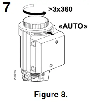
Manual Operation
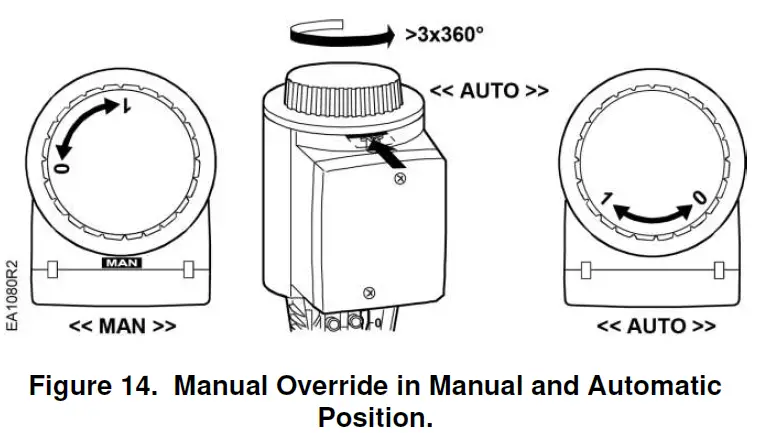
Each complete revolution (360°) is equal to a 3/32-inch (2.5 mm) stroke.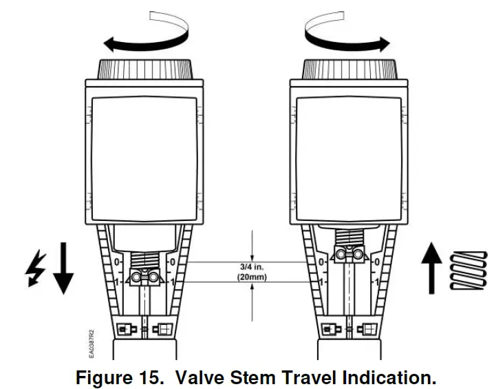
Dimensions
CAUTION: Be careful when removing the knockout. Do not damage the circuit board.
NOTE: Use the top knockout position when installing the Weather Shield.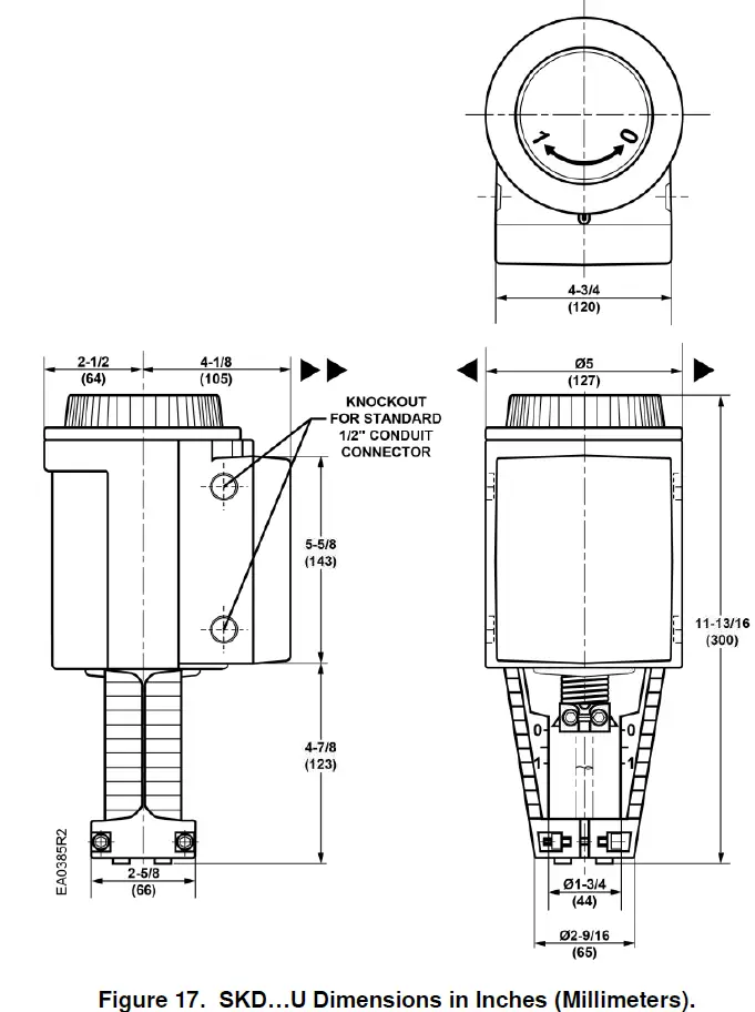
Information in this publication is based on current specifications. The company reserves the right to make changes in specifications and models as design improvements are introduced. Flowrite is a trademark of Siemens Industry, Inc. Other product or company names mentioned herein may be the trademarks of their respective owners. © 2018 Siemens Industry, Inc.
Siemens Industry, Inc.
Building Technologies Division
1000 Deerfield Parkway
Buffalo Grove, IL 60089-4513
USA
Tel. +1 847-215-1000
Your feedback is important to us. If you have comments about this document, please send them to [email protected]
Document No. 129-217
Printed in the USA


