![]()
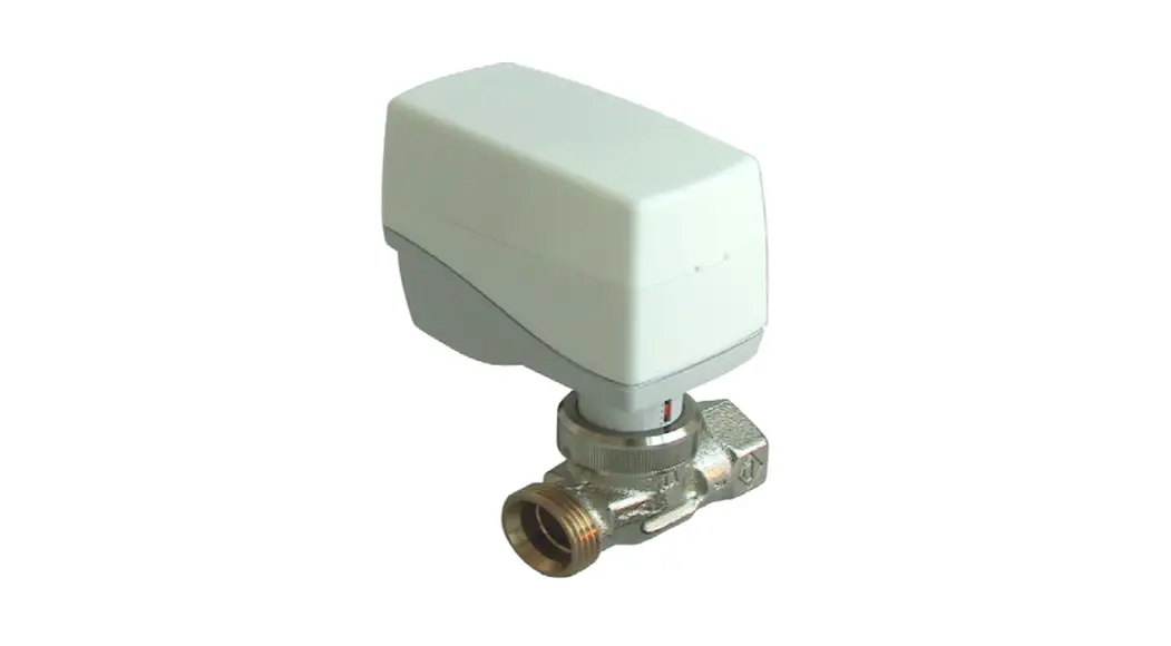
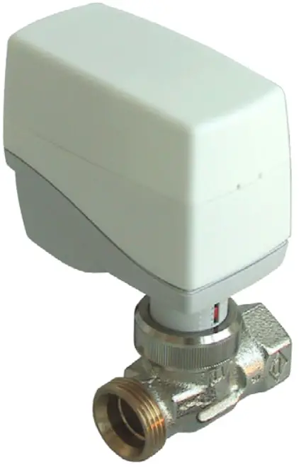
M9-MD15 Intelligent Valve Actuator
Instruction Manual
M9-MD15
Intelligent Valve Actuator
M9-MD15 Intelligent Valve Actuator
IMPORTANT!
Be sure to install the MD15 Valve Actuator
PRIOR TO INSTERTING BATTERIES & PAIRING the device!
Application Small radio controlled, battery-powered actuator for room temperature control. For thermostat valve bodies for direct mounting on commercially available radiator valves for room-specific temperature control in heating systems.
The actuator is radio controlled based on the non-proprietary EnOcean radio protocol. The following EnOcean Equipment Profile (EEP) is supported: EEP A5-20-01 Battery Powered Actuator
Safety Instructions
This data sheet contains information on installing and commissioning the product Mx-MD15. Each person who carries out work on this product must have read and understood this data sheet. If you have any questions that are not resolved by this data sheet, you can obtain further information from the supplier or manufacturer.
If the product is not used in accordance with this data sheet, the protection provided will be impaired. Applicable regulations must be observed when installing and using the device. Within the EU, these include regulations regarding occupational safety and accident prevention as well as those from the VDE (Association for Electrical, Electronic & Information Technologies).
If the device is used in other countries, it is the responsibility of the system installer or operator to comply with local regulations. Mounting, installation and commissioning work on the devices may only be carried out by qualified technicians. Qualified technicians are persons who are familiar with the described product and who can assess given tasks and recognize possible dangers due to technical training, knowledge and experience as well as knowledge of the appropriate regulations.
Technical Specifications
| Part Numbers (Frequency Dependant) | M9-MD15 (902 MHz – North America) M8-MD15 (868 MHz – Europe and China) MJ-MD15 (928 MHz – Japan) |
| Nominal Voltage | Battery-Operated, 3 alkaline AA batteries (LR6AD Panasonic Powerline 1.5 V) |
| Battery Life | Depends on the frequency and method of operation – approx. 3 years with default settings |
| Measuring System | Integrated digital temperature sensor; 0..40 °C; ±0.5 °C at 25 °C |
| Interfaces | EnOcean® radio interface: – Radio telegram: EnOcean radio telegram, bidirectional – EEP A5-20-01 (Battery Powered Actuator) – Frequency: 868.3 MHz – Range: approx. 30 m in buildings (depending on building structure) – Duty cycle: < 1 % – Transmission/reception interval: every 2..20 min, can be set in 2 min increments |
| Motor Switch-Off | Actuator spindle: when extending = load-dependent, when retracting = path-dependent |
| Display | Multicolored status LED |
| Actuating Noise | < 28 dB (A) |
| Nominal Stroke | Up to 3 mm |
| Travel Time | 10 s/mm |
| Positioning Force | 100 N (nominal) |
| Position Indication | Stroke range scale |
| Housing | RAL 9010 pure white, battery compartment cover with mechanical locking mechanism |
| Ambient temp. | 0..50°C |
| Degree of Protection | IP40 |
| Installation Position | Anywhere from vertical to horizontal |
| Maintenance | Maintenance-free |
| Weight | 157 g (without batteries); 225 g (with batteries |
– When used properly, this device complies with the requirements of the R&TTE Directive (1999/5/EC).
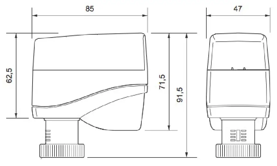
Dimensions
Radio Small Actuator Functions
Actuator mode
If a 0 to 100% EnOcean telegram is received from an external radio partner for controlling the radio small actuator, the internal loop controller is not active. The transmitted actuating signal is translated into a positioning movement. A suitable radio single room controller takes over the control functions.
Self-controlling operation
The integrated room temperature controller is activated if no external 0 to 100% EnOcean radio telegram is received.
Without external operator panel (= emergency mode):
The temperature is controlled to a fixed setpoint of 20 °C using the integrated temperature sensor (actual value) and the integrated control function of the actuator.
With external operator panel (EnOcean technology):
Using the operator panel, the users can freely determine the setpoint or enter their own schedule. The actual value and the setpoint are transmitted via an EnOcean telegram (EEP A5-20-01). The integrated control algorithm makes room control easy and convenient.
Battery monitoring
The battery capacity is continuously monitored. If the battery capacity is too low, a radio signal is transmitted to the radio partner and 2 acoustic signal tones are emitted in succession every 6 hours. If this message is activated, the remaining capacity of the batteries is
< 10%.
CAUTION:
The batteries must be replaced within the next 30 days.
As the battery level decreases, the interval between the audible signals becomes shorter and the number of signal tones increases to 4 signal tones in succession every 3 hours. If the remaining battery capacity is insufficient to maintain motorized operation, the actuator
moves into the safety position of 50%. The radio communication with the radio partner still functions in this operating state.
Valve Recognition
During commissioning, the actuator detects the closing point and the total stroke of the valve. After the batteries are changed or after the unit is successfully taught in on a radio partner, this detection process is performed again via the Init.
Valve block protection
Block protection prevents the cone from jamming when the valve is inactive for a long time. When block protection is active, the actuator performs a displacement of 50% once every 21 days. If the remaining battery level is < 10% (see “Battery monitoring” section), this
function is inactive. This function can be switched on and off.
Automatic closing point control
The small actuator continuously monitors the closing point and corrects it if necessary.
Communication test
The radio communication path to the radio partner is checked. Performing a communication test has no effect on the transmission/ reception interval.
Energy block (automatic “Window open” recognition)
When a window is open, the flow of heat energy to the room is interrupted. An open window is signified by a large and rapid temperature drop at the Mx-MD15 small actuator. If such a drop is measured by the internal temperature sensor, the small actuator closes the valve for 30 min. After 30 minutes, the small actuator returns to normal operation and the automatic “Window open” recognition function is active again.
Frost protection function
If the temperature at the integrated temperature sensor drops below 6 °C, the small actuator opens the valve until 8 °C is reached.
Summer mode
If the status message “Summer mode on” is received from an external radio partner, the small actuator closes the valve.
The transmission/reception interval in summer mode is permanently set to 60 minutes.
Radio Interface
The communication with the radio partner is cyclical, bidirectional and includes intelligent reception/ transmission management.
Upon the first reception of the radio telegram, the radio small actuator automatically adapts its operating mode according to the method of control from the radio partner (actuator mode or self-controlled mode).
NOTE:
If the communication with the radio partner is disrupted, the “emergency mode” status bit (self-controlled mode) is set (can be evaluated for service diagnostics). After the malfunction has been rectified (details can be found in the documentation of the radio partner), the radio partner is automatically resynchronized.
CAUTION:
This product uses only EnOcean telegrams. When selecting a radio partner, ensure that the radio interface also works with the EnOcean telegram EEP A5-20-01 (Battery Powered Actuator).
EnOcean Equipment Profiles EEP A5-20-01 (Battery Powered Actuator)
| Transmit Mode | Message from the actuator to the controller |
| DB_3 | Current Value value 0…100%, linear n=0…100 |
| DB_2.BIT_7 | Service on |
| DB_2.BIT_6 | Energy input enabled (not applicable) |
| DB_2.BIT_5 | Energy Storage > xx% charged (not applicable) |
| DB_2.BIT_4 | Battery capacity > 10% |
| DB_2.BIT_3 | Contact, cover open |
| DB_2.BIT_2 | Failure temperature sensor, out of range |
| DB_2.BIT_1 | Detection, window open |
| DB_2.BIT_0 | Actuator obstructed |
| DB_1 | Temperature 0…40°C, linear n=0…255 |
| DB_0.BIT_7 | Not used |
| DB_0.BIT_6 | Not used |
| DB_0.BIT_5 | Not used |
| DB_0.BIT_4 | Not used |
| DB_0.BIT_3 | LRN Bit 0b0 Teach-in telegram 0b1 Data telegram |
| DB_0.BIT_2 | Self-controlled mode 0b0 off 0b1 on |
| DB_0.BIT_1 | Not used |
| DB_0.BIT_0 | Not used |
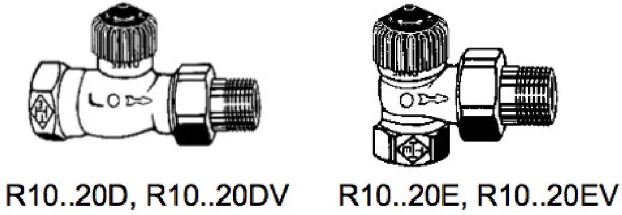
R10..20D/E/DV/EV Two-Way Valves for MD15-FTL-HE Radio Small Actuator
| Receive Mode | Commands from the controller to the actuator |
| rx tim = max. 1s | Note: The data transfer from the radio partner to the radio small actuator must be completely finished within a maximum time window of 1s. |
| DB_3 | Valve set point 0…100 %, linear n=0…100 Temperature set point 0…40°C, linear n= 0…255 |
| DB_2 | Temperature actual from RCU = 0b0, Room controller-unit … |
| DB_1.BIT_7 | Run init sequence, only active in service mode |
| DB_1.BIT_6 | Lift set, only active in service mode |
| DB_1.BIT_5 | Valve open, only active in service mode |
| DB_1.BIT_4 | Valve closed, only active in service mode |
| DB_1.BIT_3 | Summer bit, reduction on energy consumption |
| DB_1.BIT_2 | Set point selection DB_3 0b0 set point 0…100% 0b1 temperature set point 0…40°C |
| DB_1.BIT_1 | Set point inverse |
| DB_1.BIT_0 | Select function 0b0 RCU 0b1 Service on |
Types:
PN10 gunmetal two-way valve for the small actuator (water up to 120°C)
| Type | DN | PN | Kvs | R | |
| Straight throughput | R10D | 10 | 10 | 1.25 | 3/8” |
| R15D | 15 | 10 | 1.35 | 1/2” | |
| R20D | 20 | 10 | 2.5 | 3/4” | |
| Right-angled throughput | R10E | 10 | 10 | 1.25 | 3/8” |
| R15E | 15 | 10 | 1.35 | 1/2” | |
| R20E | 20 | 10 | 2.5 | 3/4” | |
| Straight throughput with Kvs setting | R10DV | 10 | 10 | 0.73 | 3/8” |
| R15DV | 15 | 10 | 0.73 | 1/2” | |
| R20DV | 20 | 10 | 0.73 | 3/4” | |
| Right-angled throughput with Kvs setting | R10EV | 10 | 10 | 0.73 | 3/8” |
| R15EV | 15 | 10 | 0.73 | 1/2” | |
| R20EV | 20 | 10 | 0.73 | 3/4” |
Technical Data – R10..20D/E/DV/EV Valves
| Nominal Diameter | DN10 – 20 |
| Pressure Rating | PN10 |
| Connection | Pipe screw connections in accordance with DIN EN 2115 |
| Actuating Stroke | 2 mm |
| Temperature of Medium | Water up to 120°C |
| Housing | Gunmetal; nickel-plated |
| Cone | EPDM |
| Valve Spindle | Stainless steel |
| Spindle Seal | EPDM |
| Maintenance | Maintenance-free |
 Dimensions
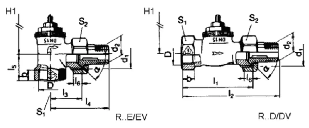 Kvs default setting R10 – 20DV/EV valves
To adjust to the heat requirement, the R10 – 20DV/EV valves have 8 flow settings for the radiator mass flow rate.
The maximum flow rate, Kvs value (m3/h) can be selected by using the settings 1, 2, 3, 4, 5, 6, 7 or 8 (delivery setting = 8, corresponds to a Kvs value = 0.86).
The setting can be made using a Z29 socket key (accessory). The setting between 1 and 8 can be read from the valve, and will be implemented by the installed small actuator.
| Position | 1 | 2 | 3 | 4 | 5 | 6 | 7 | 8 |
| Kvs Value | 0,049 | 0,102 | 0,185 | 0,313 | 0,420 | 0,565 | 0,740 | 0,860 |
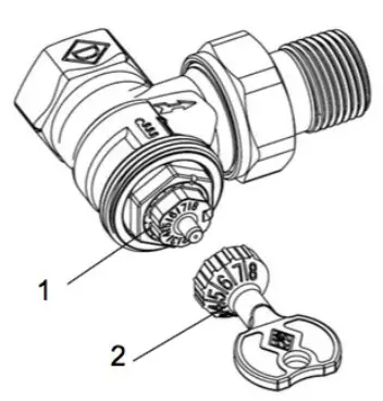
- Setting marks
- Z29 socket key (accessory )
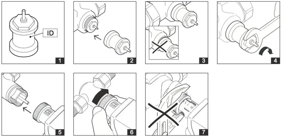
Valve Installation
CAUTION
The valve may only be installed by qualified technicians. In addition to the generally valid installation guidelines, the following points are to be observed:
– The pipeline system and the interior of the fitting must be free of foreign objects. In the event of contaminated media, dirt collectors are to be inserted upstream of the valves with fine screens, mesh width 0.25 mm.
– There must be no tension between the valve and the pipeline connection.
– To avoid eddy formations in the valve body, the valve should be installed in a straight section of the pipe. A distance of 10 times the nominal diameter is recommended between the valve flange and manifold or other similar parts.
– The installation location is to be selected so that the ambient temperature at the actuator is kept between 0 – +50 °C.
– When carrying out installation, the permissible maximum pressure difference ∆p and the specified direction of flow must be observed (see table in “Types” section).
– Once the valve is installed, make sure the ball in the valve seating can be moved easily by pushing in the valve stem.
– Approximately 30 mm of free space is required above the actuator to install the actuator and remove the housing cover.
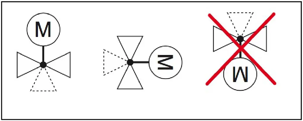
– For safety reasons, do not suspend the small actuators from under the valve.
– Observe the direction of flow arrow on the valve body. Inverting the direction of flow impairs control behavior.
Installing the Radio Small Actuator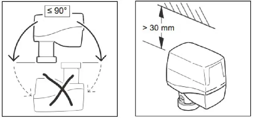
CAUTION
Insert the batteries with the correct polarity.
When inserting the batteries, observe the polarity as marked in the battery compartment. Use only alkaline batteries (type: AA, LR6 1.5 V)
-MD15-FTL-HE, MD15-FTL-OV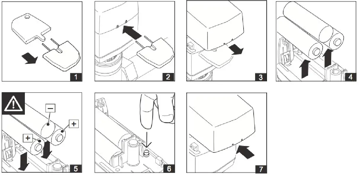 – Open the battery compartment cover using the special key supplied by inserting it into the intended place. Remove the cover.
The special key is included with delivery of the small actuator.
– Inserting the batteries and close the battery compartment cover.
– Place the small actuator on the threaded connection of the valve and tighten hand-tight using the union nut.
Installing Accessories Z800 to Z816
Z802..Z805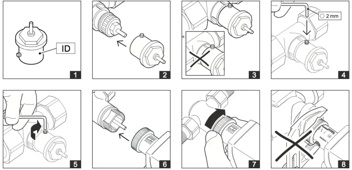
Z800..Z801 and Z806..816
CAUTION:
Before beginning to remove the unit, make sure that no differential pressure builds up in the valve body before beginning work. If necessary, close the gate valve and turn off pumps. After the pipeline has cooled off, you can begin removal of the small actuator.
-MD15-FTL-HE, MD15-FTL-OV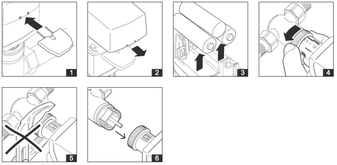
– Open the battery compartment cover using the special key supplied by inserting it into the intended place. Remove the cover.
The special key is included with delivery of the small actuator.
– Remove the battery.
– Loosen the union nut.
– Remove the small actuator from the valve.
Commissioning
-Overview of functions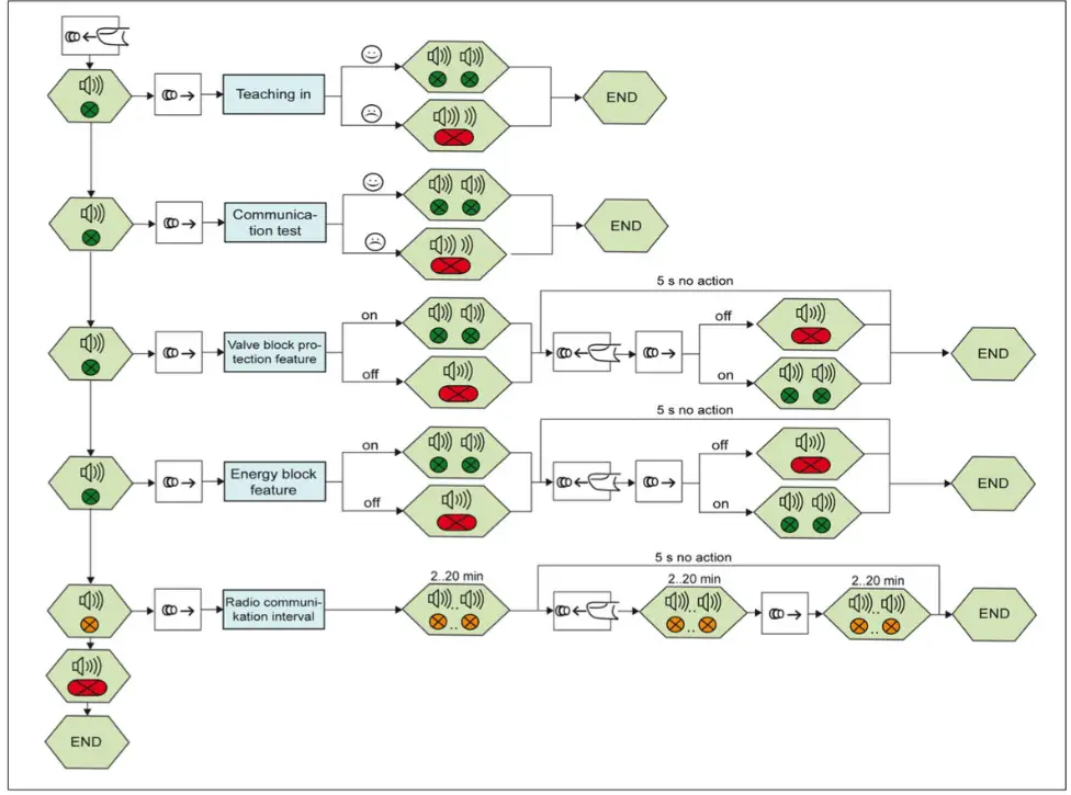
CAUTION
This product description describes specific settings and functions of the Mx-MD15. In addition to these instructions, the product descriptions of other system components, such as radio partners, are to be observed.
– The buttons and LED displays that are used during commissioning are located inside the housing.
– Remove the housing cover before commissioning.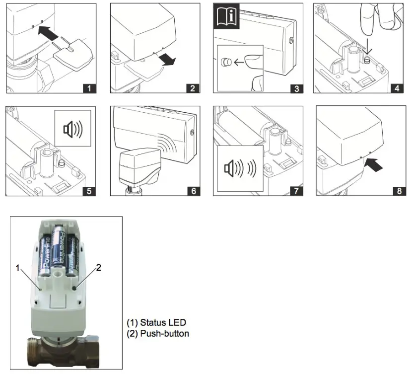
Teaching In the Radio Small Actuator on a Radio Partner
– Set the radio partner to teach-in standby mode. Details are described in the documentation of the radio partner.
– To trigger a teach-in telegram on the Mx-MD15, press the push-button (2) on the Mx-MD15 until a signal tone is heard and the status LED (1) lights up green (.
– Release the push-button (2).
The teach-in process is started.
The radio partner confirms that the teach-in process was successful.
Details are described in the documentation of the radio partner.
The radio small actuator confirms that the teach-in process was successful both visually (status LED flashes green 2 times) and acoustically (2 signal tones in succession).
An initialization run is automatically carried out.
– Close the housing of the MD15-FTL-xx by snapping on the housing cover.
NOTE
After the teach-in procedure has been successfully completed, the device ID of the radio partner is permanently stored in the radio small actuator. You do not need to perform the teach-in procedure again if you change the batteries.
NOTE
If the teach-in process was not successful, this is indicated visually (status LED flashes red for approx. 1 s) and acoustically (downward sequence of tones).
Start the teach-in process again.
Deleting the Radio Partner
It is not possible to delete the device ID of the radio partner which is saved internally on the Mx-MD15. This ID is overwritten by the new radio ID when a new teach-in process is performed.
Performing a Communication Test
– Press the push-button (2) and hold it until you hear 2 successive signal tones and the status LED flashes green 2 times.
– Release the push-button.
After the push-button (2) is released, the radio communication path to the radio partner is checked.
A successful communication test is indicated both visually (status LED flashes green 2 times) and acoustically (2 signal tones in succession).
NOTE
A successful communication test may require an adjustment of the current valve position.
If the communication test was not successful, this is indicated visually (status LED flashes red for approx. 1 s) and acoustically (downward sequence of tones). The radio small actuator switches to emergency mode.
NOTE
In case of an unsuccessful communication test, check the radio partner and the transmission path.
NOTE
If the communication with the radio partner is interrupted for longer than 1 h, the radio small actuator switches to emergency mode (see page 5) and the “emergency mode” status bit (self-controlled mode) is activated. When a correct telegram is received, the radio small actuator automatically returns to normal operation.
Switching the Valve Block Protection Feature On and Off
– Press the push-button (2) and hold it until you hear 3 successive signal tones and the status LED flashes green 3 times.
– Release the push-button.
After the push-button (2) is released, the current status (on or off) is indicated visually and acoustically.
-Valve block protection feature on: Status LED flashes green 2 times and 2 signal tones are emitted
– Valve block protection feature off: Status LED flashes red for approx. 1 s and a long signal tone is emitted
– To change the status, you must again press and release the push-button (2) within the next 5 s. The new function setting, either “valve block protection feature on” or “valve block protection feature off,” is indicated visually and acoustically as described above.
Factory setting: On
Setting the Radio Communication Interval
The transmission/reception interval can be set in 2 min increments, from 2 min to 20 min.
– Press the push-button (2) and hold it until you hear 5 successive signal tones and the status LED flashes green 4 times and orange 1 time.
– Release the push-button (2).
After the push-button (2) is released, the current radio communication interval is indicated visually and acoustically; see Table below “Radio communication interval”.
– To change the radio communication interval, you must press the push-button (2) again within the next 5 s and release it once the desired radio communication interval is reached.
This is indicated visually and acoustically; see Table below.
– Release the push-button (2).
The new radio communication interval is acknowledged again both visually and acoustically;
Default setting: Transmission and reception interval: 10 min
| Radio Communication Interval | Signal |
| 2 min | Status LED flashes 1 time and 1 signal tone is emitted |
| 4 min | Status LED flashes 2 times and 2 signal tones are emitted |
| : | : |
| 20 min | Status LED flashes 10 times and 10 signal tones are emitted. |
NOTE
If you press and hold the push-button (2) until 6 successive signal tones are heard and the status LED flashes 6 times, the status LED lights up red and a long signal tone (approx. 1 s) is emitted to indicate the end of the setting procedure.
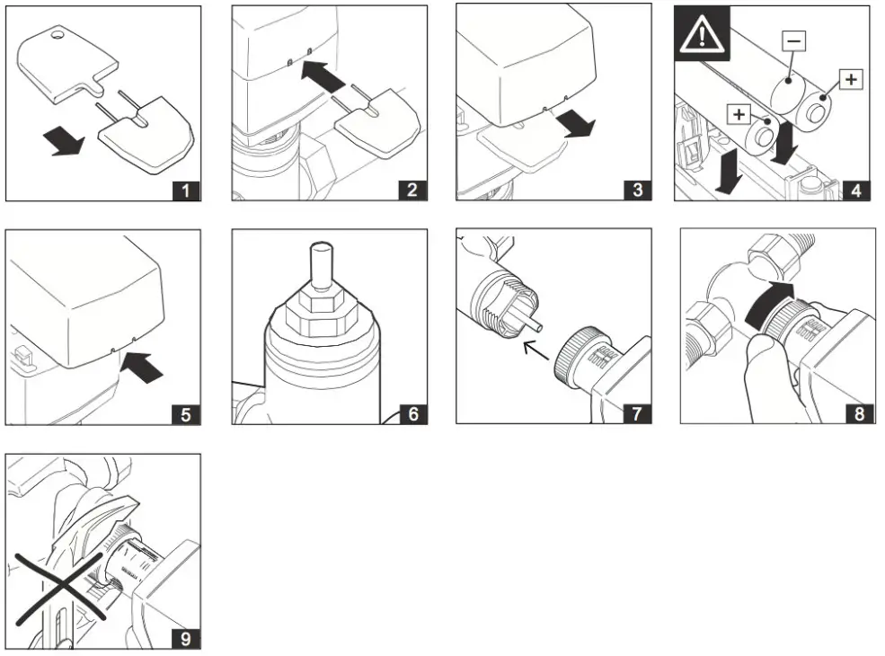
Replacing Batteries
– Open the battery compartment cover using the special key supplied by inserting it into the intended place. Remove the cover.
The special key is included with delivery of the small actuator.
– Remove the batteries.
– Insert batteries and briefly press the push-button.
– Close the battery compartment cover.
CAUTION
Insert the batteries with the correct polarity.
When inserting the batteries, observe the polarity as marked in the battery compartment. Use only alkaline batteries (type:AA, LR6 1.5 V).
NOTE
After changing the batteries, the radio small actuator goes into storage mode (actuator spindle is retracted). When the actuator receives a radio signal, it switches over to normal operation.
CAUTION
If the battery is changed on the disassembled radio actuator, the radio actuator remains operational. Assembly can only be performed on the valve if no positioning movements are being carried out on the radio actuator.
NOTE
Disposing of batteries in an environmentally friendly manner
Batteries are marked with this symbol. This symbol indicates that it is prohibited to dispose of batteries in the household waste. Dispose of used batteries at an approved collection point or store in accordance with legal regulations, or follow the applicable guidelines in your country for reducing harmful waste caused by batteries.
![]() Magnum First – 1 Seneca Street, 29th
Magnum First – 1 Seneca Street, 29th
Floor, M55 – Buffalo, NY 14203
– phone 716-293-1588
– www.magnumfirst.com
– [email protected]


