![]() GMS-GPS Receiver Module
GMS-GPS Receiver Module
User Manual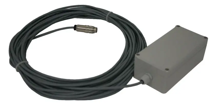
Document Revision
| Version | Date | Modification | Prepared | Checked | Released |
| 1 | 2012-12-05 | First issue | ANB | SER | TAB |
| 2 | 2012-12-20 | Pin out and config | MAE | JOG | TAB |
| 3 | 2022-09-01 | Pin out of RS485 cabling | JLT | ALB | KEC |
Disclaimer
GeoSIG Ltd reserves the right to change the information contained in this document without notice. While the information contained herein is assumed to be accurate, GeoSIG Ltd assumes no responsibility for any errors or omissions.
Copyright Notice
No part of this document may be reproduced without the prior written consent of GeoSIG Ltd. Software described in this document is furnished under a license and may only be used or copied in accordance with the terms of such a license.
Trademark
All brand and product names mentioned are trademarks or registered trademarks of their respective holders.
All rights reserved.
GeoSIG Ltd
Switzerland
Warnings and Safety
![]() The GPS system is operated by the government of the United States of America, which is solely responsible for its accuracy and maintenance.
The GPS system is operated by the government of the United States of America, which is solely responsible for its accuracy and maintenance.![]() GPS provides only UTC time at 0° Greenwich meridian without daylight savings time adjustment.
GPS provides only UTC time at 0° Greenwich meridian without daylight savings time adjustment.
Symbols and Abbreviations
| Instrument | GeoSIG Recorder, Digitiser or Data Acquisition system |
| GPS | Global Positioning System |
| UTC | Universal Time Clock |
Introduction
This document describes the principle of operation and installation instructions of the GPS.
The GPS device is used with GeoSIG Instruments to provide the global coordinates of the GPS antenna and accurate date and time to the Instruments. It’s very useful for precise synchronisation of one or several interconnected Instruments.
GPS provides only UTC time at 0° Greenwich meridian without daylight savings time adjustment.![]() The GPS device is provided in a box with a cable length to be defined at the time of order or provided by the customer.
The GPS device is provided in a box with a cable length to be defined at the time of order or provided by the customer.
GPS Cable
Two different cables can be used according to connection:
| · GPS – RS-232 (standard): | Up to 70 meters of cable length |
| · GPS – RS-485: | Up to 300 meters of cable length |
2.1. GPS RS-232 cable
For the RS-232 connection, the cable used by default is:![]() GeoSIG standard cable type: XY DIN 5 x 0.25 mm2 gr UL style 2464.
GeoSIG standard cable type: XY DIN 5 x 0.25 mm2 gr UL style 2464.
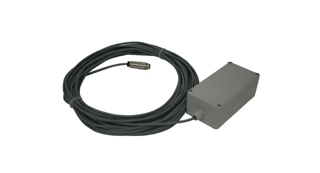
Figure 1. Example of GPS device RS-232 assembled with 20 m of cable for an Instrument
2.2. GPS RS-485 cable
For the RS-485 connection, the cable used by default is:![]() GeoSIG standard cable type: LiY(St)CY 300V 4 x 2 x 0.25 mm2 gr UL Style 2464.
GeoSIG standard cable type: LiY(St)CY 300V 4 x 2 x 0.25 mm2 gr UL Style 2464.
Figure 2. Example of GPS device RS-485 assembled with 20 m of cable for an Instrument
Mounting the GPS Box
It is recommended to perform a check of the GPS function before mounting the box to its final location, as described in section 5.
The GPS device box can be fixed to various locations. The position of the box should be defined according to a position where GPS antenna can easily get the satellite signals. Typically the box is fixed on an outside wall or on a roof. This is an important point as the antenna should receive signals from at least 3 satellites for synchronisation of the instrument.![]() Make sure that at least 75% of the sky is visible at all times over the GPS box.
Make sure that at least 75% of the sky is visible at all times over the GPS box.
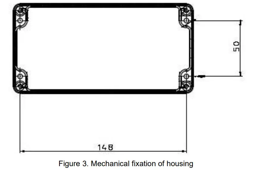
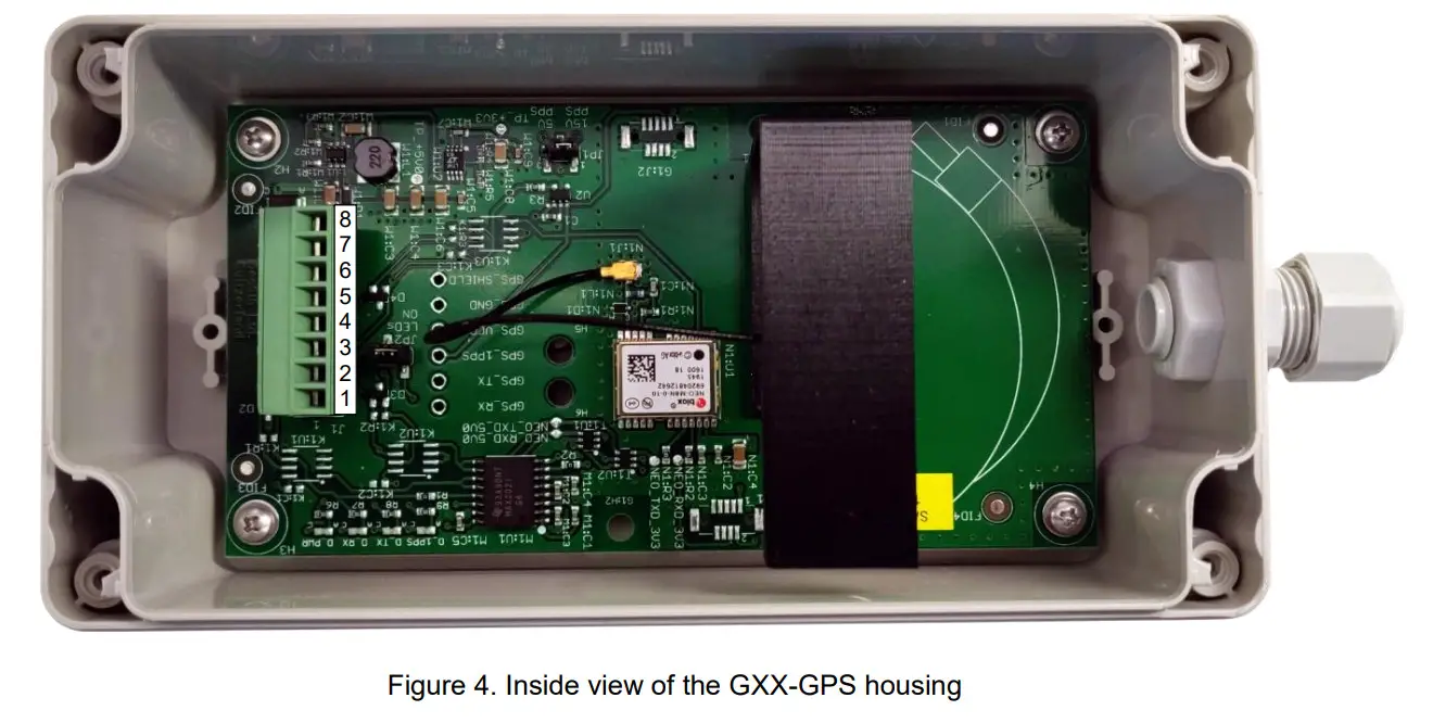
Fixation of the housing should be done with M4 screws with spacing and locations as shown in Figure 3 and Figure 4. Type of screw depends on the type of surface where the box will be fixed.
Electrical Connection
4.1. GPS Main Connector Pin Assignment
4.1.1. With RS-232 connection
The GPS device is provided with an 8-pin main connector inside the box, supplied already connected.
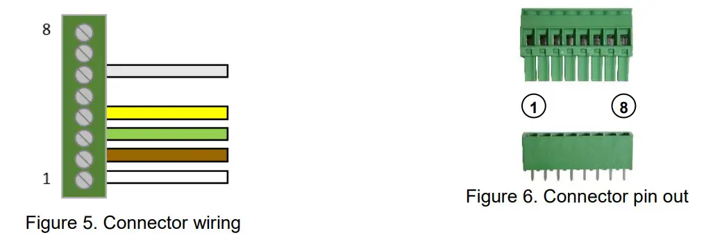
Table 1. Electrical connections of the RS-232 GPS device connector
Pin | Signal | Standard cable Colours | Comment |
| 1 | GPS_RX_P | White | Reception signal from instrument |
| 2 | GPS_TX_P | Brown | Transmit signal of GPS |
| 3 | GPS_1PPS_P | Green | 1 PPS signal of GPS |
| 4 | V_MAIN | Yellow | 12V power from instrument |
| 5 | GPS_1PPS_N | N/A | Only used for RS-485 |
| 6 | GND | Grey | Ground from instrument |
| 7 | GPS_RX_P | N/A | Only used for RS-485 |
| 8 | GPS_TX_N | N/A | Only used for RS-485 |
4.1.2. With RS-485 connection
The GPS device is provided with an 8-pin main connector inside the box, supplied already connected.
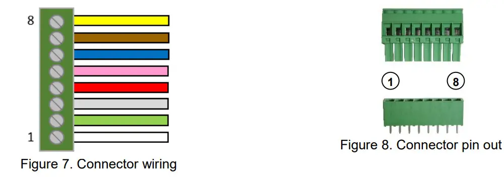
Table 2. Electrical connections of the RS-485 GPS device connector
Pin | Signal | Standard cable Colours | Comment |
| 1 | GPS_RX_P | White | Reception signal from instrument+ |
| 2 | GPS_TX_P | Green | Transmit signal of GPS+ |
| 3 | GPS_1PPS_P | Grey | 1 PPS signal of GPS+ |
| 4 | V_MAIN | Red | 12V power from instrument |
| 5 | GPS_1PPS_N | Pink | 1 PPS signal of GPS- |
| 6 | GND | Blue | Ground from instrument |
| 7 | GPS_RX_N | Brown | Reception signal from instrument- |
| 8 | GPS_TX_N | Yellow | Transmit signal of GPS- |
4.2. Mating Connector at the Instrument Side
A mating connector must be used for connecting the GPS device to an Instrument. This connector is already assembled when the GPS is ordered together with the Instrument.
4.2.1. GXR-XX Device
4.2.1.1. Mating Connector at the Instrument Side for RS-232 connection
Table 3. Electrical connections of an Instrument’s GPS device input connector
Pin | Signal | Standard Cable Colours | Comment |
| 1 | GPS_RXD | White | Transmit signal of GSR |
| 2 | GPS_TXD | Brown | Reception signal of GSR |
| 3 | GPS_STDBY | N/A | Not connected |
| 4 | GND | N/A | Not connected |
| 5 | GPS_1PPS | Green | 1 PPS signal from GPS |
| 6 | V_MAIN | Yellow | 12V power from instrument |
| 7 | GND | Grey | Ground from instrument |
4.2.1.2. Mating Connector at the Instrument Side for RS-485 connection
Table 4. Electrical connections of an Instrument’s GPS device input connector
Pin | Signal | Standard Cable Colours | Comment |
| 1 | N/A | N/A | Not connected |
| 2 | SYNCI_RX+ | White | GPS Transmit signal+ |
| 3 | N/A | N/A | Not connected |
| 4 | SYNCI_RX- | Brown | GPS Transmit signal- |
| 5 | GPS_1PPS | Green | 1 PPS signal from GPS |
| 6 | V_EXT_GPS | Yellow | 12V power from instrument |
| 7 | GND_EXT | Grey | Ground from instrument |
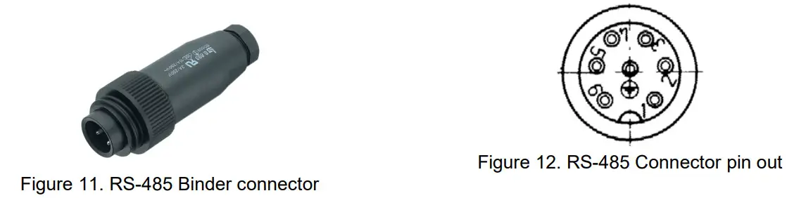
4.2.2. GMS Devices
This includes the instruments GMS-XX and GMSplus.
4.2.2.1. Mating Connector at the Instrument Side for RS-232 connection
Table 5. Electrical connections of an Instrument’s GPS device input connector
Pin | Signal | Standard Cable Colours | Comment |
| 1 | GPS_RXD | White | Reception signal from instrument |
| 2 | GPS_TXD | Brown | Transmit signal of GPS |
| 3 | GPS_STDBY | N/A | Not connected |
| 4 | GND | N/A | Not connected |
| 5 | GPS_1PPS | Green | 1 PPS signal from GPS |
| 6 | V_MAIN | Yellow | 12V power from instrument |
| 7 | GND | Grey | Ground from instrument |
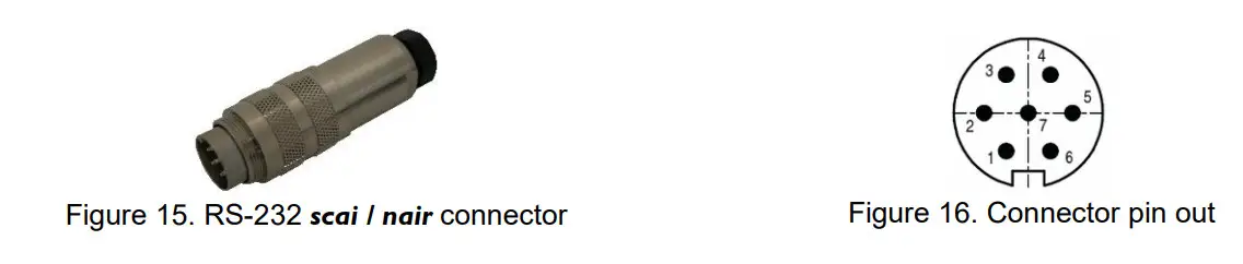
4.2.3. SCAI or NAIR Device
4.2.3.1. Mating Connector at the Instrument Side for RS-232 connection
Table 6. Electrical connections of an Instrument’s GPS device input connector
Pin | Signal | Standard Cable Colours | Comment |
| 1 | GPS_1PPS+ | Green | 1 PPS signal from GPS |
| 2 | GPS_1PPS- | N/A | Not connected |
| 3 | TX+ | Brown | Transmit signal of GPS |
| 4 | TX- | N/A | Not connected |
| 5 | RX+ | White | Reception signal from instrument |
| 6 | RX- | N/A | Not connected |
| 7 | SUPPLY+ | Yellow | 12V power from instrument |
| 8 | SUPPLY- | Grey | Ground from instrument |
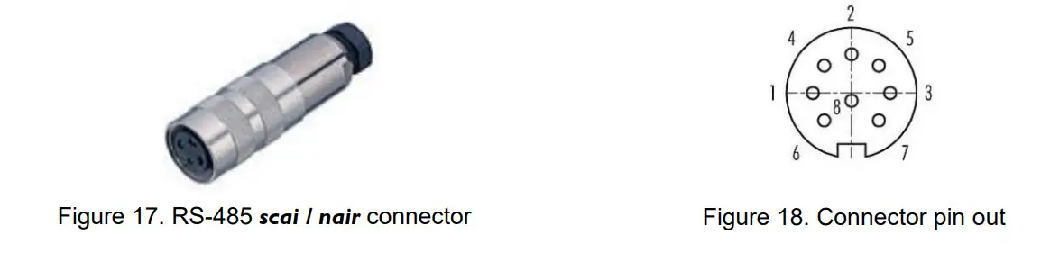
4.2.3.2. Mating Connector at the Instrument Side for RS-485 connection
Table 7. Electrical connections of an Instrument’s GPS device input connector
Pin | Signal | Standard Cable Colours | Comment |
| 1 | GPS_1PPS+ | Grey | 1 PPS signal from GPS |
| 2 | GPS_1PPS- | Pink | Not connected |
| 3 | TX+ | Green | Transmit signal of GPS |
| 4 | TX- | Yellow | Not connected |
| 5 | RX+ | White | Reception signal from instrument |
| 6 | RX- | Brown | Not connected |
| 7 | SUPPLY+ | Red | 12V power from instrument |
| 8 | SUPPLY- | Blue | Ground from instrument |
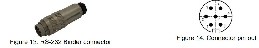
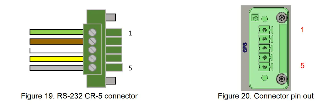
4.2.4. CR-5 Device
4.2.4.1. Mating Connector at the Instrument Side for RS-232 connection
Table 8. Electrical connections of an Instrument’s GPS device input connector
Pin | Signal | Standard Cable Colours | Comment |
| 1 | GPS_1PPS+ | Green | 1 PPS signal from GPS |
| 2 | TX+ | Brown | Transmit signal of GPS |
| 3 | RX+ | White | Reception signal from instrument |
| 4 | SUPPLY+ | Yellow | 12V power from instrument |
| 5 | SUPPLY- | Grey | Ground from instrument |
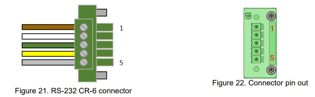
4.2.5. CR-6 / CR-6plus Device
4.2.5.1. Mating Connector at the Instrument Side for RS-232 connection
Table 9. Electrical connections of an Instrument’s GPS device input connector
Pin | Signal | Standard Cable Colours | Comment |
| 1 | RX+ | Brown | 1 PPS signal from GPS |
| 2 | TX- | White | Transmit signal of GPS |
| 3 | GPS_1PPS | Green | Reception signal from instrument |
| 4 | V_EXT_GPS | Yellow | 12V power from instrument |
| 5 | GND_EXT | Grey | Ground from instrument |
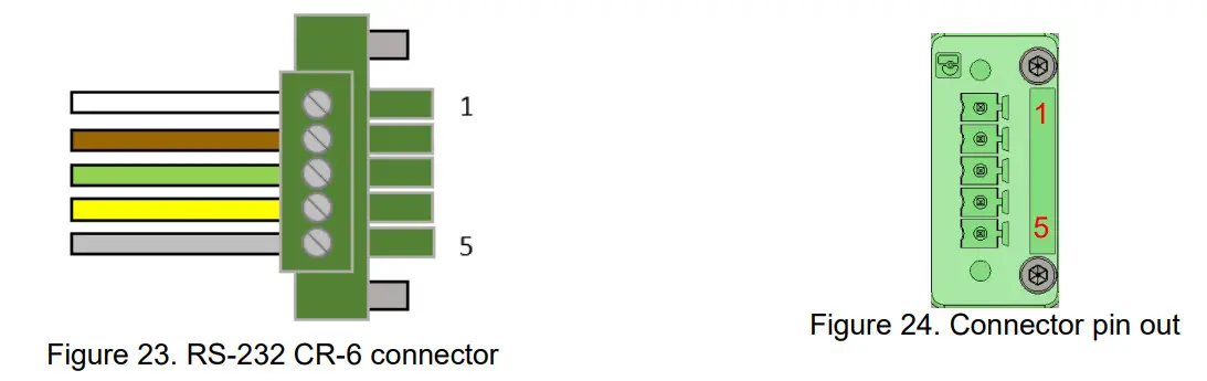
4.2.5.2. Mating Connector at the Instrument Side for RS-485 connection
Table 10. Electrical connections of an Instrument’s GPS device input connector
Pin | Signal | Standard Cable Colours | Comment |
| 1 | RX+ | White | 1 PPS signal from GPS |
| 2 | RX- | Brown | Transmit signal of GPS |
| 3 | GPS_1PPS | Green | Reception signal from instrument |
| 4 | V_EXT_GPS | Yellow | 12V power from instrument |
| 5 | GND_EXT | Grey | Ground from instrument |
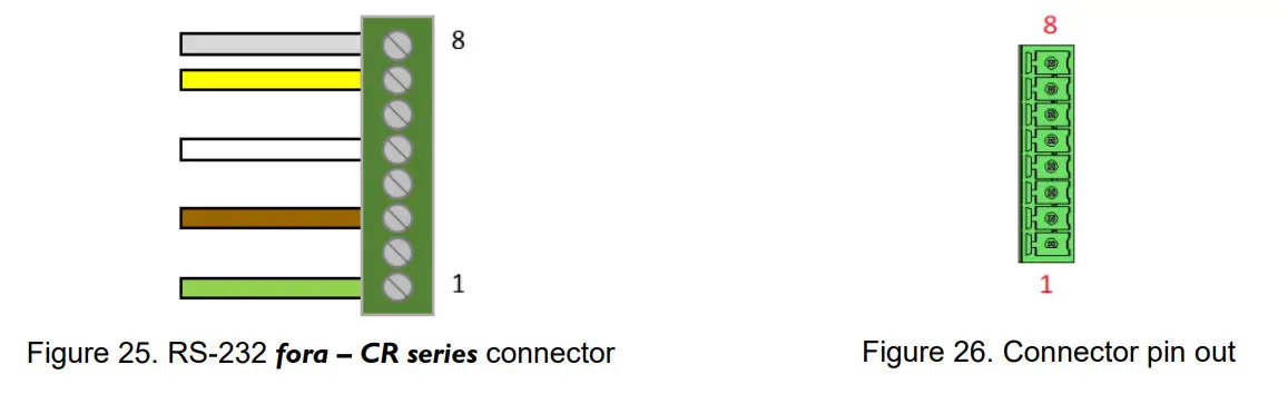
4.2.6. CR-7 / fora Device
4.2.6.1. Mating Connector at the Instrument Side for RS-232 connection
Table 11. Electrical connections of an Instrument’s GPS device input connector
Pin | Signal | Standard Cable Colours | Comment |
| 1 | GPS_1PPS+ | Green | 1 PPS signal from GPS |
| 2 | GPS_1PPS- | N/C | Not connected |
| 3 | TX+ | Brown | Transmit signal of GPS |
| 4 | TX- | N/C | Not connected |
| 5 | RX+ | White | Reception signal from instrument |
| 6 | RX- | N/C | Not connected |
| 7 | SUPPLY+ | Yellow | 12V power from instrument |
| 8 | SUPPLY- | Grey | Ground from instrument |
4.2.6.2. Mating Connector at the Instrument Side for RS-485 connection
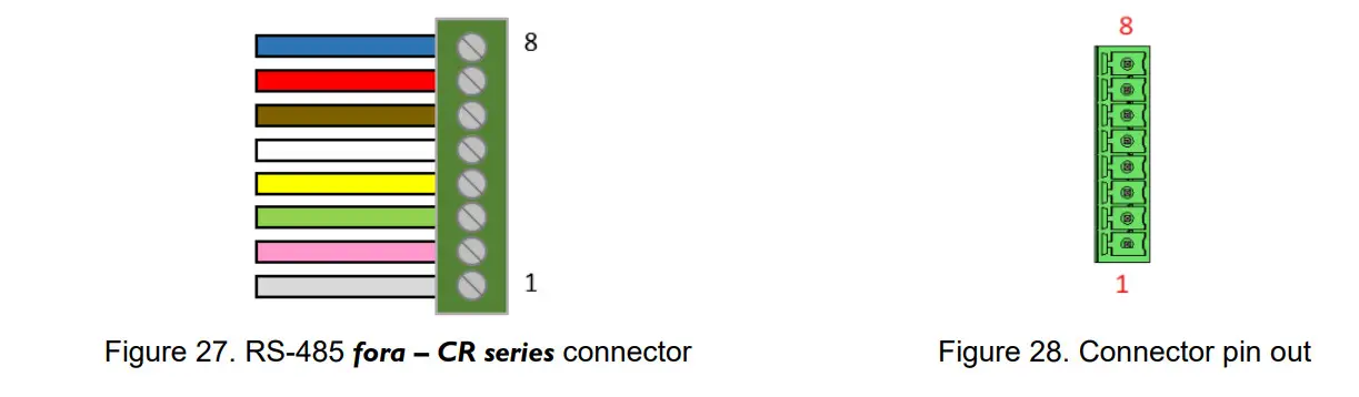
Table 12. Electrical connections of an Instrument’s GPS device input connector
| Pin | Signal | Standard Cable Colours | Comment |
| 1 | GPS_1PPS+ | Grey | 1 PPS signal from GPS (positive) |
| 2 | GPS_1PPS- | Pink | 1 PPS signal from GPS (negative) |
| 3 | TX+ | Green | Transmit signal of GPS (positive) |
| 4 | TX- | Yellow | Transmit signal of GPS (negative) |
| 5 | RX+ | White | Reception signal of GPS (positive) |
| 6 | RX- | Brown | Reception signal of GPS (negative) |
| 7 | SUPPLY+ | Red | Supply positive (12V power) |
| 8 | SUPPLY- | Blue | Supply negative (Ground) |
Configuration and Checking
5.1. With a GXR-XX
In order to synchronise a GeoSIG GSR-xx with the GPS, appropriate configuration should be made in the Instrument. Once power supply, computer and GPS are connected to the Instrument, such configuration and checks can be performed by logging into the Instrument using GeoDAS.![]() For more details about the GPS options, please consult GeoDAS and relevant Instrument manuals.
For more details about the GPS options, please consult GeoDAS and relevant Instrument manuals.![]() At first installation or after a major (>2’000 km) relocation, it may take up to 5 minutes for the GPS to correctly compute the exact location of the antenna.
At first installation or after a major (>2’000 km) relocation, it may take up to 5 minutes for the GPS to correctly compute the exact location of the antenna.
The following is a brief instruction to check whether everything is operational in terms of the GPS:
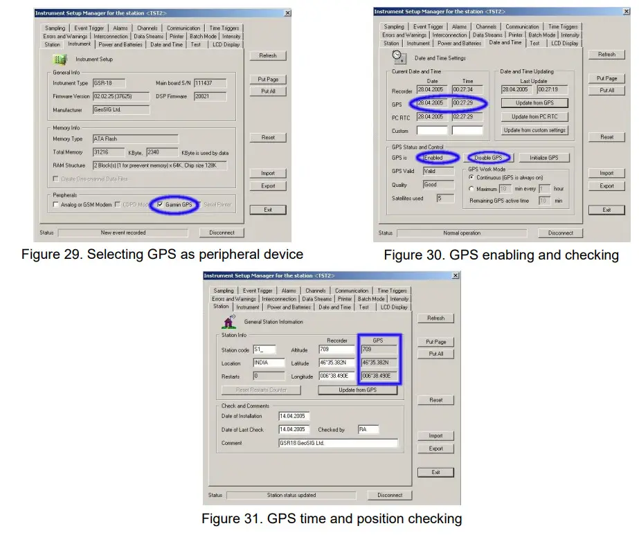
On “Instrument” tab, “Garmin GPS” option should be ticked as a peripheral device, as shown on Figure 29.
On the “Date and Time” tab, as shown on Figure 30, GPS status should read “Enabled”; if not, press the “Enable GPS” button.![]() Note that if GPS is enabled, this button reads “Disable GPS”.
Note that if GPS is enabled, this button reads “Disable GPS”.
When GPS is synchronised, the date and time of the GPS can be seen in the “Date and Time” tab and the global coordinates of the GPS antenna can be seen in the “Station” tab, as shown on Figure 31.
5.2. With a GMS-XX or a GMSplus or a SCAI or a NAIR
5.2.1. Configuration of GPS
In order to synchronise a GeoSIG GMS-xx or GMSplus with the GPS, appropriate configuration should be made in the Instrument. Once power supply, computer and GPS are connected to the Instrument, such configuration and checks can be performed by logging into the Instrument using GeoDAS.
In the Web Interface
- Go to Configuration
- In Data Acquisition tab go to Miscellaneous Parameters
- Go to Time synchronisation
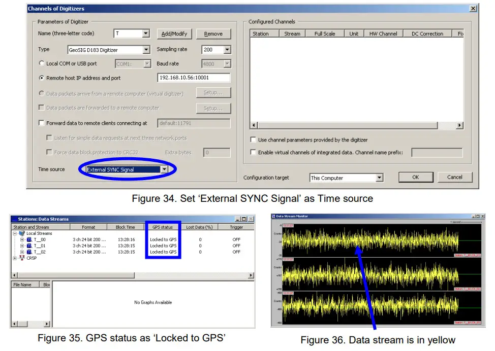
- In Time synchronisation menu shown in Figure 32, change the Time source to GPS
- Configure the options if necessary
- Finally click on Apply and Restart to apply the latest options to the device
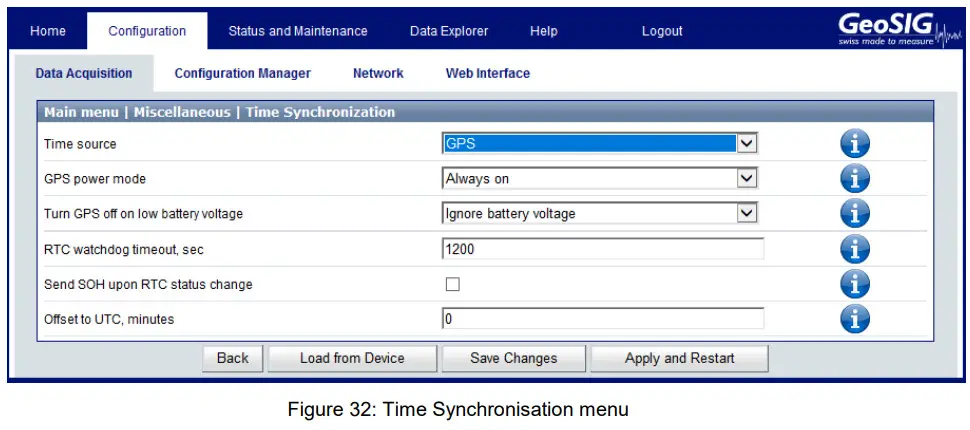
Some GPS options should be updated if necessary; the web interface offers some information about these options.![]() Click on this icon next to the option to see a summary of the option
Click on this icon next to the option to see a summary of the option
GPS configuration is explained in detail in the time synchronization subchapter of the User Manual.
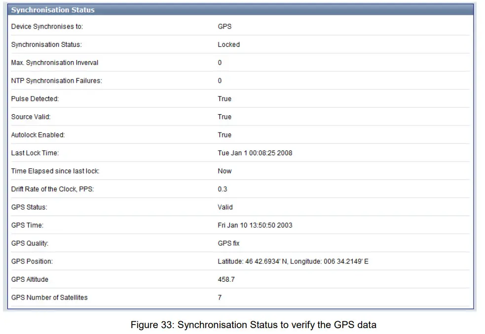
5.2.2. Check GPS data
In order to verify the GPS in a GeoSIG GMS-xx or GMSplus, appropriate configuration should be made in the Instrument. Once power supply, computer and GPS are connected to the Instrument, such checks can be performed by logging into the Instrument using GeoDAS.
In the Web Interface:
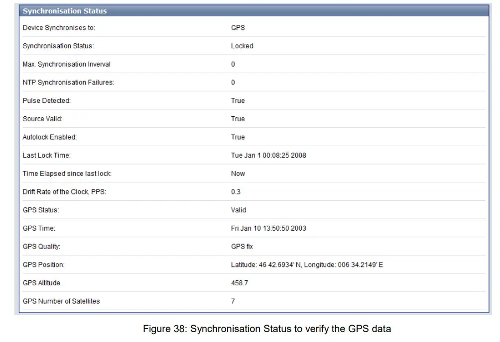
- Go to Status and Maintenance→ Recording Status tab
- Check data in the Synchronisation Status panel shown in Figure 33
5.3. With a CR-5P
In order to synchronise a GeoSIG CR-5P with the GPS, appropriate configuration should be made in the Instrument. Once power supply, computer and GPS are connected to the Instrument, such configuration and checks can be performed by logging into the Instrument using GeoDAS.
5.4. With a CR-6/CR-6plus or a CR-7 / fora
5.4.1. Configuration of GPS
In order to synchronise a GeoSIG GMS-xx or GMSplus with the GPS, appropriate configuration should
be made in the Instrument. Once power supply, computer and GPS are connected to the Instrument,
such configuration and checks can be performed by logging into the Instrument using GeoDAS.
In the Web Interface
- Go to Configuration
- In Data Acquisition tab go to Miscellaneous Parameters
- Go to Time synchronization
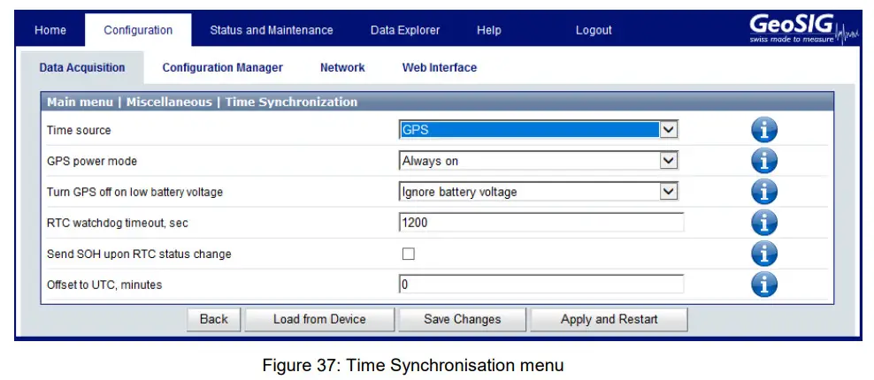
- In Time synchronisation menu shown in Figure 37, change the Time source to GPS
- Configure the options if necessary
- Finally click on Apply and Restart to apply the latest options to the device
Some GPS options should be updated if necessary; the web interface offers some information about these options.![]() Click on this icon next to the option to see a summary of the option
Click on this icon next to the option to see a summary of the option
GPS configuration is explained in detail in the Time synchronization subchapter of the User Manual.
5.4.2. Check GPS data
In order to verify the GPS in a GeoSIG GMS-xx or GMSplus, appropriate configuration should be made in the Instrument. Once power supply, computer and GPS are connected to the Instrument, such checks can be performed by logging into the Instrument using GeoDAS.
In the Web Interface:
- Go to Status and Maintenance→ Recording Status tab
- Check data in the Synchronisation Status panel shown in Figure 38