![]()
EFE Series Vertical Packaged Unit w/ Energy Recovery Ventilation
User Manual![]()
![]()
![]()
COPYRIGHT
First Co. works to continually improve its products and as a result, it reserves the right to change design and specifications without notice.
The warranty may be void unless the Startup & Performance Checklist is completed and returned to the warrantor. If the FRESH-PAK unit is not installed properly the warranty will be void as the manufacturer can’t be held accountable for problems that stem from improper installation.
©2021 First Co., 8273 Moberly Lane, Dallas, TX 75227
***WARNING TO INSTALLER, SERVICE PERSONNEL AND OWNER***
Altering the product or replacing parts with non-authorized factory parts voids all warranty or implied warranty and may result in adverse operational performance and/or a possible hazardous safety condition to service personnel and occupants. Company employees and/or contractors are not authorized to waive this warning.
SAFETY CONSIDERATIONS
- READ THE ENTIRE MANUAL BEFORE STARTING THE INSTALLATION.
- These instructions are intended as a general guide and do not supersede national, state, or local codes in any way.
- Altering the product, improper installation, or the use of unauthorized factory parts voids all warranty or implied warranty and may result in adverse operation and/or performance or may result in hazardous conditions to service personnel and occupants. Company employees or contractors are not authorized to waive this warning.
- This product should only be installed and serviced by a qualified, licensed, and factory authorized installer or service agency.
- All “kits”, parts, and “accessories” used must be factory authorized when modifying this product. Refer and follow instructions packaged with the kits or accessories when installing.
RECOGNIZE THE FOLLOWING SAFETY NOTATIONS THROUGHOUT THIS MANUAL AND POSTED ON THE EQUIPMENT:![]() WARNING
WARNING
indicates a potentially hazardous situation or unsafe practices that could result in severe personal injury or death and/or damage to property.![]() WARNING
WARNING![]() ELECTRIC SHOCK HAZARD
ELECTRIC SHOCK HAZARD
This warning signifies potential electrical shock hazards that could result in personal injury or death.![]() CAUTION
CAUTION
The CAUTION symbol indicates a potentially hazardous situation that may result in minor or moderate injury.![]() Important
Important
Suggests important procedure steps to insure proper installation, reliability, or operation.![]() Note
Note
Used to highlight suggestions, which may result in enhanced installation, reliability or operation.
MODEL NOMENCLATURE
 MODEL NUMBER DESCRIPTION – FRESH-PAK SERIES
Digit 1 – SERIES
- E – Eco Series
Digit 2 – UNIT TYPE
- F – Cooling with ERV
- P – Heat Pump with ERV
Digit 3 – HEAT TYPE
- E – Electrical Heat
- W – HW Coil
Digits 4-5 – NOMINAL COOLING CAPACITY
- 09 – 9,000 Btu/H
- 12 – 12,000 Btu/H
- 18 – 18,000 Btu/H
- 24 – 24,000 Btu/H
Digit 6 – VOLTAGE
- 2 – 208/230V
Digits 7-8 – HEAT TYPE (KW OR ROWS)
- 00 – No Heat
- 03 – 3kW
- 05 – 5kW
- 10 – 10kW
- 1R – 1 Row HW Coil
- 2R – 2 Row HW Coil
- 3R – 3 Row HW Coil
Digit 9 – REVISION LEVEL
A
Digits 10-11 – FUTURE USE
- 00 – Not Used
Digit 12 – CABINET / SLEEVE
- B – 20 x 26”
Digit 13 – ERV SUPPLY / HW CONNECTIONS
- R – Right
- L – Left
Digits 14-15 – OPTIONS
- 00 – None
DIGIT 16 – BRAND
- F – First Co.
GENERAL INFORMATION
![]() CAUTION
CAUTION
DO NOT use these units during any phase of construction. Mechanical components and filters can become clogged with dirt and debris, which can cause damage to the system.
The manufacture does not warrant equipment subjected to abuse. Construction debris can void warranties and liability for equipment failure, personal injury, and property damage.![]() WARNING
WARNING![]() ELECTRIC SHOCK HAZARD
ELECTRIC SHOCK HAZARD
Before servicing equipment, ALWAYS turn off all power to the unit. There may be more than one disconnect switch. Electrical shock can cause injury or death. All lockout tag out procedures should be followed.
Clear surrounding area of all tools, equipment, and debris before operating this unit.
These instructions are given for the installation of the Eco Series FRESH-PAK specifically. For any other related equipment, refer to the appropriate manufacturer’s instructions.![]() Important
Important
This furnace must never be operated under any circumstances without an air filter in place.![]() NOTE
NOTE
Material in this shipment has been inspected at the factory and released to the transportation agency in good condition. When received, a visual inspection of all cartons should be made immediately. Any evidence of rough handling or apparent damage should be noted on the delivery receipt in the presence of the carrier’s representative. If damage is found, a claim should be immediately filed against the carrier.![]() CAUTION Extreme caution must be taken that no internal damage will result from screws that are drilled into the cabinet.
CAUTION Extreme caution must be taken that no internal damage will result from screws that are drilled into the cabinet.
INTRODUCTION
The FRESH-PAK unit is a combination of our high efficiency, high performance and reliable vertically packaged unit with an integral Energy Recovery Ventilation (ERV) System. ERVs provide pre-conditioned fresh outdoor air to your space either directly or through the normal return of your air handling unit. The benefits include improved indoor airquality, reduced energy costs and lower first cost of installation. The FRESH-PAK, with available heat pump, comes standard with ECM blowers for high efficiency and comfort and features. All FRESH-PAK models are certified to AHRI Standard 390. The FRESH-PAK models are designed to operate with fluid temperatures between 50°F [10°C] to 110°F [43°C] in cooling mode and 50°F [10°C] to 90°F [32°C] in heating mode for continuous operation. These installation instructions are intended as a general guide only, for use by an experienced, qualified contractor.
STORAGE
Equipment should be stored in a clean dry, conditioned area with maximum temperatures up to 120°F [48.89°C] and minimum temperatures to 32°F [0°C]. Units should be stored upright and in an indoor environment. It is recommended to leave packaging on the unit until the installation is to begin.![]() WARNING
WARNING
Stacking of the FRESH-PAK systems is strictly prohibited. Failure to follow this directive may result in system and/or property damage. DO NOT operate these units during the construction process. Mechanical components and filters could become clogged with dirt and debris, which can cause damage to the system.
The manufacture does not warrant equipment subjected to abuse. Construction debris can void warranties and liability for equipment failure, personal injury, and property damage.
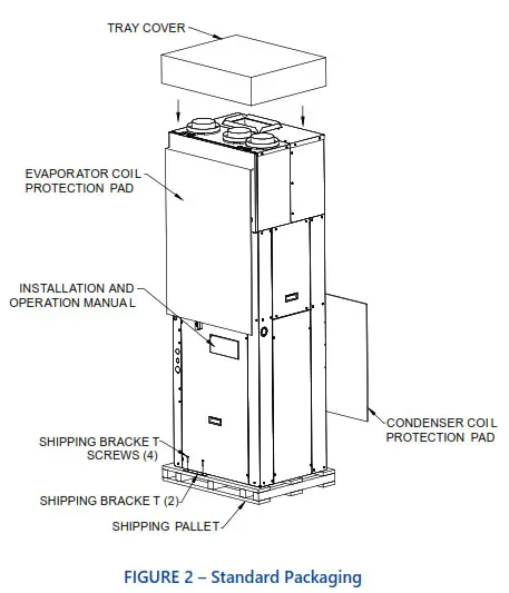
SHIPPING & PACKAGE LIST
![]() NOTE
NOTE
Material in this shipment has been inspected at the factory and released to the transportation agency in good condition. When received, a visual inspection of all cartons should be made immediately. Any evidence of rough handling or apparent damage should be noted on the delivery receipt in the presence of the carrier’s representative. If damage is found, a claim should be immediately filed against the carrier.
SHIPPING INSTRUCTIONS
FRESH-PAK units must remain in the upright position throughout the shipping and handling process to maintain a proper level of oil in the compressor.
PACKAGE LIST
The units will be shipped with the following:
- FRESH-PAK Package DX Cooling Unit with Integral ERV
a. Shipping brackets (2)
b. Screws (4)
c. Mounting bracket (2)
d. Screws (4) - Literature Package containing
a. IOM – Installation & Operations Manual - Duct Collar Kit
a. ERV Round Duct Connections (4)
b. Screws (12)
Check the unit for shipping damage; if found, immediately contact the last carrier.
UNIT INSPECTION CHECKLIST
Before preparing unit for installation, complete the inspection procedures below.
- Visually inspect unit for any shipping damage. Damage must be reported immediately to the shipping company to make a claim.
- Ensure that the carrier makes proper notation of any shortages or damage on all copies of the freight bill and completes a common carrier inspection report.
- Verify that unit nameplates on the data label match the sales order or bill of lading (including, unit configuration, size and voltage).
- Immediately before installation, remove unit front panel and verify that all electrical connections are tight and that there are no loose wires.
- Check to make sure that the refrigerant piping is free from any kinks and there is no interference between unit piping and sheet metal or electrical wires.
- Remove the blower access panel and remove the Styrofoam packaging mount underneath the blower.
- Check that the blower spins freely within the housing and there are no obstructions between the wheel and housing. The wheel can sometimes come loose in shipping.
- Ensure that evaporator distributor tubes are not touching one another and that they are over the drain pan.
- Check the air-coil fins for any damage during shipping.
- Ensure that shipping brackets and screws are removed from condensing section. Refer to FIGURE 3 – Standard Packaging with Brackets — Front View & FIGURE 4 – Standard Packaging with Brackets — Back View for more information.
 FIGURE 3 – Standard Packaging with Brackets – Front View
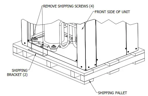 FIGURE 3 – Standard Packaging with Brackets – Front View
![]() NOTE
NOTE
Check the unit nameplate for correct voltage with the plans before installing the equipment. Also make sure all electrical ground, connections are made in accordance with local code. 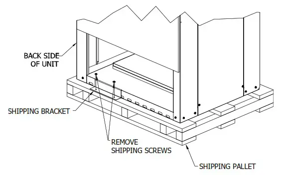
FIGURE 4 – Standard Packaging with Brackets – Back View
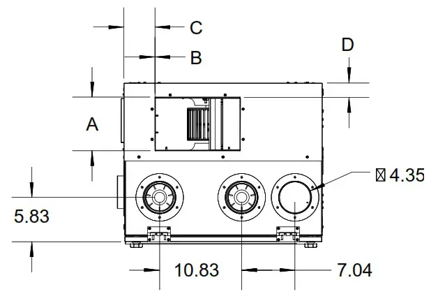
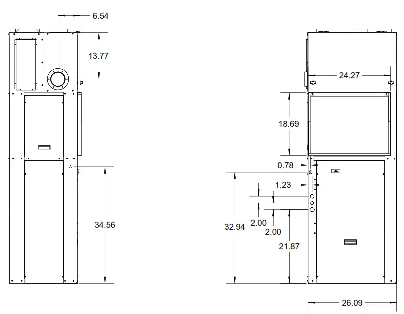
UNIT DIMENSIONAL DATA
| DIMENSIONAL DATA | ||||
| MODEL | A | B | C | D |
| SUPPLY CONNECTIONS | ||||
| 9 | 4 | 10 | 5.25 | 2 |
| 12 | 4 | 10 | 5.25 | 2 |
| 18 | 7 | 11.25 | 4.125 | 4 |
| 24 | 7 | 11.25 | 4.125 | 4 |
UNIT PHYSICAL DATA
| PHYSICAL DATA | ||||
| FRESH-PAK Model | 09 | 12 | 18 | 24 |
| Compressor (Quantity) | Rotary (1) | Rotary (1) | Scroll (1) | Scroll (1) |
| Factory Charge (R410A) lbs. [oz] | 3.40 [54.4] | 3.66 [58.6] | 4.80 [76.8] | 5.55 [88.8] |
| Fan Motor | ||||
| Motor (Quantity) | 1 | 1 | 1 | 1 |
| Fan Motor Type | ECM | ECM | ECM | ECM |
| Motor HP Standard / High Static | 1/4 | 1/4 | 1/3 | 1/2 |
| Blower | ||||
| Blowers (Quantity) | 1 | 1 | 1 | 1 |
| Blower Wheel Size (D x W) in. [cm] | 9 x 7 [22.86 x 17.78] | 10 x 7 [25.4 x 17.78] | ||
| Evap Coil | ||||
| Dimensions (H x W) in. [cm] | 18 x 22 [45.72 x 55.88] | |||
| Face Area ft² [m²] | 2.75 [0.26] | |||
| Miscellaneous | ||||
| Throwaway Filter Dim. in. [cm] | 18 x 24 [45.72 x 60.96] | |||
| Throwaway Filter Quantity | 1 | 1 | 1 | 1 |
| Operating Weight lbs. [oz] | 260 [4,160] | 260 [4,160] | 270 [4,320] | 310 [4,960] |
| Packated Weight lbs. [oz] | 285 [4,560] | 285 [4,560] | 295 [4,720] | 335 [5,360] |
| Notes: FPT = Female Pipe Thread | ||||
| Table 2 – Physical Data Table | ||||
ELECTRICAL DATA
| ELECTRICAL DATA | ||||||||||||||
| MODEL NUMBER | VOLTAGE-PH-HZ | COMPRESSOR | CONDENSOR MOTOR | BLOWER | ERV | MIN. CIRCUIT AMPACITY* | MAX. CIRCUIT PROTECTION* | MIN. VOLTAGE | MAX. VOLTAGE | |||||
| RLA | LRA | FLA | HP | FLA | HP | FLA | MIN | MAX | MIN | MAX | ||||
| EFE MODELS – COOLING ONLY | ||||||||||||||
| EFE092** | 208/230V-1-60 | 4.4 | 20.0 | 2.3 | 1/4 | 2.3 | 1/4 | .60 | 11 | 27 | 15 | 30 | 208 | 230 |
| EFE122** | 208/230V-1-60 | 4.7 | 25.0 | 2.3 | 1/4 | 2.3 | 1/4 | .60 | 12 | 31 | 15 | 35 | 208 | 230 |
| EFE182** | 208/230V-1-60 | 9.0 | 56.6 | 2.3 | 1/4 | 2.8 | 1/3 | .60 | 17 | 56 | 25 | 60 | 208 | 230 |
| EFE242** | 208/230V-1-60 | 10.9 | 61.6 | 2.8 | 1/3 | 4.1 | 1/2 | .60 | 22 | 58 | 25 | 60 | 208 | 230 |
| EFW MODELS – COOLING WITH HOT WATER | ||||||||||||||
| EFW092** | 208/230V-1-60 | 4.4 | 20.0 | 2.3 | 1/4 | 2.3 | 1/4 | .60 | 11 | 15 | 208 | 230 | ||
| EFW122** | 208/230V-1-60 | 4.7 | 25.0 | 2.3 | 1/4 | 2.3 | 1/4 | .60 | 12 | 15 | 208 | 230 | ||
| EFW182** | 208/230V-1-60 | 9.0 | 56.6 | 2.3 | 1/4 | 2.8 | 1/3 | .60 | 17 | 25 | 208 | 230 | ||
| EFW242** | 208/230V-1-60 | 10.9 | 61.6 | 2.8 | 1/3 | 4.1 | 1/2 | .60 | 22 | 25 | 208 | 230 | ||
| EPE MODELS – HEAT PUMP | ||||||||||||||
| EPE092** | 208/230V-1-60 | 4.4 | 20.0 | 2.3 | 1/4 | 2.3 | 1/4 | .60 | 11 | 27 | 15 | 30 | 208 | 230 |
| EPE122** | 208/230V-1-60 | 4.7 | 25.0 | 2.3 | 1/4 | 2.3 | 1/4 | .60 | 12 | 31 | 15 | 35 | 208 | 230 |
| EPE182** | 208/230V-1-60 | 9.0 | 56.6 | 2.3 | 1/4 | 2.8 | 1/3 | .60 | 17 | 56 | 25 | 60 | 208 | 230 |
| EPE242** | 208/230V-1-60 | 10.9 | 61.6 | 2.8 | 1/3 | 4.1 | 1/2 | .60 | 22 | 58 | 25 | 60 | 208 | 230 |
| NOTE: *Check nameplate for true unit MCA & MOP. | ||||||||||||||
| Table 3 – Electrical Data | ||||||||||||||
INSTALLATION
INSTALLATION PRECAUTIONS
![]() Caution
Caution
Always wear all appropriate personal protection Equipment when installing and servicing these units.![]() Warning
Warning
Use multiple people when moving and installing these units. Failure to do so could result in injury or death.![]() Caution
Caution
Contact with metal edges and corners can result injury. Protective gloves should be worn when handling. Exercise caution when installing and servicing unit.
Observe the following precautions for typical installation:
- Always use proper tools and equipment
- No wiring or any work should be attempted without first ensuring the unit is completely disconnected from the power source and locked out. Also, verify that a proper permanent and uninterrupted, ground connection exists prior to energizing power to the unit.
- Review unit nameplate and wiring diagram for proper voltage and control configurations. This information may vary from unit to unit.
- Units must be installed level or angled toward the drain nipple to ensure proper drainage and operation.
- Be sure that the drain pan is free from foreign material prior to start up.
![]() Caution When the unit is in operation components are rotating at high speeds and caution should be taken.
Caution When the unit is in operation components are rotating at high speeds and caution should be taken.
- Check filter media installation to ensure that it is installed correctly. Use the directional arrows or other information on the filter to determine the proper flow direction.
- Ensure air distribution system does not exceed the external static rating of the unit.
![]() Warning When soldering and brazing, it is recommended to have a fire extinguisher readily available. When soldering and brazing close to valves or sensitive components, heat shields or wet rags are required to prevent damage to the valves or components.
Warning When soldering and brazing, it is recommended to have a fire extinguisher readily available. When soldering and brazing close to valves or sensitive components, heat shields or wet rags are required to prevent damage to the valves or components.![]() NOTE
NOTE
Insulation is installed in the unit to provide a barrier between varying atmospheres outside and within the unit. If insulation is damaged condensation can occur and can lead to corrosion, component failure, and possible property damage. Damaged insulation must be repaired prior to the operation of the unit. Insulation will lose its effectiveness and value when wet, torn, separated, and/or damaged.![]() Caution When servicing this equipment, because of high pressures, make sure the reversing valve, expansion device, filter drier and other components are specifically designed for R-410A refrigerant. ONLY USE service equipment specifically designated for use with R410A.
Caution When servicing this equipment, because of high pressures, make sure the reversing valve, expansion device, filter drier and other components are specifically designed for R-410A refrigerant. ONLY USE service equipment specifically designated for use with R410A.![]() Warning R-410A can become combustible if mixed with air at elevated temperature and/or pressure. Failure to follow this warning could result in property damage and personal injury or death.
Warning R-410A can become combustible if mixed with air at elevated temperature and/or pressure. Failure to follow this warning could result in property damage and personal injury or death.
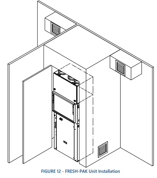
UNIT LOCATION
This FRESH-PAK unit is certified for through-the-wall, indoor, up-flow vertical position installation only. This appliance is not design certified for installation in mobile homes, recreational vehicles, or outdoors. A factory approved wall sleeve must be used to install the FRESH-PAK unit.
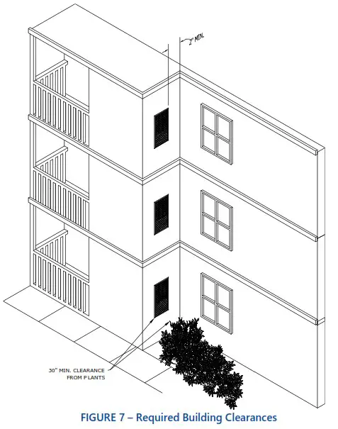
The interior portion of the unit is surrounded by a closet with a rear access, refer to FIGURE 6 – Condo with FRESH-PAK on Exterior Wall. The vertical discharge allows for ducting to the top of the room for best air circulation and elimination of cold drafts on occupants. The exterior (grille side) of the unit must have no obstruction (trees, landscape material, etc.) within 30 inches [76.2cm].
![]() NOTE
NOTE
Do not locate two units adjacent to each other on an inside corner or where they may exhaust into each other.
Provisions should be made to allow access to the indoor side of the unit for installation and inspection. The closet or access panel opening must be centered with the exterior wall opening and be at least 30 inches [76.2cm] wide by 84 inches [213.36cm] tall for all FRESH-PAK models.
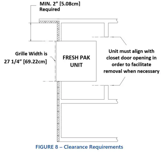
6 inches [15.24cm] (3 inches [7.62cm] on sides without the ERV fresh air connection) of unobstructed clearance must be maintained around the FRESH-PAK chassis for adequate airflow to achieve optimum performance. These guidelines address minimum spacing requirements only. It is acceptable to go beyond these limits at any time. At least 27 inches [68.58cm] of unobstructed space should be provided in front of the access door to permit removal of the unit, should repair and inspection be required.![]() NOTE
NOTE
The FRESH-PAK units are designed for quiet operation, however, all air conditioning equipment will transfer some amount of noise to the conditioned space. This should be taken into consideration when planning the location of the equipment.![]() NOTE
NOTE
Architectural Grille must be installed prior to the installation of the FRESH-PAK unit into the sleeve.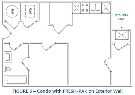
UNIT CLEARANCE REQUIREMENTS
The interior of the unit may be installed with zero clearances to adjacent combustible surfaces. This furnace shall not be installed directly on carpeting, tile, or other combustible material, other than wood flooring.
Service clearance must be provided for future maintenance and service. A minimum of 29” [73.66cm] open area must be left unobstructed in front of the access panels.
The grille side must be kept free from any obstructions to air flow. The unit must be installed at least 4 feet [1.22m] from electric meters, gas meters, regulators, and relief equipment. Products of combustion are discharged outside from the vent outlet located at the front grille; therefore all distances from adjacent public walkways, adjacent buildings, openable windows, and building openings must be compliant with those called for in the National Fuel Gas Code ANSI Z223.1 and/or CAN/CGA-B149 installation codes, as well as local codes.
| CLEARANCE REQUIREMENTS | ||
| MINIMUM CLEARANCE | INCHES | CM |
| Horizontal distance between units | 12 | 30 |
| Vertical distance between units | 60 | 152 |
| Distance above ground level | 6 | 15 |
| Distance above finished floor | 6 | 15 |
| Distance above a garage floor | 18 | 46 |
| Table 4 – Clearance Requirements | ||
A furnace installed in a garage must also be protected from damage by vehicles.
WALL SLEEVE INSTALLATION
Refer to installation instruction packed with the wall sleeve to assemble and mount into the wall. Before unit installation, make sure sleeve components are not damaged; drain line is not obstructed and is leak free. Check all seals to ensure that they are in position and undamaged. Ensure that the wall sleeve is sloped toward the exterior of the building Securely fasten the Architectural grille to the front of the sleeve using the supplied hardware. 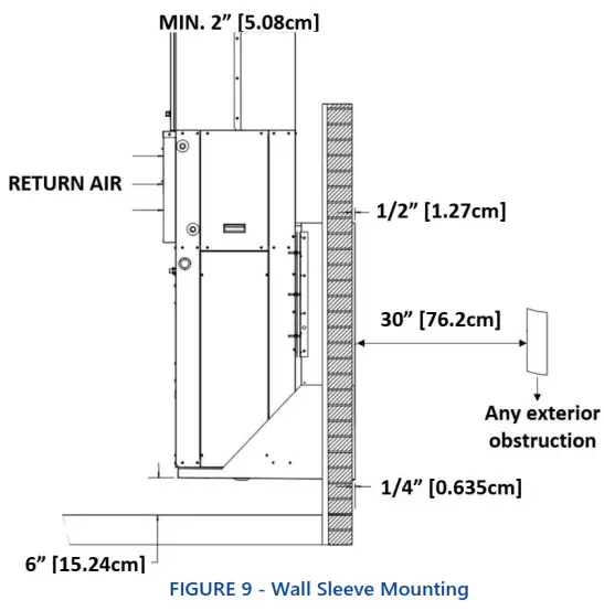
![]() Important
Important
After sleeve installation, ensure that the gap in-between the wall and seal is insulated and is in contact with the sleeve sides.![]() Important
Important
Make sure a high grade non-hardening sealant approved for exterior use has been applied between edge of the sleeve and the structure, on the inside and outside walls, to prevent air and water from migrating inside
REAR INSTALLATION & DIMENSIONS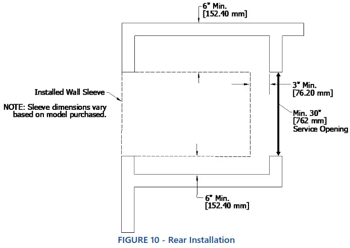
- Sleeve rough-in opening is 44” (H) [111.76cm] x 275/8” (W) [70.17cm].
- Bottom of opening should be approximately 6” [15.24cm] about the floor.
- Minimum of 6” [15.24cm] clearance is required on the ERV fresh air (supply air) side.
- Minimum of 3” [7.62cm] of clearance is required on all sides, except ERV fresh air (supply air) side, of the FRESH-PAK unit.
SIDE INSTALLATION & DIMENSIONS 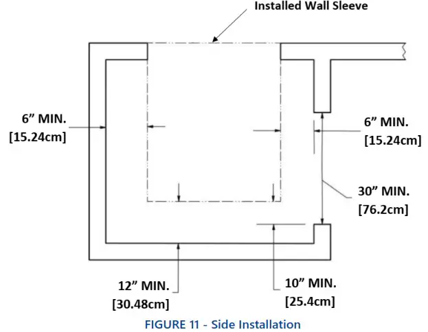
- Sleeve should be installed in exterior wall prior to constructing closet.
- Minimum Service opening is 30” (W) [76.2cm] x 84” (H) [213.36cm].
- Sleeve rough-in opening is 44” (H) [111.76cm] x 275/8” (W) [70.17cm].
- Bottom of opening should be approximately 6” [15.24cm] above the floor.
- Closet access must be situated in such a way that the ERV CORE can be removed while the unit is installed on the sleeve. Minimum of 10” [25.4cm]
see FIGURE 11 – Side Installation above.
![]() NOTE
NOTE
Sleeve dimensions vary based on model purchased.
PACKAGED UNIT INSTALLATION
![]() NOTE
NOTE
Locate the unit in an area that provides minimum clearance to all service access panels. Consider all additional clearances needed for water connections, electrical connections, duct connections and sufficient return airflow.![]() Important
Important
These units are for indoor installation ONLY!![]() NOTE
NOTE
Do not locate unit in areas subject to freezing temperatures or where high humidity levels could cause cabinet condensation. FRESH-PAK units are available in right and left hand configurations. Units should be mounted on the sleeve with a pitch to the outside of the building.
Insulation is installed in indoor equipment to provide a barrier between outside air conditions surrounding the unit and the varying conditions inside the unit. If the insulating barrier is damaged, the surrounding ambient air will affect the inside surface temperature of the cabinet; this may lead to sheet metal corrosion and subsequently, component
failure.![]() Important
Important
Damaged insulation must be repaired or replaced before the unit is placed back into operation. Insulation loses its insulating properties when wet, damaged, separated or torn.
The installer must adhere strictly to all local and national code requirements pertaining to the installation of this equipment. All units are designed for indoor use only, and are agency listed for installation with clearances specified in SECTION to combustible materials. This includes the cabinet, discharge plenum and connecting ducts.![]() NOTE Check nameplate voltage, amperage and fuse size for proper power supply.
NOTE Check nameplate voltage, amperage and fuse size for proper power supply.
PACKAGE UNIT INSTALLATION
- Remove the two shipping brackets holding the unit to the shipping pallet and remove unit from the shipping pallet.
 NOTE
NOTE
The top mounting bracket must be attached to the FRESH-PAK unit. - Ensure that properly sized ductwork is in place to mate to the connections on the FRESH-PAK.
- Before setting unit into closet, remove upper side access panel and inspect the evaporator blower to ensure that the wheel turns freely without rubbing on the housing. NOTE Remove the Styrofoam shipping block supporting the blower assembly.
- Replace upper access doors prior to completing installation.
- Remove the disconnect and the rear access door to get to the loose items described in the packing list. Check all electrical connections and check the condenser fan to see if it turns freely.
- Remove the 4 ERV duct collars from inside the cabinet.
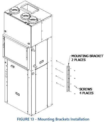
- Attach unit mounting brackets (2) as shown in FIGURE 13 – Mounting Brackets Installation.
 NOTE
NOTE
For shipping purposes the supply flanges are shipped flat. The discharge duct flanges must be bent up at a 90° angle. - Ensure that the wall sleeve is installed squarely and is secured before installing the unit. Important
After removing the construction debris guard, check the bottom of the sleeve pan to ensure that it is sloped toward the building exterior. Ensure that the bottom of the pan and drain are clear of obstruction and are operational. NOTE Inspect the sleeve seal, which is supplied with the sleeve, to ensure that it is properly secured and aligned. Use a high-grade non-hardening sealant to close any gaps that may exist between the seal and the wall of the sleeve. - After the seal is inspected, lift the unit onto the base of the sleeve and slide the unit forward to engage the seal. The unit uses locking brackets with weld studs. Align the unit to the bracket on the sleeve. Tighten down the unit until there is a tight seal with the sleeve. See FIGURE 14 – Wall Sleeve Seal.

- Check that the unit is completely seated on all four sides against the wall sleeve seals.
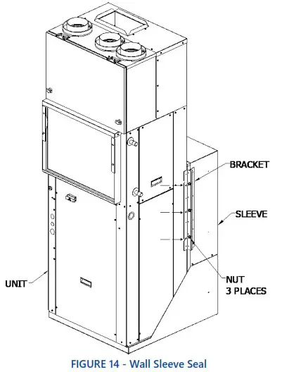
![]() CAUTION
CAUTION
If unit is not sealed properly, water and/or outside air will infiltrate into the closet, and can cause improper unit operation and may cause damage to the unit and/or property.
PIPING (HOT WATER COILS)
![]() CAUTION
CAUTION
Prior to making piping connections, contractor must clean and flush water loop system. Failure to clean/flush system may result in nuisance tripping and premature component failure.
PIPING NOTES
- Flush all field piping prior to connection to clear all debris.
- Open all valves (mid-way for hand valves, manually open motorized valves) prior to soldering and brazing. Use proper heat shields to protect valve bodies.
- When soldering or brazing to the unit, it is recommended to hava fire extinguisher readily available.
- Use proper soldering and brazing techniques to protect valve bodies and unit components.
- Heat can only be applied to the cup of the valve body for a minimal time before damage occurs (even with the use of wet rags).
- Avoid rapid quenching of soldered joints to prevent weakening.
- Make provisions for expansion and contraction of piping systems to provide movement with temperature changes. Failure to do so will result in damage and failure of piping, fittings, and valves throughout the system.
- DO NOT insulate the heads or motorized portion of control valves. Excessive heat build-up can cause damage and affect proper operation of the system.
- Consider electrical routing when installing field piping.
- Observe all regulations and codes governing installation of piping.
 CAUTION
Hydronic systems are not designed to hold pressurized air and should only be tested with water. Pressurizing system with air could damage equipment. - When all connections are complete, pressure test the system, and repair any leaks or faulty joints. Hydronic systems are not designed to hold pressurized air and should only be tested with water. Failure to observe this note could damage the system.
PIPING INSTALLATION:
- All piping must be adequately sized to meet the design water flow requirements as specified for the specific installation. Piping must be installed in accordance with all applicable codes.
- The piping connection on the equipment are not necessarily indicative of the proper supply and return line sizes. To minimize restrictions, piping design should be kept as simple as possible.
![]() CAUTION
CAUTION
Do not bend or kink supply lines or hoses. For all supply lines or hoses of 1-1/2” OD or greater, use proper sized fitting is recommended to prevent piping damage and potential restrictions in water flow.
- Prior to connecting the FRESH-PAK all external piping must be purged of debris.
- It is also recommended that all piping be insulated to prevent freezing when piping is run in all unconditioned spaces.
![]() NOTE
NOTE
Coil freeze protection is recommended for applications where the FRESH-PAK w/Hot Water is located in ambient air locations or within structures that may be unoccupied during freezing conditions. Consult the factory for additional information.
DUCTWORK
Discharge ductwork is normally used with these units. When return air ductwork is required, the unit is supplied with 2” [5.08cm] thick filter rack/duct collar for connection of return air ductwork. All ductwork must be installed in accordance with National Fire Protection Assoc. Codes 90A and 90B.
Supply and Return ducts must be sized properly as to not exceed static pressure capabilities of the unit. Ducts should be adequately insulated to prevent condensation and to minimize heat loss. A flexible connector is recommended for supply air connections on metal duct systems.
DISCHARGE DUCTING
All Ductwork must conform to industry standards of good practice as described in ASHRAE System Guide.
The transition piece from the unit discharge to the duct distribution system must not have an angle greater than 30° or severe loss of air performance can result. Do not connect the full duct size to the unit discharge collar without using a transition piece down to the size of the unit discharge collar. With metal material, the sides of the elbow and entire branch duct should be internally lined with acoustic insulation for sound attenuation.
The ductwork should designed so that there is no line of sight between the unit discharge and the distribution diffusers.
![]() NOTE
NOTE
Follow the filter rack kit instructions & recommendations for installation.
RETURN AIR DUCTING
Return air duct can be brought in through a wall grille and then to the unit. The return duct system will normally consist of flexible connector at the unit and a trunk duct to the return air grille. With metal duct material, the return air duct should be internally lined with acoustic insulation for sound attenuation.
A 2” [5.08cm] air duct collar flange is included on the filter rack for ducted return air application. A flexible duct collar can then be attached between a duct transition and the return air ductwork. The return air duct transition must be the same size as the return air coil face area. See FIGURE 15 – Ductwork. Be sure to allow for proper clearance to allow for filter change outs.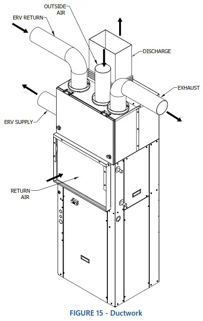
CONDENSATE DRAIN
The FRESH-PAK is designed so that the wall sleeve is the principle drain pan. Drain tubing is factory installed which drains evaporator condensate though the bottom of the unit which then is allowed to drain into the wall sleeve pan.
Condensate drain lines must be installed with adequate slope to ensure positive drainage.
Prior to unit installation ensure that the drain is unobstructed and leak free.![]() CAUTION
CAUTION
On units with plastic drain pans, the drain connection must be made hand tight only. 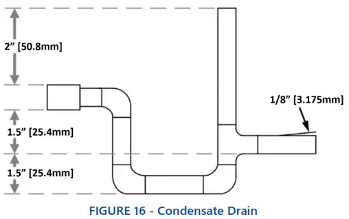
![]() NOTE
NOTE
When preparing unit for installation, check to ensure that the drain tubing from the evaporator is securely attached to the copper nipple in the pan under the compressor. The wall sleeve has a ¾” NPT nipple located in the bottom for connection to a drain (FIGURE 16 – Condensate Drain). A trap may be required in the condensate drain line to prevent sewer gas from escaping into the room.
AIR FILTER
All indoor return air must be filtered. The preferred methods are:
- Use the factory supplied filter kit which attaches to the inlet of the evaporator.
- Use the filter kit supplied with the access panel which accepts an 18 inch [45.72cm] x 20 inch [50.8cm] x 1 inch [2.54cm] (or 2 inch [5.08cm]) throwaway type of filter.
- Install a filter in the return grille mounted in the wall. Any field installation of an air filter, means must be provided, for us of a disposable filter which is no smaller than the face area of the evaporator coil.
![]() CAUTION
CAUTION
Do not operate this equipment without an air filter. 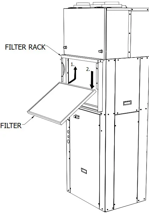
ELECTRICAL
HIGH VOLTAGE![]() WARNING
WARNING![]() ELECTRIC SHOCK HAZARD
ELECTRIC SHOCK HAZARD
Disconnect all power supplies before servicing. Lock out/tag out to prevent accidental electrical shock. NOTE: There may be multiple power sources supplying the unit.![]() WARNING
WARNING
Use copper conductors only. Install all parts and panels before operation of unit. Failure to follow these warnings can result in injury or death.
All wiring must comply with local and national code requirements. Units are provided with wiring diagrams and nameplate data to provide information required for necessary field wiring.
These units are provided with a class 2 transformer for 24VAC control circuits. Should any add-on accessory or component also have a class 2 transformer furnished, care must be taken to prevent interconnecting outputs of the two transformers by using a thermostat with isolating contacts.![]() WARNING
WARNING
Connect ground wire to ground terminal marked “GND”. Failure to do so can result in injury or death.![]() CAUTION
CAUTION
Any device that has been furnished by the factory for field installatiomust be wired in strict accordance with the associated wiring diagram. Failure to do so could damage components and void warranties.
208 VOLT OPERATION
All 208-240 Volt units are factory wired for 240 Volt operation. For 208 Volt operation, moving/changing/rewiring the line voltage tap on the 24 Volt control transformer is required. See note on unit wiring diagram for instructions.
| THERMOSTAT CONNECTIONS KEY | ||
| LETTER | COLOR | DESCRIPTION |
| C | BROWN | Transformer 24VAC Common |
| R | RED | Transformer 24VAC Hot |
| G | GREEN | Evaporator Blower |
| U | YELLOW | ERV Comfort Command |
| Y | BLUE | Compressor Contactor |
| W2 | BLACK | Auxiliary Heating |
| B | ORANGE | Reversing Valve (energized in cooling) |
| Table 5 – Thermostat Connections Key | ||
LOW VOLTAGE
THERMOSTAT
A 24 VAC Ventilation thermostat is required to operate the FRESH- PAK unit (FIGURE 18 – Ventilation Thermostat Connections). A minimum 24 VAC Heat Pump Thermostat is required with a fan signal (G) in all operating Modes (FIGURE 19 – Non-Ventilation Thermostat Connections). Thermostat connections and functions are as follows: 
![]() Important
Important
Connect ground wire to ground terminal marked “GND”. Failure to do so can result in injury or death.
THERMOSTAT INSTALLATION
The Thermostat should be located on an interior wall in a larger room, away from supply duct draft. Position the thermostat back plate against the wall so that it appears level and so the thermostat wires protrude through the middle of the back plate mounting holes and drill holes with a 3/16” bit. Install supplied anchors and secure plate to the wall. Thermostat wire must be 18 AWC wire.
CONTROLS
ECO SEQUENCE OF OPERATIONS – COOL MODE
ECO SEQUENCE OF OPERATIONS – HEAT MODE
ECO SERIES CONTROL MODULE
 POWER-UP
When power is first applied to the control, all timers are reset. The control will execute a random start delay before allowing normal operation of outputs, and a compressor anti short cycle delay (6 minute) before allowing the compressor output to be energized. While the control is operating, all of the inputs are continuously monitored for a change in the desired operating status.
RANDOM START DELAY
There will be a control random start delay which will vary from 10 to 60 seconds, which will be executed before energizing outputs when the control is powered up. All control outputs remain off during the random start delay, with the exception of the reversing valve, which directly tracks the “O” input at all times the control is powered.
ANTI-SHORT CYCLE DELAY
After any time the compressor output has been energized the control will execute a 6 minute anti short cycle delay from the time the compressor is de-energized, before allowing the compressor output to be energized again. A 6 minute anti short cycle delay will be present at control power up, before allowing the compressor output to be energized.
POWER INTERRUPTIONS
If the power to the control is interrupted for less than 100 milliseconds, the control shall resume operation at the same point in the timing cycle if the compressor output is not energized. Relays may temporarily drop out during the power interruption. Power interruptions greater than 100 milliseconds are to reset the control as a power- sequence.
If the power to the control is interrupted for more than 40 milliseconds with the compressor output energized, the compressor output will be de-energized, and the control will execute a short cycle delay before allowing the compressor to operate.
COOLING OPERATION
STEADY STATE COOLING
When the “W1/Y” input is present, and the “O” input is not present, and the compressor is not being held off by the anti-short cycle timer, the control will operate in steady
state cooling. In steady state cooling, the compressor and condenser fan are energized. After a 7 second delay the high speed evaporator fan is energized. If the W2 input is applied to the control, the first stage auxiliary heat output will be energized immediately and the second stage auxiliary heat output will be energized after 15 seconds. The compressor and condenser outputs will be shut off and the evaporator fan will switch to low speed. When the “W2” input is removed, both auxiliary outputs will be turned off immediately, and the control will return to steady state cooling mode, assuming the “W1/Y” input is still present. When the “W1/Y” input is removed, the compressor and condenser fan will be turned off immediately. The high speed evaporator fan will be turned off following a 45 second blower off delay.
LOW AMBIENT SHUTDOWN
When the control is operating in steady state cooling, and the “INDOOR” input is applied (temperature 30°F [-1] and below), the control will immediately de-energize the compressor and condenser fan. The high speed evaporator will be turned off following a 45 second blower off delay. The compressor will go into an anti-short cycle delay for 6 minutes.
LOW AMBIENT COOLING LOCKOUT
When the control is operating in steady state cooling and the “COOLING LOCKOUT” input is applied (Outside Temperature of 40°F [4.4°C] or less) the control will continue to operate for 10 minutes. After 10 minutes, if the “COOLING LOCKOUT” is still active the cooling operation will be locked out for 30 minutes and run high speed evaporator during the lockout. After 30 minutes the control will be returned to normal operation.
HEATING OPERATION
FIRST STAGE HEATING
When the “W1/Y” and “O” inputs are present, and the compressor is not being held off by the anti-short cycle timer, the control will operate in steady state heating. In first stage heating, the compressor, reversing valve and condenser fan are energized. After a 7 second delay the high speed evaporator fan is energized. When the “W1/Y” input is removed, the compressor, condenser fan, and high speed evaporator fan will be turned off immediately.
SECOND STAGE HEATING
When the control is operating in first stage heating, and the “W2” input is applied, the control will stage into second stage heating. The first stage auxiliary heat output will be
energized immediately, and the second stage auxiliary heat output will be energized after 15 seconds. The compressor and condenser outputs will be shut off and the evaporator fan will switch to low speed. When the “W2” input is removed, both auxiliary heat outputs will be turned off immediately, if the “W2” input is removed and the “W1/Y” and “O” inputs are still present, the auxiliary heat will continue to operate until the thermostat is satisfied.
DEFROST LOCKOUT
When the control has inputs for first or second stage heating, and the “OUTDOOR DEFROST” input is removed (switch opens), the compressor and condenser fan outputs are de-energized, and the evaporator fan switches to low speed. If the auxiliary heat outputs are not already active, and the evaporator fan switches to low speed. If the auxiliary heat outputs are not already active, the first stage of auxiliary heat is energized immediately, and the second stage is energized after 15 seconds. Any time the “OUTDOOR DEFROST” input is removed (switch opens), a six (6) hour timer is activated and the compressor and condenser fan will not operate until the time has expired. During the time the compressor and condenser fan are locked out, the auxiliary heat will be energized any time there is a “W1/Y” and “O” or a “W2” input.
NOTE
Compressor can still run in the cooling mode during the 6 hour lockout.
LOW AMBIENT HEATING LOCKOUT
When the control is operating in first stage heating and the “COOLING LOCKOUT” input is applied the control will continue to operate for 10 minutes. After 10 minutes, if the “COOLING LOCKOUT” is still active the first stage heating will be locked out for 30 minutes. During the 30 minutes auxiliary heat will be activated any time there is a thermostat call for heating. After 30 minutes the control will be returned to normal operation.
REVERSING VALVE OPERATION
The reversing valve output will be energized when the “O” thermostat input is active, and off when the “O” input is not present, regardless of the other controls inputs.
CONTINUOUS FAN OPERATION
If no other thermostat inputs are present, the low speed evaporator fan output will be energized when the “G” thermostat input is active. If either or both of the “W1/Y” or W2” inputs are present, the operation of the evaporator fan will be based upon those inputs, and the “G” thermostat input will be ignored. compressor and condenser fan and will only allow auxiliary heat operation. In the case of the “W2” input interrupting the compressor operation, the auxiliary heat will continue to operate until the thermostat is no longer calling for heat.
AUXILIARY HEATING OPERATION
THERMOSTAT CALL FOR AUXILIARY HEAT
If the “W2” thermostat input is present without a “W1/Y” input, the control will operate in the auxiliary heat mode. The low speed evaporator fan and the first stage auxiliary heat outputs will be energized immediately when the “W2” input is received. After a 15 second staging delay, the second stage auxiliary heat output will be energized. When the “W2” input is removed, all of the outputs will be turned off immediately.
If the “W2” thermostat input is present with a “W1/Y” input, the control will switch the system to auxiliary heat mode and will de-energize the compressor and condenser fan immediately.
LOW ROOM AMBIENT AUXILIARY HEAT
If the “RS” low room temperature input becomes active (switch closes), the control will operate in the auxiliary heat mode, regardless of any other control inputs. The low speed evaporator fan and the first stage auxiliary heat outputs will be energized immediately when the “RS” input is received. After a 15 second staging delay, the second stage auxiliary heat output will be energized. When the “RS” input is removed, all of the outputs will be turned off immediately.
FRONT DESK SHUTDOWN OPERATION
If the front desk shutdown input “FD” is removed (switch opens), operation based upon the “W1/Y”, “W2” and “G” thermostat input will be prohibited. Auxiliary heat operation based upon the low room ambient temperature input “RS” is the only heating or cooling operation that will be allowed. When the “FD” input is re-applied (switch closes), the control will return to normal operation based upon the thermostat inputs.
![]() NOTE
NOTE
From the Factory this will not shutdown the ERV. This will only shutdown the Heating/Cooling modes.
THERMOSTAT INPUT OPERATION (W1/Y, W2 & O)
If both “W1/Y” and “W2” thermostat inputs are active, the control will lock out or interrupt the operation of the
FIELD SPEEDUP MODE
The field speedup mode is entered by applying R (24VAC) to W1/Y (active) without “O” being active (Cooling Mode), and closing the cooling lockout sensor switch (24VAC
applied to the terminal). The field speedup mode is automatically canceled after 5 minutes. While in the filed speedup mode, control timings will be reduced as follows:
| Random Start Delay | 0 Seconds |
| Short Cycle Delay | 5 seconds |
| Cooling Blower off Delay | 0 Seconds |
| Auxiliary Heat Staging Delay | 1 Second |
ERV CONTROL MODULE
ERV CONTROL MODULE KEY
| INTERFACE | TYPE | NOTE |
| Ba, B2, B3, B4 | Analog Input 1: Resistor Nechako | Al |
| Xi, X2 | Analog Input 1: Measuring o—Ivo 2) Taco pulls (max. 3ooHz) | Al |
| X3 | Analog / Digital (Binary) Input 1: Measuring o—Ivo 2: Potential free contact (NO or NC) | AI, BI |
| A1, A2, A3, A4 | Analog Output 1: Signal o—avow | AO |
| X8 | Analog / Digital (Binary) Input 1: Resistor Nechako 2: Potential free contact (NO or NC) | AI, BI |
| Da, D2 | Digital (Binary) input 1: Potential free contact (NO or NC) | BI |
| Q1 Q2 Q3 , | Relay (Binary) Output 1: Potential free contact (NO) | BO |
| Y1 | Digital (Binary) / Analog Output trial VAC 1: Signal On/Off 2: Signal PWN (constant period) | BO, AO |
Table 6 – ERV Control MODULE KEY
![]() NOTE
NOTE
TO MAKE ERV CONTROL CHANGES CONNECT EITHER OPTIONAL WIFI KIT OR BACNET COMMUNICATION TO THE ERV.
ERV DEFAULT CONFIGURATION
The controller’s I/O are preconfigured for the following applications:
- Supply exhaust fan speed control
- Outside air damper control (on off)
- Contact input for rapid ventilation (Fan boost) and occupied operating mode
- Common alarm output
DEFAULT ERV CONFIGURATION
| PIN | DESCRIPTION | BACNET OBJECT | SIGNAL TYPE | NOTE |
| B1 | Outside air temperature | Toga | NTC10k | |
| B2 | Supply air temperature | Tsum | NTC10k | |
| B3 | Exhaust air temperature | The | NTC10k | |
| B4 | Extract air temperature | Text | NTC10k | |
| D1 | Rapid ventilation input | RpdVntln | Contact | NO |
| D2 | Input room operating mode Comfort | OpModRin | Contact | NO |
| X1 | Supply air fan speed feedback voltage | FanSuSpdFb | 0—10V | |
| X2 | Exhaust air fan speed feedback voltage | FanSuSpdFb | 0—10V | |
| X3* | None | – | – | |
| X8* | None | – | – | |
| Q1* | None | – | – | |
| Q2 | None | – | – | |
| Q3 | Outside air damper command | DmpOaCmd | Relay | |
| A1 | Supply air fan speed | FanSuSpdFb | 0—10V | |
| A2 | Exhaust air fan speed | FanEhSpd | 0—10V | |
| A3 | None | – | 0—10V | |
| A4 | None | – | – | |
| Y1 | None | – | – |
*Not active from the factory will require field configuration
Table 7 – Default ERV Configuration
ERV Modes of Operation
| OPERATING MODE | CATEGORY | OPERATING VIA | DURATION | ACTIVATION SIGNAL |
| Protection | Off mode | APP, DI | Permanent | |
| Unoccupied | Normal or away mode | APP, POS8, DI | Permanent or TSP | |
| Economy | Normal mode | APP, POS8, DI | Permanent or TSP | |
| Comfort | Normal or Home mode | APP, POS8, DI | Permanent or TSP | |
| Fan boost (Rapid ventilation) | Temporary mode | APP, POS8, DI | Temporary | Continuous or pulse signal (duration can be parameterized) |
Table 8 – ERV Modes of Operation
ERV DEFAULT CONFIGURATION
OPERATING MODE CATEGORIES
The following selectable operating modes belong to operating mode categories.
NORMAL MODES
The normal modes Unoccupied, Economy, and Comfort are the main operating modes that can be applied for a constant and, if desired, infinite time. For each one, certain settings are defined, which sensibly apply to the corresponding state of the system.
- Unoccupied – the building is unoccupied and the system is operated with the most essential settings needed.
- Economy – The building is occupied, but the system is operated with economical, energy efficient settings
- Comfort – The building is occupied and the system is operated according to the needs of the user.
TEMPORARY MODES
The modes Fan Boost, is a temporary mode that can only be activated for a certain, settable time.
The temporary mode is activated either via POS8.44X0 or configured digital input as an impulse button or, when pressed longer, as an “egg
timer”.
Once activated, they override all normal operating mode and for the set time, the dedicated settings for the temporary mode apply, which mostly concerns the fan speed.
SIGNAL FOR FAN BOOST
- If the duration of the signal is <5 seconds:
The Signal is interpreted as an impulse: The temporary mode is started and only stopped when the timer has expired. - If the duration of the signal is >5 seconds:
The signal is interpreted as an “egg timer”: Temporary modes is started when the signal is activated and stopped when the signal is inactive.
OFF MODE
The operating mode Protection switches the system into a form of “Off” mode in which the fans no longer run. However, the system is not switched off completely, individual pumps can continue to operate and the frost protection strategy continues to run for as long as has been set.
The Protection mode can only be set in the configuration and cannot be set by the end user themselves (neither via app nor POS8.44×0)
OPERATING MODE SETTING
The settings for the operating modes define the specific settings for the supply and exhaust fans for all operating modes and for the speed and flow control strategies. These settings are configured by the installer. The end user has no option to change the values for the operating modes.
For Comfort, Economy, and Unoccupied modes, dedicated settings for temperature can be defined.
The temporary operating modes Fan Boost, In-room-sensor, have no dedicated temperature settings. For these modes, the settings of Comfort mode apply.
FAN SPEED CONTROL
Supply fan and exhaust fan set points have defined setting for each operating mode level. Individual percentage value is used between 0–100%.
These settings only define the fan speed used in various operating modes and they have no effect on other functions like deicing.
During active temperature control, values set here are used as maximum speed (80%). Depending on deviations to set point, temperature control can freely increase/decrease the speed of both fans simultaneously with symmetrical control signal which then keeps the set supply/exhaust ratio in every situation.
FAN BOOST
The Fan Boost mode can be activated as a temporary mode to temporarily increase ventilation, e.g. after a bath or in a sauna. In this case, Fan boost is activated directly and kept active until the set time has elapsed.
The Fan boost mode uses the fan speeds defined for the Comfort operating mode.
PASSIVE HEAT EXCHANGER, UNCONTROLLED
(PLTHEXG22Y)
The purpose of energy recovery is to absorb heat/cold from the exhaust air and transfer it back to the supply air side.
The control of the energy recovery is not possible, the ERC always works with maximum capacity. With this solution, the outside air cannot be used for heating or cooling even if the outside air is closer to the set point than the exhaust air (e.g. in rooms with a high internal load or when heating up after cold nights.)
C DE-ICING (PASSIVE, UNCONTROLLED)
Passive Energy Recovery units are basically just heat exchangers. They receive warm and humid air on one side and cold on the other which will eventually cumulate ice on the surfaces when the conditions are suitable for that. Passive element usually starts to cumulate ice close to 32° F [0° C].
ERV DEFAULT CONFIGURATION
DETECTING ICE ON THE HEAT EXCHANGER OR IN THE DUCT WORK
Detecting ice on the heat exchanger or in the ductwork is possible.
- With exhaust air temperature sensor The. This is not a real indication, but an expectation that ice is expected to build up.
- Deicing with The sensor starts with The is below the limit.
- The end of the de-icing phase cannot be detected and is estimated via timer.
- With outside air sensor Toga. This is used when no exhaust air sensor are available. It is also only an expectation that ice has built up.
- De-icing with Toga sensor starts when the Toga is below the limit.
- The end of the de-icing phase cannot be detected as is estimated via timer.
DE-ICING THE HEAT EXCHANGER
De-icing is possible by:
- Reducing the supply fan speed, so that the load of cold air incoming is reduced, increasing the exhaust air temperature.
- Preheating the outside air, increasing the exhaust air temperature.
DE-ICING MODES
The de-icing mode can be configured as:
- No De-icing
- Reduce fan speed
- Increase preheating
- Reduce fan speed and increase preheating
Deicing with fan speed is running in parallel or with 2 stage, see below.
TIME BASED DE-ICING STARTED BY TEh OR TOa
The sensor is not suitable for detecting the end of the de-icing phase.
Therefore, a fix de-icing time is used. After de-icing is finished, an off time is started until the next de-icing phase can be started again. The duration of the off time depends on the measured temperature at the start of the de-icing phase. De-icing time, maximum off time with assigned temperature and minimum off time with assigned temperature can be configured.
DE-ICING WITH REDUCED FAN SPEED STARTED BY TEh OR TOa
The temperatures have 2 adjustable limits. The limit SpTDeicFan(stage 2) starts de-icing with the fan speed. During deicing, fan speed for supply fan and exhaust fan are reduced to configurable values. For faster de-icing, it is possible to set supply fan speed set point even to 0%. In this case electric heaters in the supply air are blocked.
ERC SUPERVISION (PASSIVE, UNCONTROLLED)
A mechanical failure on the ERV (heat exchanger dirty etc.) can be detected via the efficiency of the heat exchanger. Therefore, the temperature difference between extract air / room air and exhaust air is used. When the difference drops below set value and stays below during set delay time, alarm is generated.
Detection function is active only when temperature difference between outside air and extract air is more than set limit.
When extract air temperature and exhaust air temperature are not available, the supervision of the ERV is not possible.
PRIORITY LIST
Different functions require priorities over the other functions so that logical/critical operation can be guaranteed.
- Safety functions (field configured)
- Off by smoke detector, emergency, supply air temperature or extract air temperature
- Off by fire damper closed
- Purge or smoke extract by smoke detector
- Protection functions
- A-Alarms for plant protection
- ERC de-icing function
- Switch or push button operations
- Rapid ventilation mode (Configured B1, POS8)
- Comfort mode (Conf. B1), Fireplace (Conf. B1), Off mode (Conf. B1), Eco mode (Conf. B1)
- Maintenance function
- User operation
- Present / Away button
- Manual operation
- Automatic Function
- Scheduler operation mode
OUTSIDE AIR DAMPERS (DMPSHOFFOA11Y)
When ventilation is active the outside air dampers are always open.
Damper(s) are controlled open/close from one binary output.
Delay time for outside air damper opening can be defined to secure that damper is fully open before fans are started.
STARTUP / SHUT-DOWN SEQUENCE
For safe and optimum operation of the ventilation unit, special switching and switch-off sequences are used to switch the ventilation off and on again.
The ventilation unit is normally not “switched off”, but can be switched off for maintenance work or in emergency situations. This can be done by opening the ERV maintenance panel releasing the door switch signal or by powering down whole FRESH-PAK system. The start –up sequence is used every time except in emergency situations. The start-up sequence applies also for fire damper test function which is performed automatically.
STARTUP SEQUENCES:
- Start is initiated.
- Only after power return. Delay time step 2 (to secure startup time for valves, fire dampers and ERC)
- If available open the outside air dampers. Delay time step 3 (to secure dampers fully open). If damper output cannot be switched, an A-Alarm is activated, the startup process is stopped.
- ERC ramps up to maximum speed. Heat exchangers bypass closes. Exhaust fan starts and ramps up to comfort mode speed. If exhaust fan speed is monitored, and the feedback signals is not received within the delay time, an A-Alarm is activated, the starting process is stopped. Delay time step 5 (to secure “heating up” of heat exchanger)
- Supply fan starts and ramps up to “unoccupied” mode speed Delay time step 6. If supply fan speed is monitored, and the feedback signal is not received within the delay time, and AAlarm is activated, the starting process is stopped.
- Both fans ramp to required operating mode speed. Delay time step 6 preparing for normal operation.
- Normal operating mode is started.
SHUTDOWN SEQUENCES:
Executed after normal operation or if startup is interrupted after step 4 is finished. Shutdown sequence is not used in emergency situations.
- Shutdown is initiated.
- Both fans ramp down to stop.
- Close the outside air dampers, same time as in start-up step 5.
- Plant is “Off”.
![]() NOTE
NOTE
The ERV portion of the FRESH-PAK can be switched off using the BACnet. The stop sequence is executed by activating the input PrtOpModRln or the BACnet object PitShD. These functions override all other influences except the emergency control and protection control.
ERV ALARM FUNCTIONS
GENERAL
The application uses 2 different alarm classes:
An A-Alarm indicated as important and urgent situation. IF an A-Alarm is triggered, the unit shuts down. An A-Alarm must be acknowledged and can only be reset after cause of alarm is eliminated.
A B-Alarm indicates a less urgent maintenance incident and during active B-Alarm, the unit runs either normally or is still in acceptable conditions to run (without major problems).
The installer can configure alarm for certain errors and can chose between A-Alarm, B-Alarm or no alarm.
Alarms must be acknowledged and as soon as the cause for each alarm is eliminated, normal operation is resumed. If one or more reasons still exist, acknowledgement does not rest that specific alarm and operation might not continue normally.
All alarms are shown with a time stamp and entry to nonvolatile storage for each “change of state”.
5 different alarm state are used in the application and they are valid for both A and B-alarms. These different states are meant to give additional information for different users and different situations. Relay operation is depending on actual configuration.
![]() NOTE
NOTE
For more Alarm details see Troubleshooting section.
For more information on ERV Alarm Function please see TROUBLESHOOTING Section Pages 42 & 43.
BLOWER SPEED CONTROL
FRESH-PAK units are equipped with a direct drive ECM blower motors.
See Table 9 – FRESH-PAK Blower Data for airflow at different external static pressure. Select the motor speed according to the airflow and external static pressure. See wiring diagram located on unit.
For FRESH-PAK models, the default motor tap selections can be changed by directly changing the speed tap at the motor terminal.
BLOWER DATA
| BLOWER DATA | FACTORY BLOWER SETTINGS | ||||||||||
| MODEL NUMBER | MOTOR TAP | FAN TORQUE | FAN SPEED | IWC STATIC PRESSURE | HOT WATER | ||||||
| 0. | 0.5 | COOLING | |||||||||
| EPEo92 | T3 | 30 | HIGH | 419 | 400 | 381 | 359 | 340 | |||
| T2 | 25 | MEDIUM | 383 | 36S | 341 | 321 | 299 | X | |||
| T1 | 22 | LOW | 361 | 344 | 317 | 297 | 274 | X | X | ||
| EPE122 | T3 | 35 | HIGH | 455 | 435 | 421 | 398 | 381 | |||
| T2 | 33 | MEDIUM | 440 | 421 | 405 | 382 | 364 | X | X | ||
| Ti | 25 | LOW | 383 | 365 | 341 | 21 | 299 | X | |||
| EPE182* | T4 | HIGH | |||||||||
| T3 | MEDIUM-HIGH | ||||||||||
| 12 | MEDIUM | ||||||||||
| Ti | LOW | ||||||||||
| E PE 242* | T4 | HIGH | |||||||||
| T3 | MEDIUM-HIGH | ||||||||||
| T2 | MEDIUM | ||||||||||
| T1 | LOW | ||||||||||
| Airflow data shown is with a dry col at 70°F DB EAT and with standard a” filter. *TBD | |||||||||||
Table 9 – FRESH-PAK Blower Data
![]() WARNING
WARNING![]() ELECTRIC SHOCK HAZARD
ELECTRIC SHOCK HAZARD
High efficiency brushless DC motors are wired with power applied at all times, see illustration above. Low voltage thermostat demand and board algorithms will control its use.
FIELD ERV ACCESSORIES
FIELD ERV ACCESSORIES CONNECTIONS
INSTALLATION![]() IMPORTANT Must be Manufacturer approved.
IMPORTANT Must be Manufacturer approved.
OUTSIDE AIR DAMPER
The FRESH-PAK ERV control allows for the addition of a motorized outside air damper. This is to help prevent any back draft air from entering the space while the ERV is not operating.
![]() NOTE
NOTE
Damper must be 24V and normally closed.
- Power down FRESH-PAK unit.
- Attach 24V lead to Q3 (See FIGURE 26 – Outside Air Damper Connection) on the ERV control board.
- Connect the Com lead of the damper to a chassis ground of the FRESH-PAK unit.
- Power on the FRESH-PAK unit.
- Once the ERV restarts (about 1-2 minute delay) verify that the damper opens.
BOOST TIMER
The FRESH-PAK ERV controller has the flexibility to work with many different wall mounted boost timers (egg timer).
For typical analog (rotary style) timers follow Version 1 installation method. For digital (120V wall style) follow Version 2 installation.
VERSION 1 (ANALOG)
- Power down FRESH-PAK unit.
- Find the 120V relay in the FRESH-PAK control box. Refer to the wiring diagram (Page 36). And remove the 24V leads from the relay.
- Connect the transformer side 24V lead to the LINE side of you timer switch.
- Connect the LOAD side of the timer switch to the D1 terminal wire [See FIGURE 27 – Version 1 (Egg Timer/Analog Connection)].
- Reenergize the FRESH-PAKunit.
- Once the ERV restarts (about 1-2 minutes) activate the timer and confirm the ERV fans go to high speed “Comfort Mode”.
VERSION 2 (DIGITAL)
- Power down FRESH-PAK unit.
- Refer to the Installation instructions provided with the 120V digital timer switch.
- Find the 120V relay in the FRESH-PAK control box. Refer to the wiring diagram (Page 36).
- Connect the LOAD side of the timer switch to the 120V pole on the relay.
- Connect the NEUTRAL side of the timer switch to the remaining pole on the 120V relay (FIGURE 28 – Version 2 (120V Digital Timer Connection)).
- Reenergize the FRESH-PAK unit.
- Once the ERV restarts (about 1-2 minutes) activate the timer and confirm the ERV fans go to high speed “Comfort Mode”.
LOCATION OF MAJOR COMPONENTS
WIRING DIAGRAMS
WD85X001 ERV WIRING DIAGRAM
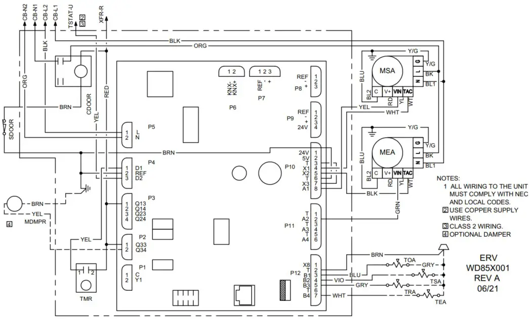
FIGURE 30 – WD85X001 ERV Wiring Diagram
WD85X004 9 & 12 FRESH-PAK HP 240V, 1 Element
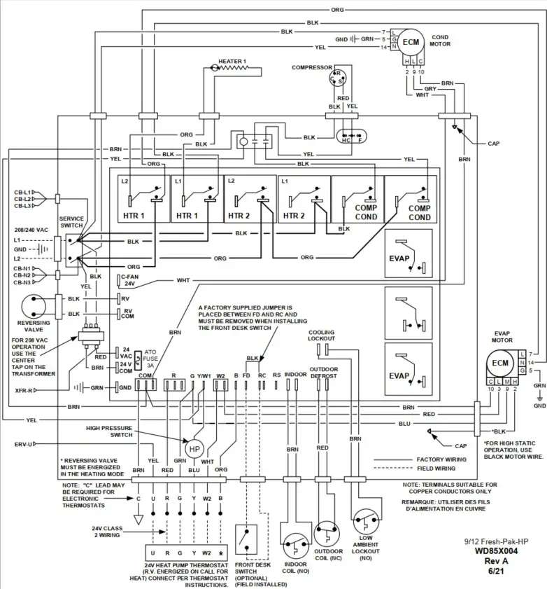
FIGURE 31 – WD85X004 9 & 12 Wiring Diagram
WD85X010 18 & 24 FRESH-PAK HP WITH 2 ELEMENTS
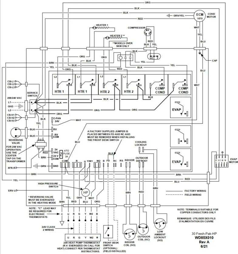
FIGURE 32 – WD85X010 Wiring Diagram
CIRCUIT SCHEMATIC
HEAT PUMP
COOLING & HOT WATER ONLY
STARTUP INSTRUCTIONS
PRE-STARTUP CHECKS:![]() WARNING
WARNING
Electrically ground the unit. Connect ground wire to ground lug. Failure to do so can result in injury or death.
![]() CAUTION
CAUTION
Wire any field installed device such as a fan switch or thermostat furnished by the factory in strict accordance with the wiring diagram supplied with the unit. Failure to do so could result in damage to components and will void all warranties.
Before start-up, thoroughly check all the components. Optimal operation of equipment requires cleanliness. Often after installation of the equipment, additional construction activities occur. Protect the equipment from debris during these construction phases.
PRIOR TO THE STARTUP OF THE UNIT:
- Ensure supply voltage matches nameplate data.
- Ensure the unit is properly grounded
- With the power off, check blower wheel set screws for proper tightness and that the blower wheel rotates freely.
- Ensure unit will be accessible for servicing.
- Ensure condensate line is properly sized, run, trapped, pitched and tested.
- Ensure all cabinet openings and wiring connections have been sealed.
- Ensure clean filters are in place.
- Ensure all access panels are in place and secured.
- Check that the water coil and piping had been leak checked and insulated as required.
- Ensure that all air has been vented from the water coil.
- Make sure that all electrical connections are tight and secure.
- Check the electrical overcurrent protection and wiring for the correct size.
- Verify that the low voltage wiring between the thermostat and the unit matches the wiring diagram.
- Verify that the water piping is complete and correct.
- Check condensate overflow sensor for proper operation and adjust position if required.
FRESH-PAK COOLING/ELECTRIC HEAT UNITS:
- Set thermostat system switch to “OFF” position and fan switch to “Auto” position. Apply power to the FRESH-PAK Unit. NOTE
The FRESH-PAK employs a random reset timer which delays unit operation up to 60 seconds following initial power application.
Electronic thermostats may also employ internal reset timers which may further delay any changes which are made to the operation of the unit. - Set fan switch to “On”, indoor blower should operate after the reset timer cycle is complete.
- Return fan switch to “Auto”, indoor blower should deenergize.
- Set system switch to “Cool” and lower the thermostat set point to coldest setting. The compressor should energize as well as the outdoor fan and indoor blower. NOTE
The FRESH-PAK employs a compressor short cycle delay (~6minutes) which will not allow the compressor to immediately restart following shut down. Additional delays may be experienced if using an electronic digital thermostat. - Return thermostat set point to a temperature warmer than a room temperature and the compressor and outdoor fan should de-energize. The indoor blower should remain in operation for an additional 45 seconds, then de-energize.
- Move system switch to “Heat” and raise thermostat to a set point higher than room temperature. The indoor blower and electric heating element(s) should energize.
- Return system switch to “Off” position.
FRESK PAK HEAT PUMP UNITS:
- Set thermostat system switch to “OFF” position and fan switch to “Auto” position. Apply power to the FRESH-PAK Unit. NOTE The FRESH-PAK employs a random reset timer which delays unit operation up to 60 seconds following initial power application. Electronic thermostats may also employ internal reset timers which may further delay any changes which are made to the operation of the unit.
- Set fan switch to “On”, indoor blower should operate after the reset timer cycle is complete.
- Return fan switch to “Auto”, indoor blower should deenergize.
- Set system switch to “Cool” and lower the thermostat set point to coldest setting. The compressor should energize as well as the outdoor fan and indoor blower.
FRESK PAK HEAT PUMP UNITS: - Return thermostat set-point to a temperature warmer than room temperature and the compressor and outdoor fan should de-energize. The indoor blower should remain in operation for an additional 45 seconds, then de-energize. NOTE The FRESH-PAK employs a compressor short cycle delay (~6minutes) which will not allow the compressor to immediately restart following shut down. Additional delays may be experienced if using an electronic digital thermostat.
- Move system switch to “Heat: and raise thermostat to a set point slightly higher than room temperature (less than 2 degrees). The compressor, outdoor fan and indoor blower should energize.
- Raise set point to more than 2 degrees and the electric heaters should energize. The compressor and condenser fan will immediately de-energize. The compressor will remain locked out and the electric heat operating until the thermostat satisfies. NOTE The FRESH-PAK employs a compressor lock out which will not allow the compressor and electric heaters to energize at the same time.
- Lower the set point to less than room temperature and the system should de-energize.
- Return system switch to “Off” position.
![]() NOTE The FRESH-PAK features a low ambient compressor lock out switch, which limits the refrigerant system operation when the sensor detects a temperature less than 40 degrees F in the outdoor section of the cabinet.
NOTE The FRESH-PAK features a low ambient compressor lock out switch, which limits the refrigerant system operation when the sensor detects a temperature less than 40 degrees F in the outdoor section of the cabinet.![]() NOTE FRESH-PAK Heat Pump units operate with the reversing valve energized in the HEATING mode. The thermostat must be wired or configured accordingly or the unit will not operate properly.
NOTE FRESH-PAK Heat Pump units operate with the reversing valve energized in the HEATING mode. The thermostat must be wired or configured accordingly or the unit will not operate properly.
![]() WARNING
WARNING
FRESH-PAK Heat Pump units operate with the reversing valve energized in the HEATING mode. The thermostat must be wired or configured accordingly or the unit will not operate properly.
FRESH-PAK COOLING WITH HOT WATER UNITS:
- Set thermostat system switch to “Off” position and fan switch to “Auto” position. Apply power to the FRESH-PAK HW unit. NOTE The FRESH-PAK employs a random reset timer which delays unit operation up to 60 seconds following initial power application.
Electronic thermostats may also employ internal reset timers which may further delay any changes which are made to the operation of the unit. - Set fan switch to “On”, indoor blower should operate after the rest timer cycle is complete.
- Return fan switch to “Auto”, indoor blower should deenergize.
- Set system switch to “Cool” and lower thermostat set point to coldest setting. The compressor should energize as well as the outdoor fan and the indoor blower. NOTE The FRESH-PAK employs a compressor short cycle delay (~6minutes) which will not allow the compress to immediately restart following shut down. Additional delays may be experienced if using an electronic digital thermostat.
- Return thermostat set point to a temperature warmer than a room temperature and the compressor and outdoor fan should de-energize. The indoor blower should remain in operation for an additional 45 seconds, then de-energize.
- Move system switch to “Heat” and raise the thermostat to a set point higher than room temperature. The indoor blower and field supplied motorized valve should energize.
- Lower the set point to less than room temperature and the system should d-energize.
- Return system switch to “Off” position. NOTE The FRESH-PAK Feature a low ambient compressor lockout switch, which limits the refrigerant system operation when the sensor detects a temperature less than 40 degrees F in the outdoor section of the cabinet.
STARTUP & PERFORMACNE CHECKLIST INSTRUCTIONS:
The warranty may be void unless the Error! Reference source not found. is completed and returned to the warrantor. If the unit is not installed properly the warranty will be void as the manufacturer will not be held accountable for problems that stem from improper installation.
TROUBLESHOOTING
| PROBLEM | POSSIBLE CAUSE | CHECKS & CORRECTIONS |
| ENTIRE UNIT DOES NOT RUN | Power supply off | Apply power; close disconnect. |
| Blown Fuse | Replace fuse or reset circuit breaker. Check for correct fuses. | |
| Voltage supply low | If voltage is below minimum voltage specified on unit dataplate, contact lower power company. | |
| Thermostat | Set the fan to “ON”, the fan should run. Set thermostat to “COOL” and lowest temperature setting, the unit should run in the cooling mode (reversing valve energized). Set unit to “HEAT” and the highest temperature setting, the unit should run in the heating mode. If neither the blower nor compressor run in all three cases, the thermostat could be miswired or faulty. To ensure mis-wired or faulty thermostat verify 24 volts is available on the condenser section low voltage terminal strip between “R” and “C”, “Y” and “C”, and “O” and “C”. If blower does not operate, verify 24 colts between terminals “G” and “C” in the air handler. Replace the thermostat if defective. | |
| BLOWER OPERATES BUT COMPRESSOR DOES NOT RUN | Thermostat | Check setting, calibration and wiring. |
| Wiring | Check for loose or broken wires at compressor, capacitor or contractor. | |
| Compressor overload open | If the compressor is cool and the overload will not reset, replace the compressor. | |
| Compressor motor grounded | Internal wiring grounded to the compressor shell. Replace compressor. If compressor burnout, install new filter dryer. | |
| Compressor windings open | After compressor has cooled, check continually of compressor windings. If the windings are open, replace the compressor. | |
| UNIT OFF ON HIGH PRESSURE CONTROL | Discharge pressure too high | In “COOLING” mode: Lack of or inadequate water flow. Entering water temperature too warm. Scaled or restricted water to refrigerant heat exchanger. In “HEATING” mode: Lack of or inadequate water flow. Entering water temperature too cold. Scaled or restricted water to refrigerant heat exchanger. |
| Refrigerant charge | The unit is overcharged with refrigerant. Reclaim refrigerant, evacuate and recharge with factory recommended charge. | |
| High pressure switch | Check for defective or improperly calibrated high pressure switch. | |
| UNIT OFF ON LOWPRESSURE CONTROL | Suction Pressure too low | In “COOLING” mode: Lack of or inadequate airflow. Entering air temperature too cold. Blower inoperative, clogged filter or restriction in ductwork. In “HEATING” mode: Lack of or inadequate water flow. Entering water temperature too cold. Scaled or restricted water to refrigerant heat exchanger. |
| Refrigerant charge | The unit is low on refrigerant. Check for refrigerant leak, repair, evacuate and recharge with factor recommended charge. | |
| Low pressure switch | Check for defective or improperly calibrated low pressure switch. | |
| UNIT SHORT CYCLES | Unit oversized | Recalculate heating and cooling loads. |
| Thermostat | Thermostat installed near a supply air register, relocate thermostat. Check heat anticipator. | |
| Wiring and controls | Loose connections in the wiring or a defective compressor contactor. | |
| INSUFFICIENT COOLING OR HEATING | Unit undersized | Recalculate heating and cooling loads. If not excessive, possibly adding insulation will rectify the situation. |
| Loss of conditioned air by leaks Airflow | Check for leaks in ductwork or introduction of ambient air through doors or windows. | |
| Airflow | Lack of adequate airflow or improper distribution of air. Replace dirty air filter. | |
| Refrigerant charge | Low on refrigerant charge causing inefficient operation. | |
| Compressor | Check for defective compressor. If discharge is too low and suction pressure is too high, compressor is not pumping properly. Replace compressor. | |
| Reversing valve | Defective reversing valve creating bypass of refrigerant from discharge to suction side of compressor. Discharge is too low and suction is too high. Replace reversing valve. | |
| Operating pressures | Compare unit operating pressures to the pressure / temperature chart for the unit. | |
| Refrigerant metering device | Check for possible restriction or defect. Replace is necessary. | |
| Moisture, non-condensable | The refrigerant system may be contaminated with moisture or non- condensable. Reclaim refrigerant, evacuate and recharge with factory recommended charge. |
Table 11 – Troubleshooting Table
ERV ALARM CODES
ALARM CODES (ERV)
| STATE | SITUATION | ALARM RELAY |
| Normal | Everything works normally | Open |
| Alarm, unacknowledged | Problem detected by controller and alarm activated | Closed |
| Alarm, acknowledged | Problem still existing, service man acknowledged the active alarm | Open |
| Normal, acknowledged | Problem fixed /eliminated, alarm is acknowledged For A-Alarm: Reset pending to unlock unit For B-Alarm: Works normal. | Open |
| Normal, unacknowledged | Problem fixed / eliminated, but alarm is not acknowledged | Closed |
Table 12 – Alarm Codes (ERV)
A-ALARMS
In the case of critical A-Alarms, the application operation is locked in shut down mode until the alarm is acknowledged and reset.
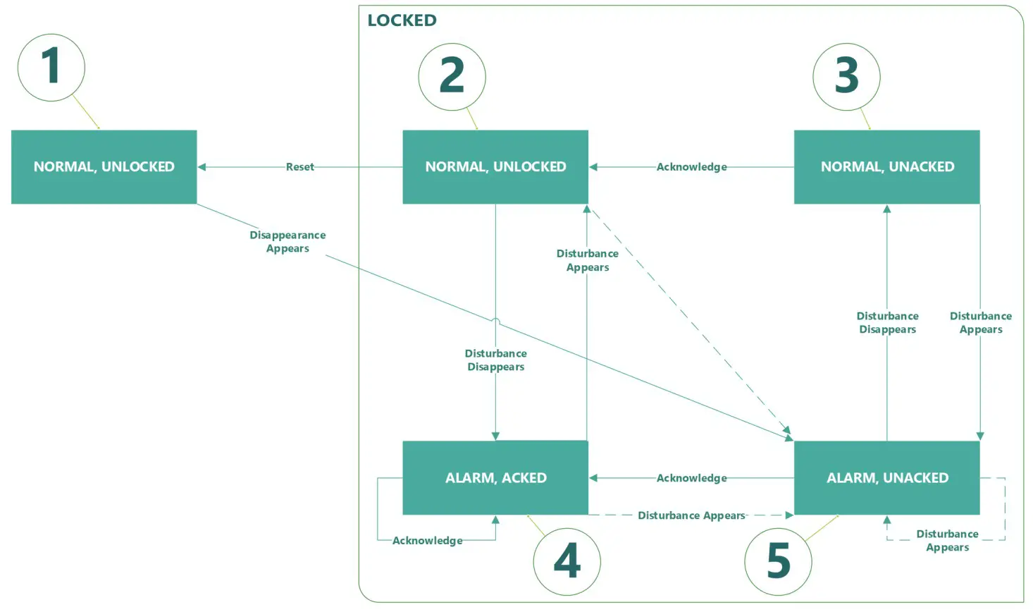
Figure 35 – A-Alarms Application Operation Key
A-ALARMS APPLICATIONS OPERATION KEY
| ALARM | LOCKED | UNACKNOWLEDGED | |
| 1 | 0 | 0 | 0 |
| 2 | 0 | 1 | 0 |
| 3 | 0 | 1 | 1 |
| 4 | 1 | 1 | 0 |
| 5 | 1 | 1 | 1 |
Table 13 – A-Alarms Application Operation Key
B-ALARMS
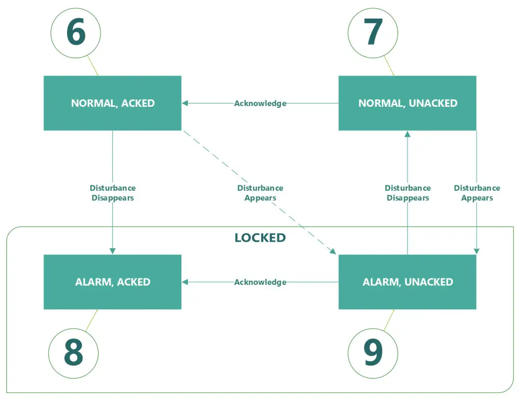 FIGURE 36 – B-Alarms Application Operation Key
B-ALARMS APPLICATIONS OPERATION KEY
| ALARM | LOCKED | UNACKNOWLEDGED | |
| 1 | 0 | 0 | 0 |
| 2 | 0 | 1 | 0 |
| 3 | 0 | 1 | 1 |
| 4 | 1 | 1 | 0 |
| 5 | 1 | 1 | 1 |
Table 14 – B-Alarms Application Operation Key
AVAILABLE PARAMETERS
| ACKNOWLEDGE AND RESET | BACNET OBJECT | R/RW | NOTE |
| A-Alarm acknowledgement | Alamac MVAL,137 | RW | 2: Ready 2: Acknowledge 3: Reset Automatic return to 1 |
| B-Alarm acknowledgement | Balzac MVAL,133 | RW | 1:Ready 2:Acknowledge Automatic return to 1 |
| M A-ALARMS | BACNET OBJECT | R/RW | NOTE |
| A-Alarm state | R | 1:Acknowledged, unlocked 2:Unacknowledged 3:Reset Automatic return to 1 | |
| A-Alarm indication | Aalmlnd MVAL, 236 | R | 1:Normal 2:Alarm |
| A-Alarm code | AalmCode AVAL, 49 | R | 0-9999 |
| B-ALARMS | BACNET OBJECT | R/RW | NOTE |
| B-Alarm state | MVAL, 132 | 1: Acknowledged, unlocked 2: Unacknowledged 3: Reset Automatic return to 1 | |
| B-Alarm indication | Belmond MVAL, 131 | R | 1: Normal 2: Alarm |
| B-Alarm code | BalmCode AVAL, 43 | R | 0…9999 |
| ALARM CLASS SETTINGS | BACNET OBJECT | R/RW 1 | NOTE |
| Alarm configuration for outside air temperature | .AlmCnfTOa MVAL,141 | 2: A-Alarm 2: B-Alarm | |
| Alarm configuration for heat exchanger | AlmCnfHExg MVAL,348 | RW | 1:A-Alarm 2:B-Alarm 3:None |
| Alarm configuration for all fan errors (Feedback fault, error signal or Modbus interrupted) | AlmCnfFanFb MVAI,349 | RW | 1: A-Alarm 2: B-Alarm 3: None (No fan error supervision. — Do not use “None for Modbus fans) |
Table 15 – Available Parameters
Error codes are divided in different groups for easier recognition of the alarm source. Those groups are:
ERROR CODES
| Error code | Error source |
| 1000—1999 | Hardware related errors |
| 2000—2999 | Application related errors |
| 3000—3999 | Communication errors |
| 9000—9999 | rd 3 party related errors |
Table 16 – Error Codes
ERV ALARM CODES CONTINUED
CODE RANGES – HARDWARE
| CODE | ALARM CLASS | NAME/DESCRIPTION | SOURCE | PLANT LOCK | BACNET OBJECT/COMMENT | INFLUENCE OF ALARM |
| 1001 | A | Supply air temperature, Sensor fault | System | Stop | TS.. | :down AHU |
| 1002 | NB | Exhaust air temperature, sensor fault | System | Run | TEh, Active only if sensor available | Shutdown AHU/ No Heat exchanger supervision possible |
| 1003 | B | Extract air temperature, sensor fault | System | Run | TEx, Active only if sensor available Fallback to room temperature control or | supply air control |
| 1004 | NB | Outside air temperature sensor fault | System | Conf. | TOa | Shutdown AHU / fallback to default |
| 1005 | A | Frost protection temperature for heating coil, sensor fault | System | Stop | TFrPrtHcl Active only if HcIHw selected | Shutdown AHU, Frost protection mode |
| 1006 | B | Relative humidity for extract air, sensor fault | System | Run | HuRelEx, Active only if sensor available | Stop Humidity control if all sensors fail |
| 1009 | A | Fire damper position, feedback fault | Process | Stop | FdpFb, Active only if Fdp selected. Plausibility check of fire damper position feedback | Shutdown AHU |
| 1012 | B | Room Temperature, sensor fau ft | System | Run | TR with POS8/QMX3 | Fallback to extract temperature contra. or supply air control |
| 1013 | B | Room air quality, sensor fault | System | Run | AQuaIR with QMX3 or PmR | Stop air quality control if all sensors fail |
| 1014 | B | Extract air quality, sensor fault | System | Run | PmR or AQualR, Particulate matters, Air quality | Stop control if all sensors fail |
| 1017 | B | Room air humidity, sensor fault | System | Run | HuReIR, Active only if sensor available | Stop Humidity control if all sensors fail |
| 1018 | NB | Supply air temp. after preheating coil, sensor fault | System | Run | TSuAfPreHcl , Active only ifsensor available | Shutdown AHU / Shutdown electric preheating coil, fallback value for heat exchanger efficiency |
| 1019 | B | Flow temperature preheating coil, sensor fault | System | Run | TFIPreHcl, Active only if sensor available | Fallback to default value |
| 1020 | B | Air filter, dirty | Process | Run | Operating hour of air filter exceeds limit or delta P, active only if FiIA selected | No reaction |
| 1021 | B | Supply air temperature after heat exchanger, sensor fault | System | Run | TsuAfHExg, Active only if sensor available | Fallback value for Hexg efficiency calculation |
| 1031 | A/B/n | Heat Exchanger fault | Process | Run | RotHExgFlt or HExgCdnMon | Shutdown AHU / Bypass or shutdown HExg / no reaction |
| 1037 | A/Eiln | Supply air fan fault | Process | Conf. | FanSuSpdFb, FanSuFlt Check of fan speed feedback or fault signal | Shutdown AHU / No reaction I No reaction |
| 1038 | A/B/n | Exhaust air fan fault | Process | Conf. | FanSuSpdFb, FanSuFlt Check of fan speed feedback or fault signal | Shutdown AHU / No reaction / No reaction |
| 2001 | A | Emergency off | Process | Stop | EngOff (B1) | AHU off |
| 2002 | A | Smoke detector | Process | Stop | Smext (B1) | Smoke extract mode |
| 2004 | A | Fire Alarm | Process | Stop | Supply (TSu) or extract (TEx) air temperature exceeds max limit | Shutdown extract mode |
| 2005 | B | Supply air temperature, exceeds operating limits | Process | Stop | Supply air temperature (TSu) exceeds min/max limits | No reaction |
| 2012 | A | Preheating coil, over temperature | Process | Stop | PreHclOvrTDet, active only if PreHclEl selected | Shutdown AHU |
| 2013 | A | Outside air damper stops air flow | Process | Stop | Shutdown AHU | |
| 2017 | AIBIn | Heat exchanger efficiency supervision | Process | Conf. | Plausibility check of air temperatures | Shutdown AHU / Bypass or shutdown I no reaction |
Table 17 – Code Ranges – Hardware
CODE RANGES – COMMUNICATION
CODE RANGES – HARDWARE
| CODE | ARM SILS S | ALALANT NAME/DESC RIPTION | SOURCE | POCK | BA CNET OBJECT/COMMENT | INFLUENCE OF ALARM |
| 3005 | B | ,/o extension module, i. _, _ communication fault | System y | Run | POSg active only if device configured | Same reaction as fa. , connection input |
| 3011 | B | Duct pressure sensor, Modbus communication error | System | Run | QBM, Active only if device configured | Fallback to linear Fan speed |
| 3012 | NB | Supply air fan, Modbus communication fault | System | Conf. | Active only if Modbus fan configured | A:Shutdown AHU / B:No reaction Reaction of fan based on fan device configuration |
| 3101 | B | Room sensor, KNX PL-Link communication error | System | Run | Common fault for all PL-Link room devices: PO58.442014440, OMX3.P3o/P4o/P7o Active only if device configured |
Table 18 – Code Ranges – Hardware
MAINTENANCE & SERVICE
PREVENTIVE MAINTENANCE
To achieve maximum performance and service life of equipment, a formal schedule of regular maintenance should be established and adhered to.
If servicing or major repairs are required, the complete unit can be removed as follows:
- Disconnect the electrical power circuit supplying the unit.
- Remove line and low voltage wiring from unit,
- Remove rear access panel.
- Remove supply duct from top of unit.
- Slide unit back out of sleeve.
- Unit may be removed from closet.
To reinstall unit, use the installation procedure outlined above.
![]() WARNING
WARNING
It is illegal to discharge refrigerant into the atmosphere. Use proper reclaiming methods and equipment when installing or servicing this unit. Service should be performed by a QUALIFIED service agency. The refrigerant system contained in the unit normally requires no maintenance since it is a closed, self-contained system.
![]() CAUTION
CAUTION
All appropriate personal protection equipment should be worn when servicing or maintaining this unit.
Personal injury can result from sharp metal edges, moving parts, and hot or cold surfaces.
FAN
The fan should be inspected and cleaned annually in conjunction with maintenance of the motor and bearings. It is important to keep the fan section and motor clean and free from obstruction to prevent imbalance, vibration, and improper operation.
![]() WARNING
WARNING![]() ELECTRIC SHOCK HAZARD
ELECTRIC SHOCK HAZARD
Check motor connections to ensure they are secure and in accordance with the unit wiring diagram.
ECM motors have line voltage power applied at all times. MAKE SURE POWER IS DISCONNECTED BEFORE SERVICING.
FILTER
The air filter and ERV filters should be cleaned or replaced every 30 days or more frequently if severe operating conditions exist. Always replace the filter with the same type and size as originally furnished.
ERV CORE
The Energy Recovery plate heat exchanger (CORE), should be inspected at least twice (2) times a year. The CORE should be removed and cleaned as needed at least once (1) per year. The CORE can be cleaned with light air pressure or with a mild detergent and water solution. Be sure that the CORE is completely dry before reinserting it back into the ERV.
ERV INSULATION
The ERV interior should be inspected with the CORE (2 times a year).
Check and clean the cabinet interior of all dirt and debris. COIL Clean all heat transfer surfaces and remove all dirt, dust, and contaminates that potentially impairs air flow using industry accepted practices. Care should be taken not to bend coil fin material.
CONDENSATE DRAIN PAN AND PIPE
Check and clean all dirt and debris from pan. Ensure drain line is free flowing and unobstructed.
MAINTENANCE UPDATES
Check regularly for a current copy of the maintenance program log which can be found at under “product information”.
UNIT PERFORMANCE
Record performance measurements of volts, amps and water temperature differences (both heating and cooling). A comparison of logged data with start-up and other annual data is useful as an indicator of general equipment condition.
UNIT LOCKOUT
Air or water problem could cause periodic lockouts. The lockout (shutdown) of the units is a normal protective result. Check for dirt in the water system, water flow rates, water temperatures, airflow rates (may be caused by dirty filter) and air temperatures.
LABORATORY TESTING
When the unit has less than 100 operational hours and the coils have not had sufficient time to be “seasoned”, it is necessary to clean the coils with a mild surfactant such as Calgon to remove the oils left by manufacturing processes.
PERFORMANCE TABLES
ERV EFFECTIVENESS TABLE
| SUPPLY TEMPERATURE | RELATIVE HUMIDITY | SUPPLY AIR FLOW | RECOVERY | ||||
| SENSIBLE | LATENT | TOTAL | |||||
| °C | °F | RH % | Ifs | CFM | Effectiveness % | ||
| 25 | 13 | 80 | 47 | 100 | 62.4 | 41.9 | 54.7 |
| 0 | 32 | 80 | 23 | 50 | 70.7 | 53.6 | 65 |
| 0 | 32 | 80 | 37 | 80 | 65.4 | 46 | 59 |
| 0 | 32 | 80 | 56 | 120 | 59.7 | 38.5 | 52.7 |
| -25 | -13 | 80 | 47 | 100 | 65.5 | 41.9 | 56.2 |
Table 19 – ERV Effectiveness
VENTILATION PERFORMANCE
| EXTERNAL STATIC PRESSURE | SUPPLY AIR FLOW | EXHAUST AIR FLOW | |||
| Pa | in. W.C. | L/s | Pa | in. W.C. | L/s |
| 25 | 0.1 | 60 | 123 | 60 | 126 |
| 50 | 0.2 | 56 | 120 | 56 | 120 |
| 75 | 0.3 | 55 | 116 | 55 | 116 |
| 100 | 0.4 | 52 | 109 | 52 | 109 |
| 125 | 0.5 | 49 | 104 | 49 | 104 |
| 150 | 0.6 | 47 | 100 | 47 | 100 |
| 175 | 0.7 | 46 | 97 | 46 | 97 |
| 200 | 0.8 | 41 | 88 | 41 | 88 |
| 225 | 0.9 | 37 | 79 | 37 | 79 |
| 250 | 1 | 34 | 72 | 34 | 72 |
Table 20 – Ventilation Performance
SUPPORT MATERIAL
ASHRAE 62.2 VENTILATION STANDARD TABLES
ASHRAE 62.2 CFM Sizing Chart
| FLOOR AREA | NUMBER OF BEDROOMS / CFM | ||||
| 0-1 | 2-3 | 4-5 | 6-7 | >7 | |
| <1500 | 30 | 45 | 60 | 75 | 90 |
| 1501 — 3000 | 45 | 60 | 75 | 90 | 105 |
| 3001— 4500 | 60 | 75 | 90 | 105 | 120 |
| 4501— 6000 | 75 | 90 | 105 | 120 | 135 |
| 6001— 7500 | 90 | 105 | 120 | 135 | 150 |
| > 7500 | 105 | 120 | 135 | 150 | 165 |
| ANSI/ASHRAE STANDARD 62.2-2010 —Ventilation Air Requirements; values in cfm. The above chart outlines the minimum requirements for continuous ventilation. | |||||
Table 21 – ASHRAE 62.2 CFM Sizing Chart
ROOM COUNT CALCULATION METHOD TABLE
| LIVING SPACE | NUMBER OF ROOMS | X CFM (or L/s) | = | CFM Required |
| Master Bedroom | x 20 cfm (for 10 L/s) | = | ||
| Basement | x 20 cfm (for 10 L/s) | = | ||
| Single Bedroom | x 10 cfm (for 5 L/s) | = | ||
| Living Room | x 10 cfm (for 5 L/s) | = | ||
| Dining Room | x 10 cfm (for 5 L/s) | = | ||
| Family Room | x 10 cfm (for 5 L/s) | = | ||
| Recreation Room | x 10 cfm (for 5 L/s) | = | ||
| Other | x 10 cfm (for 5 L/s) | = | ||
| Kitchen | x 10 cfm (for 5 L/s) | = | ||
| Bathroom | x 10 cfm (for 5 L/s) | = | ||
| Laundry Room | x 10 cfm (for 5 L/s) | = | ||
| Utility Room | x 10 cfm (for 5 L/s) | = | ||
| TOTAL VENTILATION REQUIREMENT | = | |||
Table 22 – Room Count Calculation Method Table
STARTUP & PERFORMANCE CHECKLIST
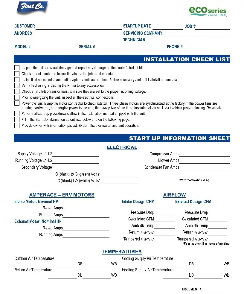
FIGURE 37 – Startup & Performance Checklist (1 of 2)
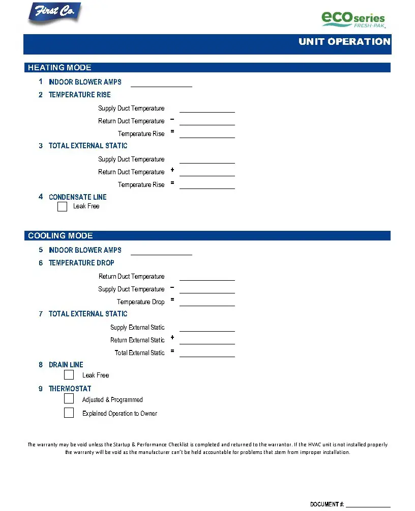
FIGURE 38 – Startup & Performance Checklist (2 of 2)
Manufactured by:![]()
8273 Moberly Lane Dallas, TX 75227
www.firstco.com
The manufacturer works to continually improve its products and as a result, it reserves the right to change design and specifications without notice.
©2021 First Co., 8273 Moberly Lane, Dallas, TX 75227


