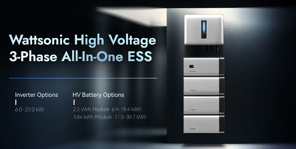
WATTSONIC 4to20kw 3P Series High Voltage ESS

Product Information: Wattsonic 4~20kw-3P Series
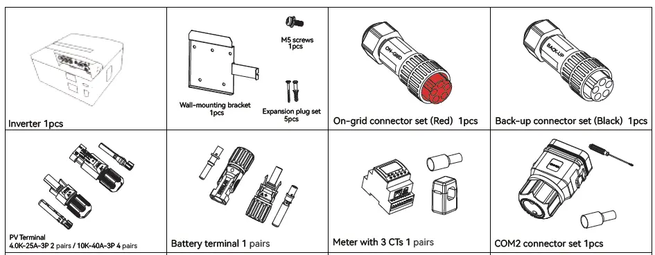
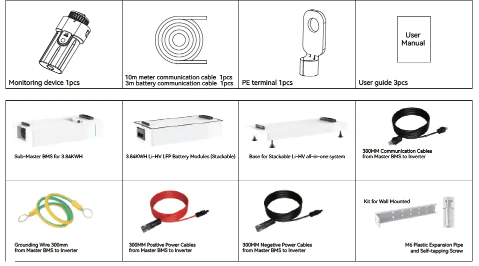
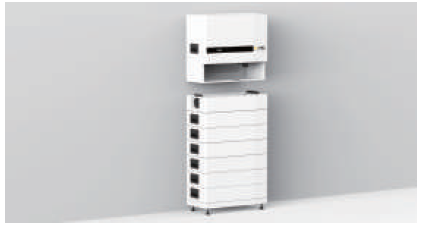
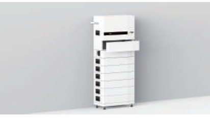
The Wattsonic 4~20kw-3P Series is an all-in-one system that comes with an inverter, wall-mounting bracket, expansion plug set, on-grid connector set, back-up connector set, PV terminal, battery terminal, meter with 3 CTs, monitoring device, communication cables, user manual, sub-master BMS for 3.84KWH, grounding wire, and stackable Li-HV LFP battery modules.
Part 1: Installation
Before installation, check the packing list. Install the base and kit for wall mounted as per the electrical wiring diagram. Ensure that the installation location and space and angle requirements are met.
Part 2: Electrical Connection
Install the battery module and sub-master BMS. Connect the AC cable, PV cable, and battery power cable as per the cable requirements. Install the inverter and connect it to the monitoring device using the communication cables provided. Connect the meter and CTs as per the meter terminals definition. Finally, connect the communication cables to the multifunction relay and terminate the CAN and RS485 communication lines.
Cable Requirements:
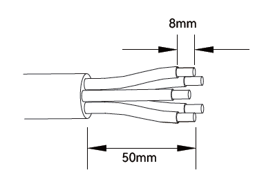
- AC Cable: Outside diameter – 13.0-18.0 mm, Conductor core section – 5.0-8.0 mm
- PV Cable: Outside diameter – 5.9-8.8 mm
- Battery Power Cable: Outside diameter – 5.0-8.0 mm
Meter Terminals Definition:
| No. | Definition | Function |
|---|---|---|
| 1-6 | L1-S1, L1-S2, L2-S1, L2-S2, L3-S1, L3-S2 | To detect the CT current |
| 7-10 | L1, L2, L3, N | Connect to grid to detect power grid voltage |
| 12 | L | Power supplied from grid |
| 13 | RS485 | Communicate with inverter |
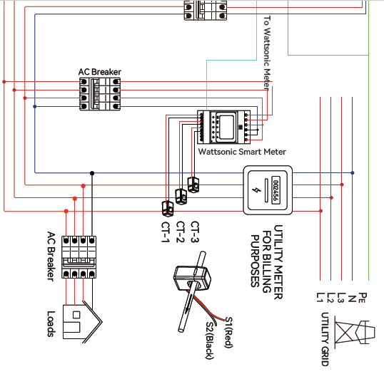
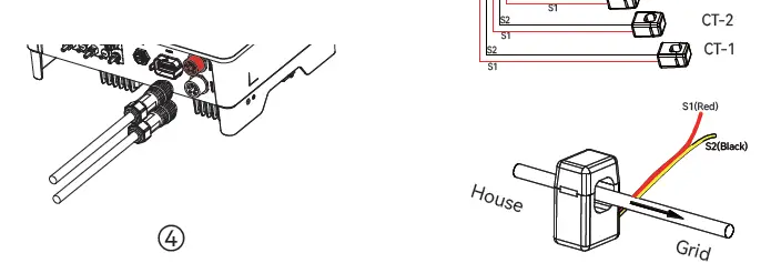
Note: The direction of the arrow inside the CT should be consistent with the direction of the arrow outside the CT.
Installation
Check Packing List
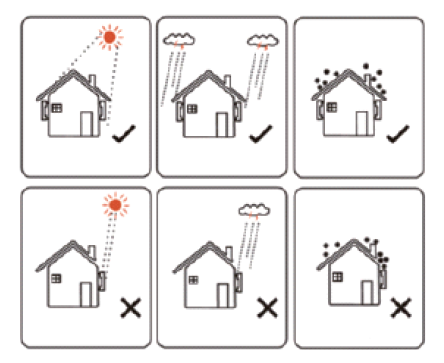
Installation Location
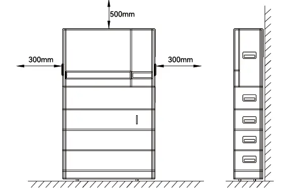
Installation Space and Angle
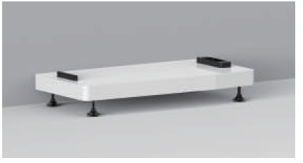
Install the base
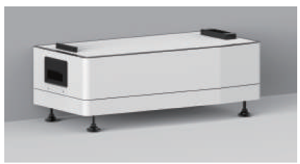
Install the battery module & Sub-Master BMS
Install the inverter
Install the kit for wall mounted & cables cover
Electrical Connection
Check Packing List
| Cable types AC cable | Cable requirements | |
| Outside diameter 13.0-18.0 mm | Conductor core section 2.5-10.0 mm² | |
| PV cable | 5.9-8.8 mm | 2.5-4.0 mm² |
| Battery power cable | 5.0-8.0 mm | 10 mm² |
- AC cable: On-grid side uses a five-core cable (L1, L2, L3, N, and PE). Back-up side uses a four-core cable (L1, L2, L3, N).
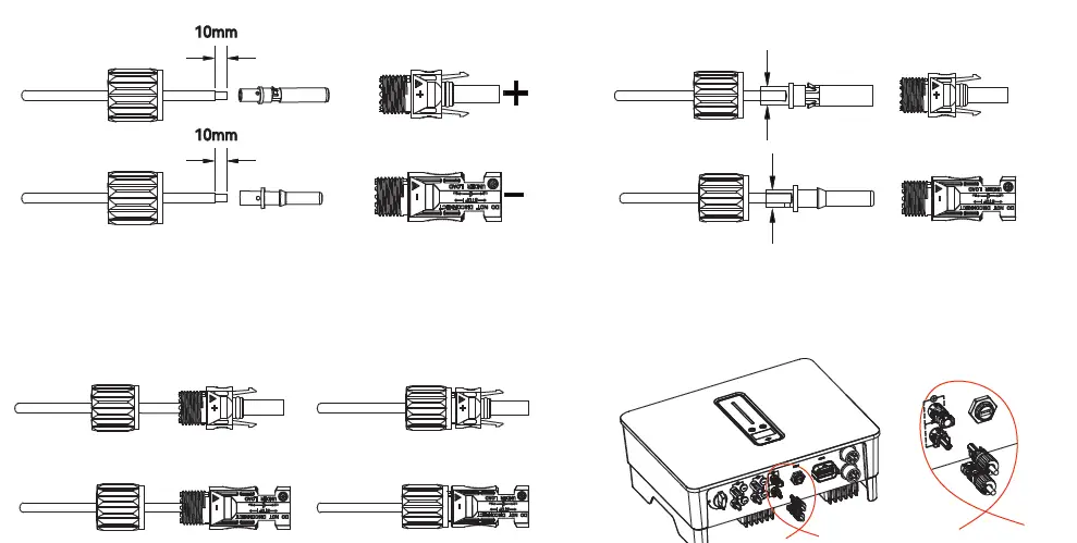
- AC Connector: Please distinguish the on-grid and back-up connector, On-grid connector is red and Back-up connector is Black.
- Battery power cable: If the conductor core of the battery cable is too small, which may cause poor contact between the terminal and the cable, please use the cable specified in the above table, or contact Wattsonic to purchase terminals of other specifications.
Electrical wiring diagram
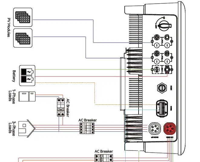
AC Connection
Monitoring Device Installation
Meter and CT connection
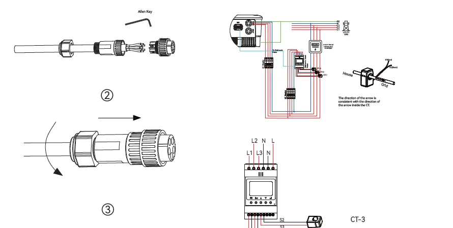
Meter terminals definition
| No. | Definition | Function |
| 1 | L1-S1 | To detect the CT current |
| 2 | L1-S2 | |
| 3 | L2-S1 | |
| 4 | L2-S2 | |
| 5 | L3-S1 | |
| 6 | L3-S2 | |
| 7 | L1 | L1/L2/L3/N connect to grid to detect power grid voltage |
| 8 | L2 | |
| 9 | L3 | |
| 10 | N | |
| 12 | L | Power supplied from grid |
| 13 | N | |
| RS485 | RS485 | Communicate with inverter |
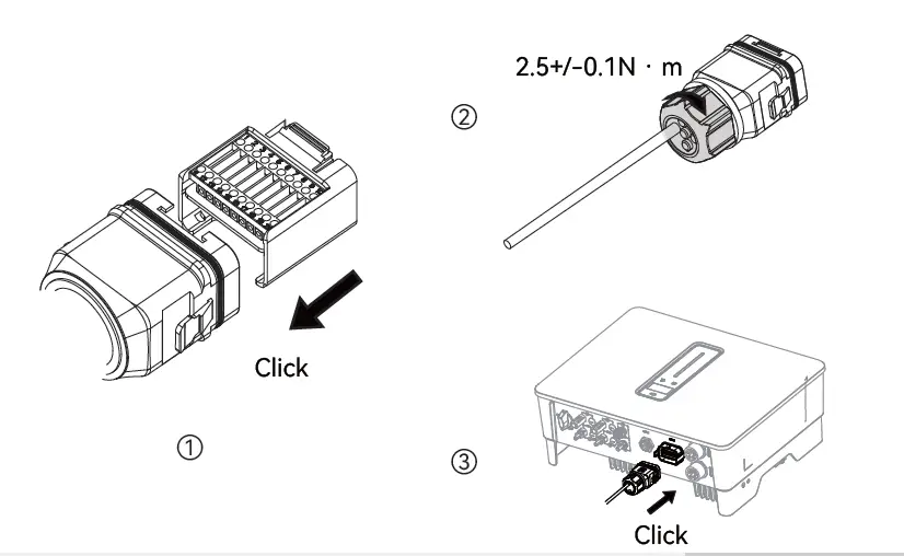
Communication Connection
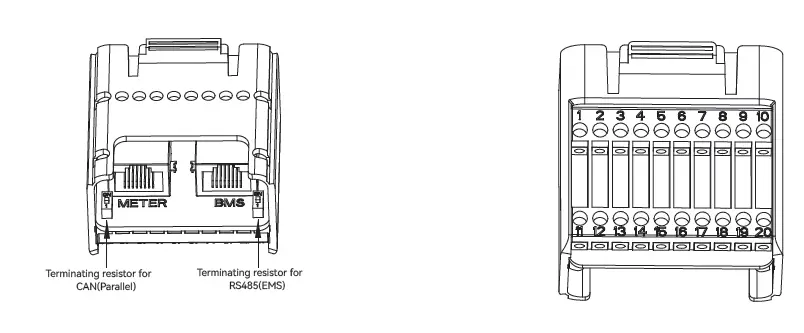
| Pin | Definition | Function |
| RJ45-1 | RS 485 | Communicate with Meter |
| RJ45-2 | CAN | Communicate with BMS |
| 1 | COM | Multifunction Relay |
| 2 | NO (Normally Open) | |
| 3-4 | / | Reserved |
| 5 | DRM4/8 | DRED For Australia and New Zealand |
| 6 | DRM3/7 | |
| 7 | DRM2/6 | |
| 8 | DRM1/5 | |
| 15 | COM D/0 | |
| 16 | REF D/0 | |
| 9-10 | / | Reserved |
| 11 | Fast stop + | Fast stop |
| 12 | Fast stop – | |
| 13 | 485 B1 | EMS |
| 14 | 485 A1 | |
| 17 | CANL_P | CAN for parallel connection of inverters |
| 18 | CANH_P | |
| 19-20 | / | Reserved |
Connect the Meter and BMS communication cables
Connect other cables
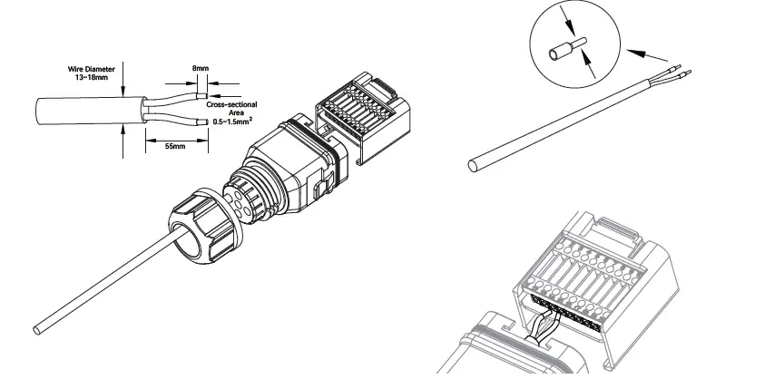
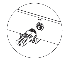
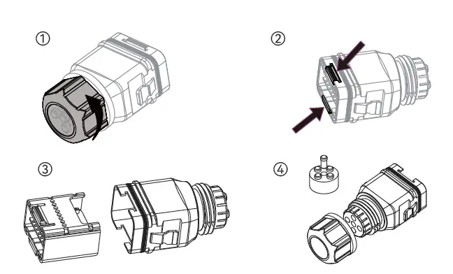
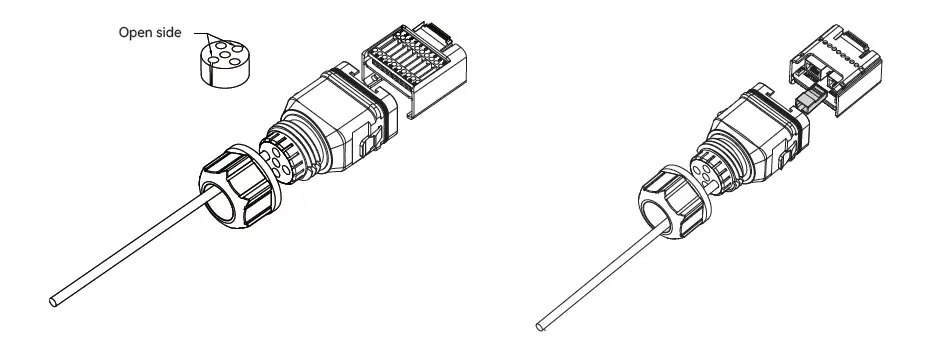
Installing the COM Connector
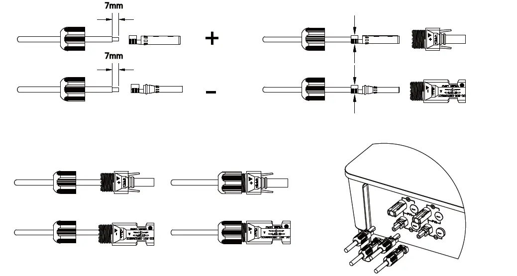
PV string connection
Power cable of the battery connection