AUSTRALIAN MONITOR ES2120P Power Amplifier

IMPORTANT SAFETY INFORMATION
- Read these instructions.
- Keep these instructions.
- Heed all warnings.
- Follow all instructions.
- Do not use this apparatus near water.
- Clean only with dry cloth.
- Do not block any ventilation openings. Install in accordance with the manufacturer’s instructions.
- Do not install near any heat sources such as radiators, heat registers, stoves, or other apparatus (including amplifiers) that produce heat.
- Do not defeat the safety purpose of the polarized or grounding-type plug. A polarized plug has two blades with one wider than the other. A grounding type plug has two blades and a third grounding prong. The wide blade or the third prong are provided for your safety. If the provided plug does not fit into your outlet, consult an electrician for replacement of the obsolete outlet.
- Protect the power cord from being walked on or pinched particularly at plugs, convenience receptacles, and the point where they exit from the apparatus.
- Only use attachments/accessories specified by the manufacturer.
- Use only with the cart, stand, tripod, bracket, or table specified by the manufacturer, or sold with the apparatus. When a cart is used, use caution when moving the cart/apparatus combination to avoid injury from tip-over.
- Unplug this apparatus during lightning storms or when unused for long periods of time.
- Refer all servicing to qualified service personnel. Servicing is required when the apparatus has been damaged in any way, such as power supply cord or plug is damaged, liquid has been spilled or objects have fallen into the apparatus, the apparatus has been exposed to rain or moisture, does not operate normally, or has been dropped.
- This appliance shall not be exposed to dripping or splashing water and that no object filled with liquid such as vases shall be placed on the apparatus.
- Plug this apparatus to the proper wall outlet and make the plug to be disconnected readily operable.
- Mainsplug is used as disconnected device and it should remain readily operable during intended use. In order to disconnect the apparatus from the mains completely, the mains plug should be disconnected from the mains socket outlet completely.
- WARNING: To reduce the risk of fire or electric shock, do not expose this apparatus to rain or moisture.
- An appliance with a protective earth terminal should be connected to a mains outlet with a protective earth connection.
- The apparatus should be disconnected from the mains completely before speaker wiring. The speaker output should be proper protected from direct contact and pay attention to speaker connections, terminals and speaker wiring during normal operation.
ESP SERIES
Congratulations on choosing Australian Monitor for your professional amplification requirements.
The ES2120P is a 2RU 2 channel 120W amplifier. This amplifier features 100V line and 4Ω output.
The Australian Monitor ESP series gives the contractor a low cost solution in applications that are price sensitive but still require a high quality of sound reproduction and reliability.
WARNING
TO PREVENT FIRE OR SHOCK HAZARD, DO NOT USE THE PLUG WITH AN EXTENSION CORD, RECEPTACLE OR OTHER OUTLET UNLESS THE BLADES CAN BE FULLY INSERTED TO PREVENT BLADE EXPOSURE.
TO REDUCE THE RISK OF FIRE OR ELECTRIC SHOCK, DO NOT EXPOSE THIS APPLIANCE TO RAIN OR MOISTURE.
TO PREVENT ELECTRICAL SHOCK, MATCH WIDE BLADE PLUG TO WIDE SLOT AND FULLY INSERT.
CAUTION
THESE SERVICING INSTRUCTIONS ARE FOR USE BY QUALIFIED SERVICE PERSONNEL ONLY.
TO REDUCE THE RISK OF ELECTRIC SHOCK DO NOT PERFORM ANY SERVICING OTHER THAN THAT CONTAINED IN THE OPERATING INSTRUCTIONS UNLESS YOU ARE QUALIFIED TO DO SO.
 The lightning flash with arrowhead symbol, within an equilateral triangle, is intended to alert the user to the presence of uninsulated “dangerous voltage” within the product’s enclosure that may be of sufficient magnitude to constitute a risk of electric shock to persons.
 WARNING
TO REDUCE THE RISK OF ELECTRIC SHOCK, DO NOT REMOVE COVER (OR BACK). NO USER SERVICEABLE PARTS INSIDE. REFER SERVICING TO QUALIFIED SERVICE PERSONNEL.
 The exclamation point within an equilateral triangle is intended to alert the user to the presence of important operating and maintenance (servicing) instructions in the literature accompanying the appliance
 For European Union countries: This symbol on the product or its packaging indicates that this product must not be disposed of with other waste. Instead, it is your responsibility to dispose of your waste equipment by handing it over to a designated collection point for the recycling of waste electrical and electronic equipment.
Please contact your local authority for further details of your nearest designated collection point.
FEATURES & PROTECTION FEATURES
FEATURES
• ES2120P – 2 x 120W
• 100V and 4Ω outputs
• XLR Through Output
• Level Adjustment
• 2 RU
PROTECTION FEATURES
• Short-circuit protection
• Over load protection
• Thermal protection
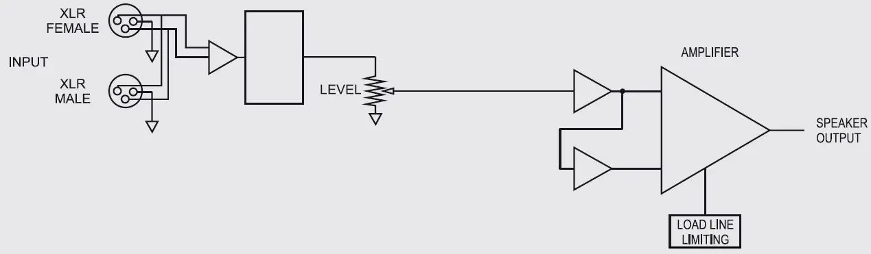
ES2120P AMPLIFIER BLOCK DIAGRAM
FRONT PANEL
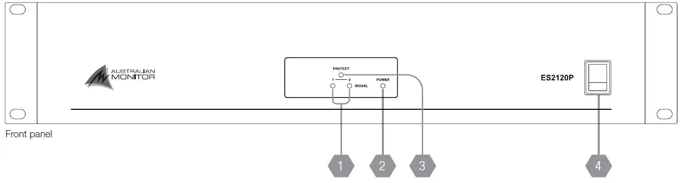
- SIGNAL
This LED indicates the unit is outputting a signal. - POWER
This LED indicates the unit is on. - PROTECTION
This LED indicates that the amplifier is protection due to a short circuit or overload condition at the output terminals. - POWER SWITCH
This switches the power to the unit on and off. The up position is on.
REAR PANEL
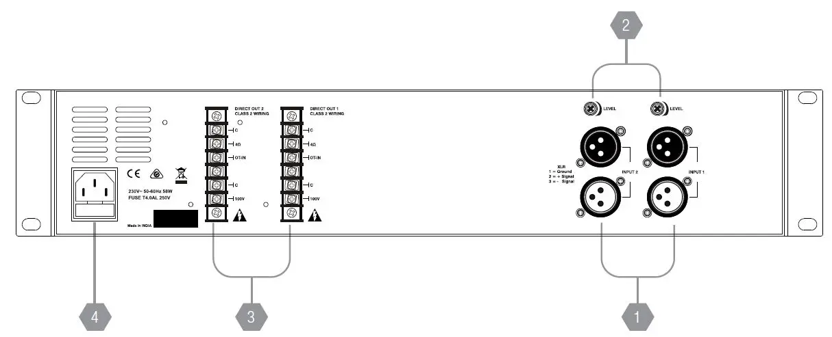
- INPUT
These 3 pin XLR sockets accept the source input for each channel. One input is a male XLR, the other is a female XLR. The male XLR is normally used as a thru output. When wiring from unbalanced sources, pins 1 and 3 should be shorted together. The input sensitivity (voltage required to drive amplifier to maximum power) of the amplifier is 150mV with the Input Level Control set at maximum. - LEVEL
This potentiometer controls the level of the signal through the amplifier channel. Minimum position is Off and maximum gives a sensitivity of 150mV. The input level control should be run above the 12 o’clock position (half way) to avoid clipping the input stage. - SPEAKER OUTPUT
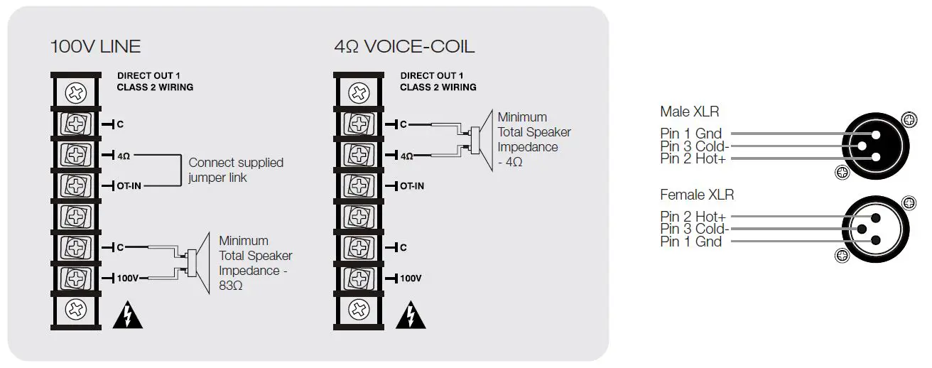
Speaker connections are provided on screw terminals. 4Ω low impedance and 100V.
IMPORTANT: If you are using the 100V output you must connect the jumper link between 4Ω and OT-INMINIMUM IMPEDANCE ES2120P DISTRIBUTED LINE OUTPUT 100V 83Ω LOW IMPEDANCE OUTPUT 4Ω - IEC MAINS INPUT SOCKET
This is a standard IEC 60320-C14 socket. It accepts a standard IEC mains cable, provided. The fuse drawer contains the mains fuse and a spare. Consult the specification section for fuse ratings.
- Always replace the fuse with one of the same value and type.
- Always disconnect power to the amplifier before replacing fuses.
INSTALLATION
POWER REQUIREMENTS
Power consumption for your model of the ESP Series amplifier is indicated on the rear panel for 1/8th output power.
Ensure that your mains voltage is the same as the rear panel mains voltage marker (±10%).
MOUNTING
The ESP Series amplifiers are two rack units high (2U) and will fit a standard EIA 19” or rack.
Typically amplifiers may be stacked directly on top of each other with no need for spacing between units, unless installed in high ambient temperature environments where a single rack unit space between amplifiers will assist cooling further.
COOLING
The power amplifiers are cooled by axial fans which draw air inside the amplifier and expel the heated air outside the amplifier.
An unrestricted airflow into and out from the amplifier must be provided. Any restriction of the air flow will cause heat to build up within the unit and possibly force the unit into its thermal shutdown mode.
If the amplifiers are to be operated in an environment where the airflow is restricted such as sealed racks, cooling should be supplemented by extra cooling fans to evacuate the heated air and aid the flow of cool air through the unit.
OUTPUT WIRING
When wiring to your speakers always use the largest gauge wire your connector will accept. The longer the speaker lead the greater the losses which will result in reduced power and less damping at the load. We recommend using a heavy duty, two core flex (four core flex if bi-amping) 10 to 12 gauge (2mm2 to 2.5mm2 or 50/0.25 or equivalent) as a minimum.
SPEAKER OUTPUT
The output terminal strip accepts wire sizes from 16-22AWG (1.5mm2 – 0.35mm2) or spade lugs. The following table should be used as a guideline for cable sizes. Regulations in your area may require different gauged wire and should be checked before using.
| OUTPUT | DISTANCE | |
| 100V | Upto 50m | AWG24(0.2mm2) |
| 50m – 200m | AWG18(0.75mm2) | |
| Over 200m | AWG16(1.5mm2) | |
| 4Ω | Upto 10m | AWG18(0.75mm2) |
| 10m – 30m | AWG13(2.5mm2) | |
| Over 30m | Not Recommended |
NOTE: Only connect one output – either 100V or 4Ω
INPUT CONNECTIONS
When wiring balanced inputs, wire the male plug so that it mates with the female XLR on the back of the amplifier. Follow the pin outs listed in the diagram below.
When wiring as a unbalanced input, wire the male plug so that it mates with the female XLR on the back of the amplifier.
Connect Cold- to Gnd as there is no cold signal available in an unbalanced connection.
TROUBLESHOOTING
| TROUBLE | LIKELY CAUSE | REMEDY |
| Power LED not on | Power not reaching amplifier | Check power switch is on Check mains connection Check mains fuse |
| Distorted sound | Output is short circuit Input is overloaded Output is being over driven | Check speaker loads for shorts Reduce input level at source Reduce volume levels on rear panel |
| No sound but amplifier is on | Volume controls down Amplifier has overheated | Check volume controls Check for obstructions above and below Make sure the amplifier is well ventilated |
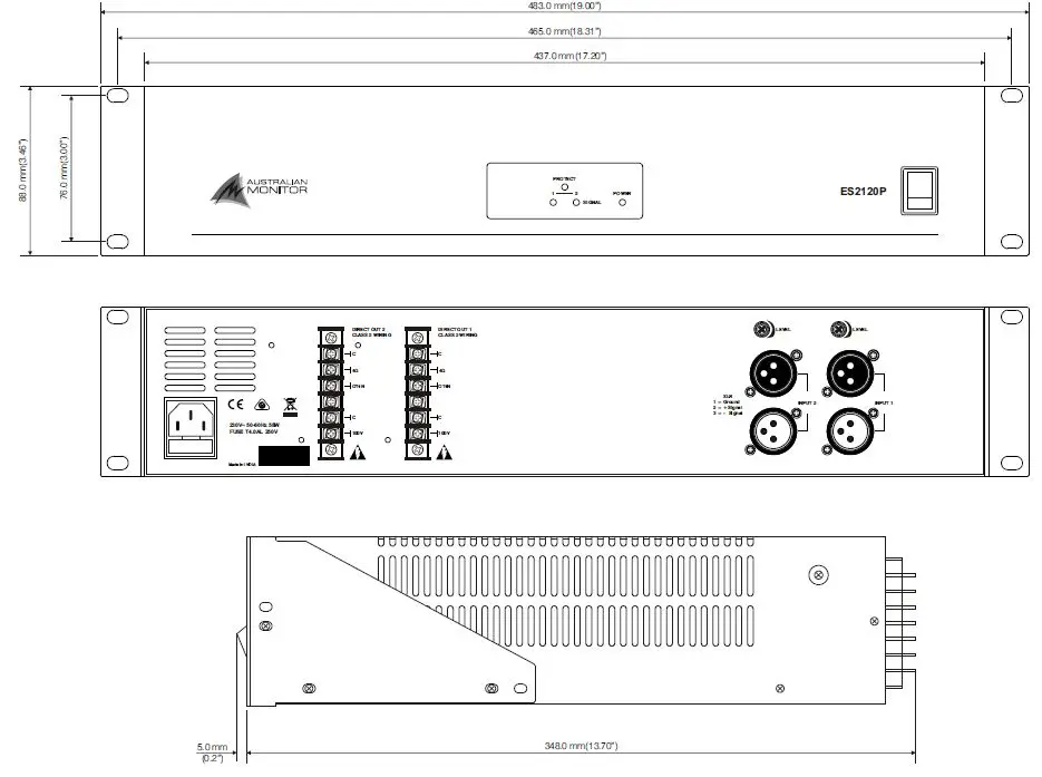
DIMENSIONS
SPECIFICATIONS
| Model | OUTPUT 1 | OUTPUT 2 | Conditions/Comments |
| AUDIO OUTPUT | |||
| 4Ω (SINGLE CHANNEL DRIVEN) 4Ω (BOTH CHANNEL DRIVEN) 100V (SINGLE CHANNEL DRIVEN) 100V (BOTH CHANNEL DRIVEN) | 133W/158mV 130W/156mV 126W/157mV 125W/158mV | 131W/160mV 128W/158mV 123W/159mV 121W/158mV | 1kHz. 1%THD. -5W/+5W |
| MAX OUTPUT LEVEL (DBV/ VRMS) | 22.6V | 22.6V | 4Ω Output. 150mV |
| SYSTEM GAIN | 44dB | 44dB | 4Ω, 150mV |
| FREQUENCY RESPONSE 4Ω FREQUENCY RESPONSE 100V | 14Hz ~ 34kHz 90Hz ~ 30kHz | 15Hz ~ 34kHz 90Hz ~ 30kHz | 3dB below clipping, +0/-3dB.±5Hz 3dB below clipping, +0/-3dB.±5Hz Low Frequency ±2kHz High Frequency |
| SIGNAL TO NOISE RATIO 4Ω SIGNAL TO NOISE RATIO 100V | 91dB/150mV 91dB/150mV | 90dB/150mV 90dB/150mV | Pot Wound Max, Max Output, 1kHz, A-Weighted |
| THD+N. 4Ω. 1kHz THD+N. 4Ω. FREQ. BAND
THD+N. 100V. 1kHz THD+N. 100V. FREQ BAND | 0.01% 0.14%
0.03% 0.05% | 0.01% 0.14%
0.04% 0.05% | 3dB below clipping, 1kHz. A-Weighted 3dB below clipping, Freq Band. 20kHz BW, A-Weighted 3dB below clipping, 1kHz. A-Weighted 3dB below clipping, Freq Band. 20kHz BW, A-Weighted |
| AUDIO SENSITIVITY | |||
| AUDIO INPUT SENSITIVITY | 150mV | 150mV | Rated Power, 100V Output |
| NO LOAD VOLT.4Ω | 22.5V | 4Ω | |
| LOADED VOLT 4Ω | 22.1V | 4Ω | |
| LED SIGNAL | -34dBr | ||
| AUDIO MISCELLANEOUS | |||
| INPUT IMPEDANCE | 20kΩ | ||
| INPUT CMRR | > 57dBr | ||
| Model | OUTPUT 1 | OUTPUT 2 | Conditions/Comments |
| POWER REQUIREMENTS | |||
| AC INPUT | 230Vac, 50-60Hz | ±10% | |
| AC POWER FACTOR | > 0.55 | ||
| AC INPUT CONNECTOR | IEC 60320-C14 | ||
| AC MAINS FUSE | 4A SB glass | ||
| MAXIMUM INRUSH CURRENT | 60A | ||
| RMS CURRENT DRAW IDLE 1/8TH POWER 1/3RD POWER FULL POWER | 0.1A 0.4A 1.0A 2.3A |
230V AC, 50Hz, 100V Output, 1kHz, Sine | |
| POWER CONSUMPTION IDLE 1/8TH POWER 1/3RD POWER FULL POWER | 11W 58W 124W 334W |
230V AC, 50Hz, 100V Output, 1kHz, Sine | |
| EFFICIENCY 1/8TH POWER 1/3RD POWER FULL POWER | 67% 71% 74% | 230V AC, 50Hz, 100V Output, 1kHz, Sine | |
| THERMAL DISSIPATION IDLE 1/8TH POWER 1/3RD POWER FULL POWER | 38 188 413 1110 |
Excludes Load Power (1W = 3.412BTU/Hr) | |
| MISCELLANEOUS | |||
| PRODUCT DIMENSIONS (WITH RACK EARS) PRODUCT DIMENSIONS (WITHOUT RACK EARS) | 483mm x 353mm x 88mm (19.02″ W x 13.9″ D x 3.46″ H) 437mm x 353mm x 88mm (17.20″ W x 13.9″ D x 3.46″ H) | ||
| SHIPPING DIMENSIONS | 556mm x 471mm x 171mm (21.9″ W x 18.5″ D x 6.7″ H) | ||
| NET WEIGHT | 7.45 Kg (16.43 lb) | ||
| SHIPPING WEIGHT | 8.8 Kg (19.40 lb) | ||
| MOUNTING | 2RU | ||
| OPERATING TEMPERATURE | 0°C to 40°C (95% RH) | ||
| FINISH | Powder Coated Steel | ||
| COLOUR | Black (Satin) | ||
| ACCESSORIES | IEC Mains cable, Rubber Feet x 4 | ||
| APPROVALS | CE, IEC, RCM | ||
ENGINEERED BY AUSTRALIAN MONITOR
Address: Unit 1, 2 Daydream Street, Warriewood NSW 2102 Australia
Website: www.australianmonitor.com.au
International enquiries email: [email protected]
ABN 86 003 231 187


 Amplifier Installation Guide")


