![]()
User
Manual
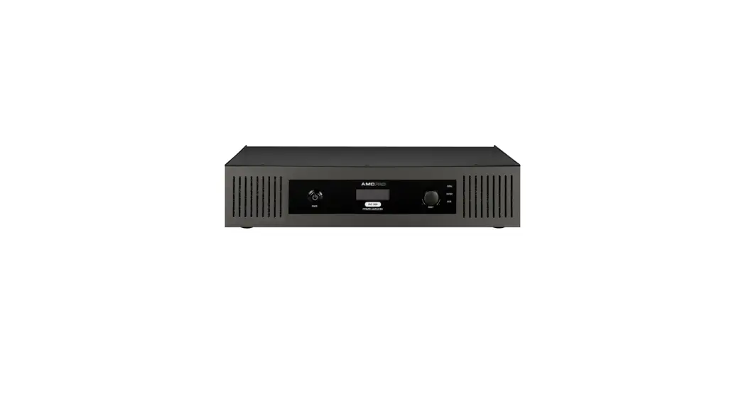
iAC Installation Power Amplifier
Safety instructions
When using this electronic device, basic precautions should always be taken, including the following:
- Read all instructions before using the product.
- Do not use this product near water (e.g., near a bathtub, washbowl, kitchen sink, in a wet basement or near a swimming pool etc). Care should be taken that objects do not
fall into liquids and liquids would not be spilled on the device. - Use this device when you are sure that it has a stable base and it is fixed securely.
- This product, in combination with loudspeakers, may be capable of producing sound levels that could cause permanent hearing loss. Do not operate for a long period of
time at a high volume level or at a level that is uncomfortable. If you experience any hearing loss or ringing in the ears, you should consult with an otorhinolaryngologist. - The product should be located away from heat sources such as radiators, heat vents, or other devices that produce heat.
- Note for power connections: for pluggable equipment, the socket-outlet shall be installed near the equipment and shall be easily accessible.
- The power supply should be undamaged and never share an outlet or extension cord with other devices. Never leave the device plugged into the outlet when it is not
being used for a long period of time. - Power disconnection: when the power cord connected to the power grid is connected to the machine, the standby power is turned ON. When the power switch is turned ON, the main power is turned ON. The only operation to disconnect the power supply from the grid, unplug the power cord.
- Protective Grounding – An apparatus with class I construction shall be connected to a power outlet socket with a protective grounding connection. Protective Earthing – An apparatus with class I construction shall be connected to a main socket outlet with a protective earthing connection.
- The lightning flash with an arrowhead symbol, with an equilateral triangle, is intended to alert the user to the presence of uninsulated dangerous voltage within the product’s enclosure that may be of sufficient magnitude to constitute a risk of electric shock to persons.

- The exclamation mark within an equilateral triangle is intended to alert the user to the presence of important operating and maintenance (servicing) instructions in the literature accompanying the appliance.

- There are some areas with a high voltage inside, to reduce the risk of electric shock do not remove the cover of the device or power supply.
The cover should be removed by qualified personnel only. - The product should be serviced by qualified service personnel if:
– The power supply or the plug has been damaged.
– Objects have fallen into or liquid has been spilled on the product.
– The product has been exposed to rain.
– The product has been dropped or the enclosure damaged.
RISK OF ELECTRIC SHOCK DO NOT OPEN | To reduce the risk of electric shock, do not remove screws. No user-serviceable parts inside. Refer servicing to qualified service personnel. To reduce the risk of fire, electric shock or product damage, do not expose this apparatus to rain, moisture, dripping, or splashing and no objects filled with liquids, such as vases, shall be placed on the apparatus. |
Before you start
AC amplifiers with an integrated signal processor are designed for 100 V and low impedance background music systems. The model line consists of single-channel and two-channel amplifiers.
They all have a RS 232 control port for integration amplifier with third-party automation systems. Balanced Phoenix and stereo RCA input with audio link connection for easy installation, multiple voltage output suitable for 4 Ω, 70 V, and 100 V speaker lines.
FEATURES
- Muting function
- Integrated signal processors
- Locking function
- RS232 control port
- Stand-by mode
- for 100V and low impedance music systems
- Supports 4 Ω, 70 V and 100 V speaker installations
- Ability to control treble, middle, and bass tones
- Stereo RCA AUX input
Operation
Front Panel | iAC 10
- Power button
- LCD display
- Rotary encoder
- Signal, limiter & mute indicators
Rear Panel | iAC 120

- Stereo RCA & balanced Phoenix inputs
- Link output
- RS232 serial interface
- Reset button
- Main output
- Main power connector
Front Panel | iAC 240, iAC 360
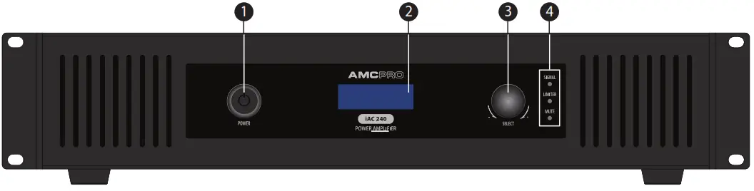
- Power button
- LCD display
- Rotary encoder
- Signal, limiter & mute indicators
Rear Panel | iAC 240, iAC 360
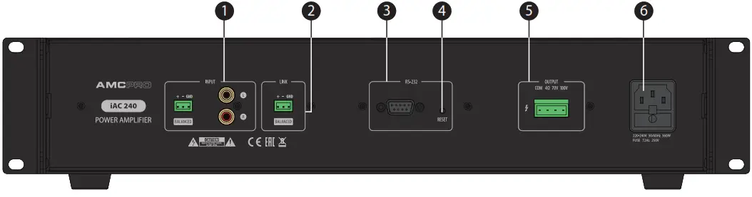
- Stereo RCA & balanced Phoenix inputs
- Link output
- RS232 serial interface
- Reset button
- Main output
- Main power connector
Front Panel | iAC 2X240
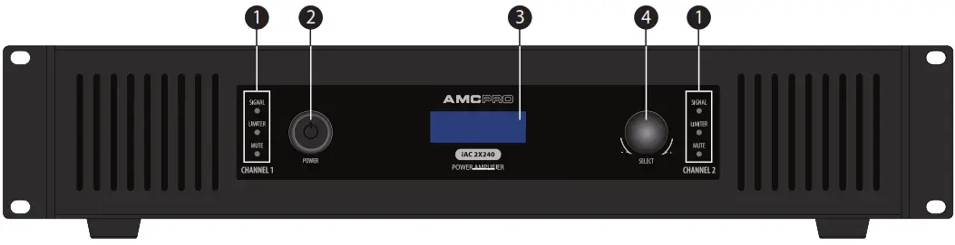
- Signal, limiter & mute indicators
- Power button
- LCD display
- Rotary encoder
Rear Panel | iAC 2X240
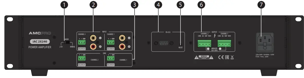
- Mode switch
- Stereo RCA & balanced Phoenix inputs
- Link outputs
- RS232 serial interface
- Reset button
- Main output
- Main power connector
Front panel functions
LED INDICATORS
THE SIGNAL INDICATOR illuminates when indicates an audio signal in the amplifier’s input.
LIMITER INDICATOR – the amplifier has a built-in audio signal limiter in order to limit output power. In case if input audio signal exceeds the maximum amplitude needful to achieve maximum power, the audio limiter reduces the audio signal level to a safe value and indicates activity using LIMIT LED.
MUTE INDICATOR illuminated when mute function is activated. The red LED indicates muted channel.
POWER BUTTON
Switch amplifier power ON or OFF.
LCD DISPLAY
LCD screen displays main information about amplifiers: volume level, tone controls levels, muting, locking, stand-by status or sync settings.
ROTARY ENCODER
Designated to adjust amplifier parameters. Rotate the encoder to adjust parameters and push it to enter the menu or sub-menu. Press and hold for a second to return the default screen. Push rotary encoder shortly to select CH1 or CH2, hold it to activate the selected channel menu. In order to disable LOCK mode press and hold the encoder for 5 seconds. Turn or press the knob to get the back device from standby mode.
Rear panel functions
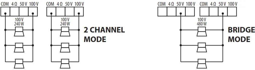
MODE SWITCH (iAC 2X240)
The amplifier can be set to operate in 2 modes: 2 controllable channels or single-channel mode. Both selections can operate in a 100 V line.
STEREO RCA & BALANCED PHOENIX INPUTS
RCA input for line-level audio.
AMPLIFIER OUTPUTS
Audio outputs for 4 Ω, 70 V, and 100 V speaker lines. Only one output can be used at a time. Operating amplifiers with more than one output may cause damage the amplifier or connected speakers.
RS232 SERIAL INTERFACE
Designed to control the main function of is amplifiers by using the serial interface.
RS232 protocol is listed on page 8.
RESET BUTTON
This button resets all amplifier parameters to default values. To activate this function, press and hold the button for two seconds.
MAIN POWER CONNECTOR
Power connector for mains power.
One Knob To Control Everything
iAC series features a graphic LCD display and a single rotary/push encoder allowing easy control of all device parameters. Menu system
In normal operating mode, LCD shows the volume of each channel. Push the rotary encoder to enter the other channel or back to the previous model.
Push and hold the rotary encoder to enter the main menu and access more controls of parameters.
3 band EQ EQ
adjustments can be made for each channel individually. Muting
Each channel can be individually muted. Sync Settings
The function allows linking both channels and copying settings from one channel to another in order to control both amplifier channels at once. Lock This function locks front panel control in order to prevent unauthorized access to the amplifier control menu or volume adjusting. To disable the function press and hold the rotary encoder for 5 seconds. Lock
Lock
function affects front panel control only, serial control and reset functions are not free of locking. Lock mode can be also enabled or disabled by using the RS232 command.  Active standby mode
Mutes amplifier and turns off LCD display in order to save power. This mode is indicated by the red color LED inside the power button. In order to disable standby mode turn or push the rotary encoder. The standby mode also can be enabled or disabled by using the RS232 command.
COM Port Settings
Baud Rate: 9600
Parity: None
Data Bits: 8
Stop Bits: 1
Flow Control: No
| RS232 codes | Send Sequences | For iAC 2X240 model | Bass – Ch2 |
| RS232 codes are listed in HEX | Vol + Ch1 | 69 41 43 55 02 05 01 02 AA |
| For iAC 120/240/360 models | 69 41 43 55 01 02 01 01 AA | Mute Ch2 |
| Vol + | Vol – Ch1 | 69 41 43 55 02 02 01 A1 AA |
| 69 41 43 55 01 02 01 01 AA | 69 41 43 55 01 02 01 02 AA | Unmute Ch2 |
| Vol – | Mute Ch1 | 69 41 43 55 02 02 01 A0 AA |
| 69 41 43 55 01 02 01 02 AA | 69 41 43 55 01 02 01 A1 AA | Sync/Copy Ch1 To Ch2 |
| Mute | Unmute Ch1 | 69 41 43 55 01 01 01 01 AA |
| 69 41 43 55 01 02 01 A1 AA | 69 41 43 55 01 02 01 A0 AA | Sync/Copy Ch2 To Ch1 |
| Unmute | Treble + Ch1 | 69 41 43 55 02 01 01 01 AA |
| 69 41 43 55 01 02 01 A0 AA | 69 41 43 55 01 06 01 01 AA | Unsync |
| Treble + | Treble – Ch1 | 69 41 43 55 01 01 01 00 AA |
| 69 41 43 55 01 06 01 01 AA | 69 41 43 55 01 06 01 02 AA | Vol + Ch1 and Ch2 |
| Treble – | Middle + Ch1 | 69 41 43 54 01 02 01 01 AA |
| 69 41 43 55 01 06 01 02 AA | 69 41 43 55 01 11 01 01 AA | Vol – Ch1 and Ch2 |
| Middle + | Middle – Ch1 | 69 41 43 54 01 02 01 02 AA |
| 69 41 43 55 01 11 01 01 AA | 69 41 43 55 01 11 01 02 AA | Treble + Ch1 and Ch2 |
| Middle – | Bass + Ch1 | 69 41 43 54 01 06 01 01 AA |
| 69 41 43 55 01 11 01 02 AA | 69 41 43 55 01 05 01 01 AA | Treble – Ch1 and Ch2 |
Bass + | Bass – Ch1 | 69 41 43 54 01 06 01 02 AA |
| 69 41 43 55 01 05 01 01 AA | 69 41 43 55 01 05 01 02 AA | Middle + Ch1 and Ch2 |
Bass - | Vol + Ch2 | 69 41 43 54 02 11 01 01 AA |
| 69 41 43 55 01 05 01 02 AA | 69 41 43 55 02 02 01 01 AA | Middle – Ch1 and Ch2 |
| Stand By Off | Vol – Ch2 | 69 41 43 54 02 11 01 02 AA |
| 69 41 43 55 0D 10 01 00 AA | 69 41 43 55 02 02 01 02 AA | Bass – Ch1 and Ch2 |
| Stand By On | Treble + Ch2 | 69 41 43 54 01 05 01 02 AA |
| 69 41 43 55 0D 10 01 01 AA | 69 41 43 55 02 06 01 01 AA | Bass + Ch1 and Ch2 |
| Lock On | Treble – Ch2 | 69 41 43 54 01 05 01 01 AA |
| 69 41 43 55 0D 11 01 01 AA | 69 41 43 55 02 06 01 02 AA | Mute All |
| Lock Off | Middle + Ch2 | 69 41 43 54 02 02 01 A1 AA |
| 69 41 43 55 0D 11 01 00 AA | 69 41 43 55 02 11 01 01 AA | Unmute All With Ch2 Vol |
| Status | Middle – Ch2 | 69 41 43 54 02 02 01 A0 AA |
| 69 41 43 55 0D FA 01 00 AA | 69 41 43 55 02 11 01 02 AA | Unmute All With Ch1 Vol |
| Firmware Version | Bass + Ch2 | 69 41 43 54 01 02 01 A0 AA |
| 69 41 43 54 01 FF 01 00 AA | 69 41 43 55 02 05 01 01 AA | |
Receive Sequences
| Function | Start | Channel Byte | Functions Bytes | Value Bytes | End |
|
VOLUME |
69 41 43 55 |
02 |
5D 02 | 00 (= 0 db) 18 (= 24 db) 01 (= 1 db) 19 (= 25 db) 02 (= 2 db) 1A (= 26 db) 03 (= 3 db) 1B (= 27 db) 04 (= 4 db) 1C (= 28 db) 05 (= 5 db) 1D (= 29 db) 06 (= 6 db) 1E (= 30 db) 07 (= 7 db) 1F (= 31 db) 09 (= 8 db) 20 (= 32 db) 09 (= 9 db) 21 (= 33 db) 0A (= 10 db) 22 (= 34 db) 0B (= 11 db) 23 (= 35 db) 0C (= 12 db) 24 (= 36 db) 0D (= 13 db) 25 (= 37 db) 0E (= 14 db) 26 (= 38 db) 0F (= 15 db) 27 (= 39 db) 10 (= 16 db) 28 (= 40 db) 11 (= 17 db) 29 (= 41 db) 12 (= 18 db) 2A (= 42 db) 13 (= 19 db) 2B (= 43 db) 14 (= 20 db) 2C (= 44 db) 15 (= 21 db) 2D (= 45 db) 16 (= 22 db) 2E (= 46 db) 17 (= 23 db) 2F (= 47 db) 30 (= 48 db) |
AA |
| TREBLE | 69 41 43 55 | 02 | 5D 06 | 00 (= -14) 07 (= 0) 01 (= -12) 0E (= +2) 02 (= -10) 0D (= +4) 03 (= -8) 0C (= +6) 04 (= -6) 0B (= +8) 05 (= -4) 0A (= +10) 06 (= -2) 09 (= +12) 08 (= +14) |
| Function | Start | Channel Byte | Functions Bytes | Value Bytes a | End | ||||
| MIDDLE | 69414355 | 2 | 5D 11 | 00 (= -14) 07(.0)OE (= +2) 01 (= -12) OD (= -i-4) 02 (= -10) 03 (= -8) OC (= +6) I OB (= +8) 04(=-‘ OA (= +10) 05 (= -4) 09 (= +12) 06 (= -2) 08 (= +14) | AA | ||||
| BASS | 69414355 | 2 | 5D 05 | 00 (= -14) 07(.0) 01 (= -12) OE (= +2) OD (= -i-4) 02 (= -10) OC 03 (= -8) (= +6) I OB (= +8) 2 4c f( = A- ” # l’ OA (= +10) ‘ `= _—” 09 (= +12) 06 (= -2) 08 (= +14) | |||||
| MUTE | 69414355 | 2 | 5D 02 | 3 F | |||||
| MUTE FEEDBACK | 69414355 | 2 | 5D 01 | FA 3F | |||||
| SYNC CH2 to CH1 is ON | 69414355 | 2 | 5D 01 | 1 | |||||
| Function | Start | Channel Byte | Functions Bytes | Value Bytes | End | ||||
| OFF | 69414355 | OD | 5D 10 | 1 | AA | ||||
| ON | 69414355 | 5D 10 | 0 | ||||||
| LOCKED | 69414355 | 5D 11 | 1 | ||||||
| UNLOCKED | 69414355 | ||||||||
| 5D 11 | 0 | ||||||||
| MANUAL ON | 69414355 | 5D 10 | 40 | ||||||
| MANUAL OFF | 69414355 | 5D 10 | 20 | ||||||
| Function | Start | Channel Byte | Functions Bytes | Value Bytes | End | ||||
| FIRM- WARE VERSION | 69 | 41 | 43 | 55 | 1 | 5D FF | 32 | AA | |
| VOLUME | 69 | 41 | 43 | 55 | 1 | 5D 02 | 00 (= 0 db) 01 (= 1 db) 02 (= 2 db) 03 (= 3 db) 04(= 4 db) 05 (= 5 db) 06 (= 6 db) 07 (= 7 db) 09 (= 8 db) 09 (.9 db)(= 10 db) OA 0 13 (= 11 db) OC (= 12 db) OD (= 13 db) OE = 14 db) OF (=15 db) 10(.16db) 11 (= 17 db) 12 (= 18 db) 13 (.19 db) 14 (= 20 db) 15 (= 21 db) 16 (=22 db) 17 (=23db) | 1 8 (=24 db) 19 (= 25 db) 1A (= 26 db) 1B(= 27 db) 1C (= 28 db) 1 D(= 29 db) 1E (= 30 db) 1F (= 31 db) 20 (= 32 db) 21 (= 33 db) 22 (= 34 db) 23 (= 35 db) 24 (= 36 db) 25 (= 37 db) 2 6 (= 38 db) 2 27 (= 39 db) 8 (= 40 db) 2 9 (= 41 db) 2 A (= 42 db) 2 2B (= 43 db) C (= 44 db) 2 D (= 45 db) 2 2E (= 46 db) 2F (= 47 db) 30 (= 48 db) | |
| Function | Start | Channel Byte | Functions Bytes | Value Bytes | End | |||||
| TREBLE | 69 | 41 | 43 | 55 | 1 | 5D 06 | 00 (= -14) 01 (= -12) 02 (= -10) 03 (= -8) 04 (= -6) 05 (= -4) – 06(= 2) | 07 (= 0) OE (= +2) OD (= +4) OC (= +6) B (= +8) O OA (= +10) 09 (= +12) 08 (= +14) | AA | |
| MIDDLE | 69 | 41 | 43 | 55 | 1 | 5D 11 | 00 (= -14) 01 (= -12) 02(= -10) 03 (= -8) 04 (= -6) 05 (= -4) – 06(= 2) | 07 (= 0) OE (= +2) OD (= +4) OC (= +6) O B (= +8) OA (= +10) 09 (= +12) 08 (= +14) | ||
| BASS | 69 | 41 | 43 | 55 | 2 | 5D 05 | 00 (= -14) 01 (= -12) 02(= -10) 03 (= -8) 04 (= -6) 05 (= -4) 06 (= -2) | 07 (= 0) OE (= +2) OD (= +4) OC (= +6) O B (= +8) OA (= +10) 09 (= +12) 08 (= +14) | ||
| MUTE | 69 | 41 | 43 | 55 | 1 | 5D 02 | 3 F | |||
| SYNC CH1 to CH2 is ON | 69 | 41 | 43 | 55 | 1 | 5D 01 | 1 | |||
Example:
The following RS232 sequence means that amplifier’s Channel 1 volume is set to 10 dB: 69 41 43 55 01 5D 02 0A AA
General Specifications
AC Installation Power Amplifier
| Technical Specifications | iAC 120 | iAC 240 | iAC 360 | iAC 2X240 |
| Output power | 1 x 120 W | 1 x 240 W | 1 x 360 W | 1 x 360 W |
| Power consumption | 165 VA | 300 VA | 410 VA | 410 VA |
| Stand by power consumption | 40 VA | 40 VA | 40 VA | 40 VA |
| Power supply | ~ 230 V, 50 Hz | |||
| Outputs | 1 x Phoenix power output, 1 x Phoenix audio link | |||
| Inputs | 1 x Balanced Phoenix, 1 x Stereo RCA | |||
| Frequency Response | 70 Hz – 20 kHz | |||
| THD | < 0.2 % | |||
| S/N ratio | 92 dB | |||
| Remote control | RS-232 | |||
| Tone control | Bass: ±14 dB at 125 Hz, Middle: ±14 dB at 1 kHz, Treble: ±14 dB at 10 kHz | |||
| Cooling | Convective air cooling | Forced air cooling | ||
| Dimensions (H x W x D) mm | 438×200×45 | 438×375 ×45 | ||
| Weight | 5 kg | 8 kg | 9.4 kg | 11.5 kg |
The specifications are correct at the time of printing this manual. For improvement purposes, all specifications for this unit, including design and appearance, are subject to change without prior notice.
Notes………………………………….
10 AMC is a registered trademark of AMC Baltic
www.amcpro.eu


