SIERRA WIRELESS EM7590 LTE Cat-13 M.2 Hardware Integration
Important Notice
Due to the nature of wireless communications, transmission and reception of data can never be guaranteed. Data may be delayed, corrupted (i.e., have errors) or be totally lost. Although significant delays or losses of data are rare when wireless devices such as the Sierra Wireless modem are used in a normal manner with a well-constructed network, the Sierra Wireless modem should not be used in situations where failure to transmit or receive data could result in damage of any kind to the user or any other party, including but not limited to personal injury, death, or loss of property. Sierra Wireless accepts no responsibility for damages of any kind resulting from delays or errors in data transmitted or received using the Sierra Wireless modem, or for failure of the Sierra Wireless modem to transmit or receive such data.
Safety and Hazards
Do not operate the Sierra Wireless modem in areas where blasting is in progress, where explosive atmospheres may be present, near medical equipment, near life support equipment, or any equipment which may be susceptible to any form of radio interference. In such areas, the Sierra Wireless modem MUST BE IN AIRPLANE MODE OR POWERED OFF. The Sierra Wireless modem can transmit signals that could interfere with this equipment.
Do not operate the Sierra Wireless modem in any aircraft, whether the aircraft is on the ground or in flight. In aircraft, the Sierra Wireless modem MUST BE IN AIRPLANE MODE OR POWERED OFF. When operating, the Sierra Wireless modem can transmit signals that could interfere with various onboard systems.
Note: Some airlines may permit the use of cellular phones while the aircraft is on the ground and the door is open. Sierra Wireless modems may be used at this time.
The driver or operator of any vehicle should not operate the Sierra Wireless modem while in control of a vehicle. Doing so will detract from the driver or operator’s control and operation of that vehicle. In some states and provinces, operating such communications devices while in control of a vehicle is an offence.
Limitation of Liability
The information in this manual is subject to change without notice and does not represent a commitment on the part of Sierra Wireless. SIERRA WIRELESS AND ITS AFFILIATES SPECIFICALLY DISCLAIM LIABILITY FOR ANY AND ALL DIRECT, INDIRECT, SPECIAL, GENERAL, INCIDENTAL, CONSEQUENTIAL, PUNITIVE OR EXEMPLARY DAMAGES INCLUDING, BUT NOT LIMITED TO, LOSS OF PROFITS OR REVENUE OR ANTICIPATED PROFITS OR REVENUE ARISING OUT OF THE USE OR INABILITY TO USE ANY SIERRA WIRELESS PRODUCT, EVEN IF SIERRA WIRELESS AND/OR ITS AFFILIATES HAS BEEN ADVISED OF THE POSSIBILITY OF SUCH DAMAGES OR THEY ARE FORESEEABLE OR FOR CLAIMS BY ANY THIRD PARTY.
Notwithstanding the foregoing, in no event shall Sierra Wireless and/or its affiliates aggregate liability arising under or in connection with the Sierra Wireless product, regardless of the number of events, occurrences, or claims giving rise to liability, be in excess of the price paid by the purchaser for the Sierra Wireless product.
Patents
This product may contain technology developed by or for Sierra Wireless Inc. This product is manufactured or sold by Sierra Wireless Inc. or its affiliates under one or more patents licensed from MMP Portfolio Licensing.
Copyright
©2022 Sierra Wireless. All rights reserved.
Trademarks
Sierra Wireless®, AirLink®, AirVantage® and the Sierra Wireless logo are registered trademarks of Sierra Wireless, Inc.
Windows® and Windows Vista® are registered trademarks of Microsoft Corporation.
QUALCOMM® is a registered trademark of QUALCOMM Incorporated. Used under license.
Other trademarks are the property of their respective owners.
Contact Information
| Sales information and technical support, including warranty and returns | Web: sierrawireless.com/company/contact-us/ Global toll-free number: 1-877-687-7795 6:00 am to 5:00 pm PST |
| Corporate and product information | Web: sierrawireless.com |
Introduction
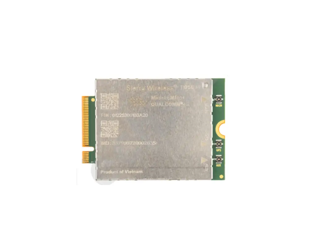
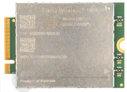
The Sierra Wireless EM7590 is a compact, lightweight, wireless modem that provides LTE, UMTS, and GNSS connectivity for M2M applications, notebook, ultrabook and tablet computers over several radio frequency bands.
Accessories
A hardware development kit is available for MC-series modules. The kit contains hardware components for evaluating and developing with the module, including:
- Development board
- Cables
- Antennas (Additional antennas may be required to support all bands.)
- Initial allotment of support hours
- Other accessories
- For over-the-air LTE testing, ensure that suitable antennas are used.
Required Connectors
Table 1-1 describes the connectors used to integrate the EM7590 PCI Express Mini Card into your host device.
Table 1-1: Required host-module connectors’
| Connnector Type | Description |
| RF cables |
|
| EDGE (52-pin) |
|
| SIM |
|
Power
Power Supply
The host provides power to the Sierra Wireless EM7590 through multiple power and ground pins. The host must provide safe and continuous power at all times; the module does not have an independent power supply, or protection circuits to guard against electrical issues.
For detailed pinout and voltage/current requirements of this module, refer to the EM7590 Product Technical Specification.
Module Power States
The module has four basic power states, as described in Table 2-1.
Table 2-1: Module Power States
| rmal (Default state) |
| | | | |
| Low power (‘Airplane mode’) |
| | | | |
| Sleep |
| | | a | |
| Disconnected |
| | | b | |
a. USB interface is suspended.
b. USB interface is disconnected.
RF Specifications
The module, based on Qualcomm’s MDM9250 baseband processor, supports data operation on LTE and UMTS networks over the bands described in Table 3-1, with LTE carrier aggregation (CA) as described in Table 3-2and Table 3-3.
Table 3-1: Supported RF Bands
RAT | Bands | ||||||||||||||||||||||||||||
| 1 | 2 | 3 | 4 | 5 | 6 | 7 | 8 | 9 | 12 | 13 | 14 | 18 | 19 | 20 | 25 | 26 | 28 | 29 | 32 | 38 | 39 | 40 | 41 | 42 | 43 | 48 | 66 | 71 | |
| LTEa | F | F | F | F | F | F | F | F | F | F | F | F | F | F | F | F | Fb | Fb | T | T | T | T | T | T | T | F | F | ||
UMTSc | Y | Y | Y | Y | Y | Y | Y | Y | |||||||||||||||||||||
GNSS |
| ||||||||||||||||||||||||||||
a. (LTE) Downlink MIMO support (2×2; 4×2) F=FDD; T=TDD Data rates: Downlink (Cat 13 with 2CA, 256QAM=400 Mbps), Uplink (Cat 13 with 2CA contiguous, 64QAM=150 Mbps)
b. Downlink only
c. UMTS (DC-HSPA+, HSPA+, HSPA, UMTS) Diversity support Data rates: Downlink (Cat 24, up to 42 Mbps), Uplink (Cat 6, up to 5.76 Mbps)
Table 3-2: Carrier Aggregation Downlink Combinations
1 Band / 2CC | 2 Bands / 2CC | 2 Bands / 2CC |
CA_1A-1A | CA_1A-3A | CA_5A-7A |
| CA_1C | CA_1A-5A | CA_5A-25A |
CA_2A-2A | CA_1A-7A | CA_5A-38A |
| CA_2C | CA_1A-8A | CA_5A-40A |
CA_3A-3A | CA_1A-18A | CA_5A-41A |
| CA_3C | CA_1A-19A | CA_5A-66A |
CA_4A-4A | CA_1A-20A | CA_7A-8A |
| CA_5A-5A | CA_1A-26A | CA_7A-12A |
| CA_5B | CA_1A-28A | CA_7A-20A |
| CA_7A-7A | CA_1A-32A | CA_7A-28A |
| CA_7B | CA_1A-38A | CA_7A-32A |
| CA_7C | CA_1A-40A | CA_7A-42A |
| CA_8B | CA_1A-41A | CA_8A-32A |
| CA_12A-12A | CA_1A-42A | CA_8A-38A |
| CA_12B | CA_2A-4A | CA_8A-39A |
| CA_25A-25A | CA_2A-5A | CA_8A-40A |
| CA_38C | CA_2A-7A | CA_8A-41A |
| CA_39C | CA_2A-12A | CA_8A-42A |
| CA_40A-40A | CA_2A-13A | CA_12A-25A |
| CA_40C | CA_2A-14A | CA_12A-66A |
| CA_41A-41A | CA_2A-28A | CA_13A-66A |
| CA_41C | CA_2A-66A | CA_14A-66A |
| CA_42C | CA_2A-71A | CA_19A-1A |
| CA_43C | CA_3A-5A | CA_19A-3A |
| CA_48C | CA_3A-7A | CA_19A-42A |
| CA_66A-66A | CA_3A-8A | CA_20A-32A |
| CA_66B | CA_3A-19A | CA_20A-40A |
| CA_66C | CA_3A-20A | CA_20A-42A |
| CA_3A-26A | CA_25A-26A | |
| CA_3A-28A | CA_26A-41A | |
| CA_3A-38A | CA_28A-38A | |
| CA_3A-40A | CA_28A-40A | |
| CA_3A-41A | CA_28A-41A | |
| CA_3A-42A | CA_28A-42A | |
| CA_4A-5A | CA_39A-41A | |
| CA_4A-7A | CA_41A-42A | |
| CA_4A-12A | CA_66A-71A | |
| CA_4A-13A | ||
| CA_4A-28A | ||
| CA_4A-71A |
Table 3-3: Carrier Aggregation Uplink Combinations.
CA_1C |
CA_3C |
CA_5B |
CA_7C |
CA_39C |
CA_41C |
CA_42C |
CA_43C |
CA_48C |
RF Connections
When attaching antennas to the module:
- Use IPEX (20449-001E (MHF4))to attach antennas to connection
points on the module.
Note: To disconnect the antenna, make sure you use the IPEX MHF4 connector removal tool to prevent damage to the module or coaxial cable assembly.
- Match coaxial connections between the module and the antenna to 50 .
- Minimize RF cable losses to the antenna; the recommended maximum cable loss for antenna cabling is 0.5 db.
- To ensure best thermal performance, mounting holes must be used to attach(ground) the device to the main PCB ground or a metal chassis.
Note: If the antenna connection is shorted or open, the modem will not sustain permanent damage.
Shielding
The module is fully shielded to protect against EMI and the shield must not be removed.
Antenna and Cabling
When selecting the antenna and cable, it is critical to RF performance to matchantenna gain and cable loss.
Choosing the Correct Antenna and Cabling
When matching antennas and cabling:
- The antenna (and associated circuitry) should have a nominal impedance of50 with a recommended return loss of better than 10 dB across each frequency band of operation.
- The system gain value affects both radiated power and regulatory (FCC, IC,CE, etc.) test results.
Designing Custom Antennas
Consider the following points when designing custom antennas:
- A skilled RF engineer should do the development to ensure that the RF performance is maintained.
Determining the Antenna’s Location
When deciding where to put the antennas:
- Antenna location may affect RF performance. Although the module is shielded to prevent interference in most applications, the placement of the antenna is still very important–if the host device is insufficiently shielded, high levels of broadband or spurious noise can degrade the module’s performance.
- Connecting cables between the module and the antenna must have 50 impedance. If the impedance of the module is mismatched, RF performance is reduced significantly.
- Antenna cables should be routed, if possible, away from noise sources (switching power supplies, LCD assemblies, etc.). If the cables are near thenoise sources, the noise may be coupled into the RF cable and into the antenna.
Disabling the Diversity Antenna
Certification testing of a device with an integrated EM7590 may require the module’s main and diversity antennas to be tested separately.
To facilitate this testing, receive diversity can be enabled/disabled using
AT commands:
- AT!RXDEN– Used to enable/disable diversity for single-cell call (no carrier aggregation).
- AT!LTERXCONTROL– Used to enable/disable paths (in carrier aggregation scenarios) after a call is set up.
Important: LTE networks expect modules to have more than one antenna enabled for proper operation. Therefore, customers must not commercially deploy their systems with the diversity antenna disabled.
Note: A diversity antenna is used to improve connection quality and reliability through redundancy. Because two antennas may experience difference interference effects (signal distortion, delay, etc.), when one antenna receives a degraded signal, the other may not be similarly affected.
Ground Connection
When connecting the module to system ground:
- Prevent noise leakage by establishing a very good ground connection to the module through the host connector.
- Connect to system ground using the two mounting holes at the top of the module.
- Minimize ground noise leakage into the RF.
Depending on the host board design, noise could potentially be coupled to the module from the host board. This is mainly an issue for host designs that have signals traveling along the length of the module, or circuitry operating at both ends of the module interconnects.
Interference and Sensitivity
Several interference sources can affect the module’s RF performance (RF desense). Common sources include power supply noise and devicegenerated RF.
RF desense can be addressed through a combination of mitigation techniques (Methods to Mitigate Decreased Rx Performance on page 13) and radiated sensitivity measurement (Radiated Sensitivity Measurement on page 14).
Note: The EM7590 is based on ZIF (Zero Intermediate Frequency) technologies. When performing EMC (Electromagnetic Compatibility) tests, there are no IF (Intermediate Frequency) components from the module to consider.
Interference From Other Wireless Devices
Wireless devices operating inside the host device can cause interference that affects the module.
To determine the most suitable locations for antennas on your host device, evaluate each wireless device’s radio system, considering the following:
- Any harmonics, sub-harmonics, or cross-products of signals generated
by wireless devices that fall in the module’s Rx range may cause spurious response, resulting in decreased Rx performance. - The Tx power and corresponding broadband noise of other wireless devices may overload or increase the noise floor of the module’s receiver, resulting in Rx desense.
The severity of this interference depends on the closeness of the other antennasto the module’s antenna. To determine suitable locations for each wireless device’s antenna, thoroughly evaluate your host device’s design.
Host-generated RF Interference
All electronic computing devices generate RF interference that can negatively affect the receive sensitivity of the module.
Proximity of host electronics to the antenna in wireless devices can contribute to decreased Rx performance. Components that are most likely to cause this include:
- Microprocessor and memory
- Display panel and display drivers
- Switching-mode power supplies
Device-generated RF Interference
The module can cause interference with other devices. Wireless devices such as AirPrime embedded modules transmit in bursts (pulse transients) for set durations (RF burst frequencies). Hearing aids and speakers convert these burst frequencies into audible frequencies, resulting in audible noise.
Methods to Mitigate Decreased Rx Performance
It is important to investigate sources of localized interference early in the design cycle. To reduce the effect of device-generated RF on Rx performance:
- Put the antenna as far as possible from sources of interference.
The drawback is that the module may be less convenient to use. - Shield the host device. The module itself is well shielded to avoid external interference. However, the antenna cannot be shielded for obvious reasons. In most instances, it is necessary to employ shielding on the components of the host device (such as the main processor and parallel bus) that have the highest RF emissions.
- Filter out unwanted high-order harmonic energy by using discrete filtering on low frequency lines.
- Form shielding layers around high-speed clock traces by using multilayer PCBs.
- Route antenna cables away from noise sources.
Radiated Spurious Emissions (RSE)
When designing an antenna for use with AirPrime embedded modules, the host device with an AirPrime embedded module must satisfy any applicable standards/local regulatory bodies for radiated spurious emission (RSE) for receive-only mode and for transmit mode (transmitter is operating).
Note that antenna impedance affects radiated emissions, which must be compared against the conducted 50-ohm emissions baseline. (AirPrime embedded modules meet the 50-ohm conducted emissions requirement.)
Radiated Sensitivity Measurement
A wireless host device contains many noise sources that contribute to a reductionin Rx performance.
To determine the extent of any receiver performance desensitization due to selfgenerated noise in the host device, over-the-air (OTA) or radiated testing is required. This testing can be performed by Sierra Wireless or you can use your own OTA test chamber for in-house testing.
Regulatory Compliance and Industry Certifications
The EM7590 module is designed to meet, and upon commercial release, will meet the requirements of the following regulatory bodies and regulations, where applicable:
- Federal Communications Commission (FCC) of the United States
- The Certification and Engineering Bureau of Industry Canada (IC)
- The National Communications Commission (NCC) of Taiwan, Republic of China
The EM7590 Embedded Module complies with the mandatory requirements described in the following standards. The exact set of requirements supported is network operatordependent.
Table 7-1: Standards Compliance
| Technology | Standards |
| LTE |
|
| UMTS |
|
a. Some auxiliary functions support Release 13
Upon commercial release, the following industry certifications will have been obtained, where applicable:
- GCF
- PTCRB
Additional certifications and details on specific country approvals may be obtained upon customer request– contact your Sierra Wireless account representative for details.
Additional testing and certification may be required for the end product with an embedded EM7590 module and are the responsibility of the OEM. Sierra Wireless offers professional services-based assistance to OEMs with the testing and certification process, ifrequired.
Important Compliance Information for North American Users
The EM7590 module, upon commercial release, will have been granted modular approval for mobile applications. Integrators may use the EM7590 module in their final products without additional FCC/IC (Industry Canada) certification if they meet the following conditions. Otherwise, additional FCC/IC approvals must be obtained.
- At least 20 cm separation distance between the antenna and the user’s body must be maintained at all times.
- To comply with FCC/IC regulations limiting both maximum RF output power and human exposure to RF radiation, the maximum antenna gain including cable loss in a mobile-only exposure condition must not exceed the limits stipulated in Table 4-1 on page 17.
- The EM7590 module may transmit simultaneously with other collocated radio transmitters within a host device, provided the following conditions are met:
· Each collocated radio transmitter has been certified by FCC/IC for mobile application.
· At least 20 cm separation distance between the antennas of the collocated transmitters and the user’s body must be maintained at all times.
· The radiated power of a collocated transmitter must not exceed the EIRP limit stipulated in Table 4-1.
Table 4-1: Antenna Gain and Collocated Radio Transmitter SpecificationsOperating mode Tx Freq Range (MHz) Max Time-Avg Cond. Power (dBm) Antenna Gain Limit (dBi) EIRP
Limits (dBm)
Standalone
Collocated
EM7590 Embedded Module
WCDMA Band 2, LTE B2
1850 1910 24 9.00 7.30 33.0 WCDMA Band 4, LTE B4 1710 1755 24 6.00 6.00 30.0 WCDMA Band 5, LTE B5 824 849 24 7.00 4.90 31.0
LTE B7
2500 2570 24 9.00 8.20 33.0 LTE B12 699 716 24 6.60 4.50 30.6
LTE B13
777 787 24 6.90 4.80 30.9 LTE B14
788 798 24 6.90 4.80 30.9
LTE B25 1850 1915 24 9.00 7.30 33.0
LTE B26
814 849 24 7.00 4.90 31.0 LTE B41 2496 2690 24 9.00 8.20 33.0
LTE B42
3400 3600 23 0.00 0.00 23.0 LTE B43 3600 3800 23 0.00 0.00 23.0
LTE B48a
3550 3700 23 0.00 0.00 23.0 LTE B66
1710 1780 24 6.00 6.00 30.0
LTE B71 663 698 24 6.40 4.30 30.4
Collocated transmitters
WLAN 2.4 GHz
2400 2500 30 WLAN 5 GHz
5150 5850 30
WLAN 6 GHz 5955 7115 30
BT
2400 2500 16
a. Important: Airborne operations in LTE Band 48 are prohibited.
- A label must be affixed to the outside of the end product into which the EM7590 module is incorporated, with a statement similar to the following:
· This device contains FCC ID: N7NEM75T
Contains transmitter module IC: 2417C-EM75T where 2417C-EM75T is the module’s certification number. - A user manual with the end product must clearly indicate the operating requirements and conditions that must be observed to ensure compliance with current FCC/IC RF exposure guidelines.
The end product with an embedded EM7590 module may also need to pass the FCC Part 15 unintentional emission testing requirements and be properly authorized per FCC Part 15.
Note: If this module is intended for use in a portable device, you are responsible for separate approval to satisfy the SAR requirements of FCC Part 2.1093 and IC RSS-102.
Appendix
For more details, several references can be consulted, as detailed below.
Website Support
Check http://source.sierrawireless.com for the latest documentation available.
Abbreviations
Table A-1: Acronyms and Definitions
| Acronym or Term | Description |
| 3GPP | 3rd Generation Partnership Project |
| BeiDou | BeiDou Navigation Satellite System A Chinese system that uses a series of satellites in geostationary and middle earth orbits toprovide navigational data. |
| BER | Bit Error Rate—A measure of receive sensitivity |
| BLER | Block Error Rate |
| dB | Decibel = 10 x log10 (P1/P2) P1 is calculated power; P2 is reference power Decibel = 20 x log10 (V1/V2) V1 is calculated voltage, V2 is reference voltage |
| dBm | A logarithmic (base 10) measure of relative power (dB for decibels); relative to milliwatts (m). A dBm value will be 30 units (1000 times) larger (less negative) than a dBW value, because of the difference in scale (milliwatts vs. watts). |
| DC-HSPA+ | Dual Carrier HSPA+ |
| EMC | Electromagnetic Compatibility |
| EMI | Electromagnetic Interference |
| FCC | Federal Communications Commission The U.S. federal agency that is responsible for interstate and foreign communications. The FCC regulates commercial and private radio spectrum management, sets rates for communications services, determines standards for equipment, and controls broadcast licensing. Consult www.fcc.gov. |
| Galileo | A European system that uses a series of satellites in middle earth orbit to provide navigational data. |
| GCF | Global Certification Forum |
| GLONASS | Global Navigation Satellite System—A Russian system that uses a series of 24 satellites in middle circular orbit to provide navigational data. |
| GNSS | Global Navigation Satellite Systems (GPS, GLONASS, BeiDou, and Galileo) |
| GPS | Global Positioning System An American system that uses a series of 24 satellites in middle circular orbit to provide navigational data. |
| Host | The device into which an embedded module is integrated |
| HSDPA | High Speed Downlink Packet Access |
| HSPA+ | Enhanced HSPA, as defined in 3GPP Release 7 and beyond |
| HSUPA | High Speed Uplink Packet Access |
| Hz | Hertz = 1 cycle/second |
| IC | Industry Canada |
| IF | Intermediate Frequency |
| IS | Interim Standard. After receiving industry consensus, the TIA forwards the standard to ANSI for approval. |
| LTE | Long Term Evolution—a high-performance air interface for cellular mobile communication systems. |
| MHz | Megahertz = 10e6 Hz |
| OEM | Original Equipment Manufacturer—a company that manufactures a product and sells it to a reseller. |
| OTA | ‘Over the air’ (or radiated through the antenna) |
| PCB | Printed Circuit Board |
| PCS | Personal Communication System A cellular communication infrastructure that uses the 1.9 GHz radio spectrum. |
| PTCRB | PCS Type Certification Review Board |
| RF | Radio Frequency |
| RSE | Radiated Spurious Emissions |
| Sensitivity (RF) | Measure of lowest power signal at the receiver input that can provide a prescribed BER/BLER/SNR value at the receiver output. |
| SNR | Signal-to-Noise Ratio |
| TIA / EIA | Telecommunications Industry Association / Electronics Industry Association. A standards setting trade organization, whose members provide communications and information technology products, systems, distribution services and professional services in the United States and around the world. Consult www.tiaonline.org. |
| UMTS | Universal Mobile Telecommunications System |
| USB | Universal Serial Bus |
| VCC | Supply voltage |
| WCDMA | Wideband Code Division Multiple Access (also referred to as UMTS) |
| ZIF | Zero Intermediate Frequency |

References
 IoT Solutions - Modules, IoT Platforms & IoT Connectivity | Sierra Wireless
-
IoT Solutions - Modules, IoT Platforms & IoT Connectivity | Sierra Wireless
 Sierra Wireless Source
-
Federal Communications Commission | The United States of America
-
Telecommunications Industry Association | TIAonline.org | Home


