
5GHUB LTE CAT 4 USB Dongle EG95
Purpose of the Document
The purpose of this document is to explain the technical specifications and manual for using the LTE Cat. 4 USB dongle.
Document History
| Version | Author | Date | Description |
| A | 5G HUB | 08.12.2020 | Initial Document |
Package contents:
LTE Cat. 4 USB Dongle Package: USB dongle with LTE & Diversity & GNSS antenna connectors.
Download
Arduino software can be downloaded from the following website: 5G-NB-IoT/KitSketches at master · 5ghub/5G-NB-IoT (github.com)
To use the board with Arduino IDE and starts running Arduino projects and sketches, install the following software:
Install Arduino IDE for Windows from the following website https://www.arduino.cc/en/Main/Software
Download and Install LTE&GNSS modem driver for Windows OS: https://github.com/5ghub/5G-NB-IoT/tree/master/Driver
Download and Install QNavigator and QCOM tools for Quectel BG95 here: https://github.com/5ghub/5G-NB-IoT/tree/master/Tools
Download and install Arduino library (5G-NB-IoT_Arduino.zip) here: https://github.com/5ghub/5G-NB-IoT
All the following software can be installed from the GitHub location here: https://github.com/5ghub/5G-NB-IoT
LTE cellular connectivity on Windows OS
General Description
Overview
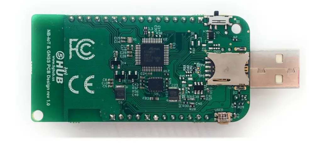
The LTE Cat 4 USB dongle is a cellular and GPS modem in an USB stick form factor. The USB dongle has UFL connectors for LTE & Diversity & GNSS antennas. The board is a powerful board that features a microcontroller and wireless modem. The microcontroller is an Atmel’s SAMD21G18A MCU which features a 32-bit ARM Cortex® M0+ core. The wireless modem is EG96 which is an embedded LTE Cat 4 wireless communication module. EG95 wireless modem provides a maximum data rate of 150Mbps downlink and 50 Mbps uplink. It provides data connectivity on LTE-FDD/HSPA/WCDMA networks. It also provides GNSS to meet customers’ specific application demands
The USB dongle provides rich sets of Internet protocols, industry-standard interfaces (USB/UART/I2C/Status Indicator) and abundant functionalities. The board offer a high integration level and enables integrators and developers to easily design their applications and take advantage of the board low power consumption, many functionalities, and USB drivers for Windows 7/8/8.1/10, Linux and Android.
The USB dongle is a rich hardware board that can be used for the 4G LTE wireless technology and enables a variety of smart applications for devices. It enables large number of applications such as wireless POS, smart metering, tracking, smart transportation, smart buildings, smart city, and smart homes.
The board is also compatible with Arduino and Arduino software (IDE). Arduino sketches and examples are provided with the kit and additional sketches can be developed and uploaded to the board.
Key Features
- Atmel ATSAMD21G18 MCU
- Quectel EG95 LTE Cat 4 module
- On-board LTE & GNSS antenna
- Supports LTE/HSPA/WCDMA
- Frequency Band B2/B4/B5/B12/B13 for LTE and B2/B4/B5 for HSPA/WCDMA
- Supports the protocols TCP/UDP/PPP/ SSL/ TLS/ FTP(S)/ HTTP(S)/ NITZ/ PING/ MQTT
- Supports SMS
- Supports GNSS technology (GPS, GLONASS, BeiDou/Compass, Galileo, QZSS)
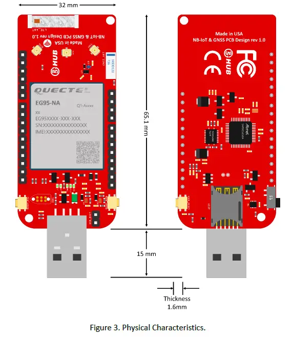
- Compact board size of 65.1 mm x 32mm
- Nano USIM card slot
- Arduino IDE Compatible
- Works with Windows, Linux, or Android
- Ready for smart applications and development (smart home, smart city, smart transportation, smart metering, smart farming, smart waste management, asset tracking, location, navigation, mapping, and timing applications). Application such as Gas Detector, Soil PH Tester, Optical Sensor, Machinery Alarm System, Irrigation Controller, Elevator, Asset Tracking Electronics, Person/Pet Tracking, Water/Gas Metering, Smart Parking System, Fire Hydrant, Smoke Alarm, Trash Bin, Street Lighting
- The board can be powered via the USB connector
- Each of the 14 general-purpose I/O pins on the board can be used for digital input or digital output using pinMode(), digitalWrite(), and digitalRead() functions. Pins used for PWM can be using analogWrite() function. All pins operate at 3.3 volts.
- Each pin can source or sink a maximum of 10 mA and has an internal pull-up resistor (disconnected by default) of 20-60 K ohm.
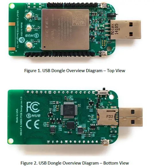
Overview Diagrams
Physical Characteristics
The width and length of the USB dongle is 32 mm (width) by 65.1 mm (length). The board have two screw holes in each corner that allows the board to be attached to a surface or case.
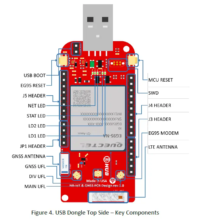
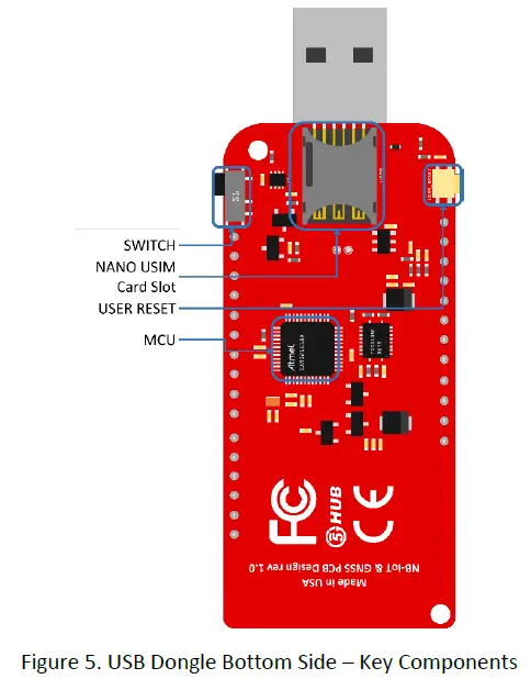
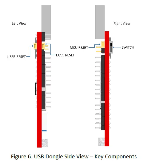
Peripherals – Key Components
Peripherals – IO Connections
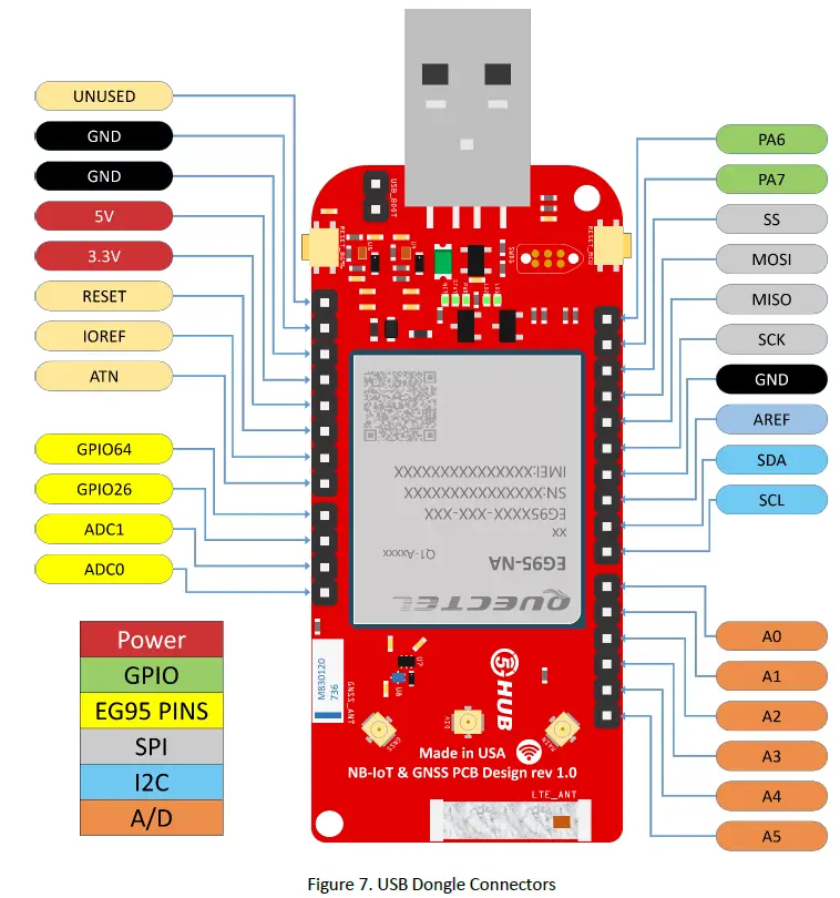
- I2C interface lines might be configured as USART interface SDA line can work then as USART TXD and SCL line can work as USART RXD)
- MOSI and SCK lines might be configured as USART interface (MOSI line can work then as USART TXD and SCK line can work as USART RXD)
Hardware Specification
| Technical Specification | |
| Microcontroller (MCU) | Atmel ATSAMD21G18, 32-Bit ARM Cortex M0+ |
| Clock Speed | 48 MHz |
| Flash Memory | 256 KB |
| SRAM | 32 KB |
| NB-IoT Module | Quectel EG95 |
| Dimension | 32 mm (width) by 65.1 mm (length) |
| Weight | 22 grams |
| Power Supply | USB (5V) |
| LED | LED1, LED2, PWR LED, Status LED, Netlight LED |
| Interfacing Logic Voltage Level (Operating Voltage) | 3.3V |
| Voltage output | 5V, 3.3V |
| RESET buttons | Two; one for MCU and one for EG95 |
| User-defined Button | 1 connected to MCU |
| USB Switch | 1 switch to connect to MCU directly or EG95 directly |
| General-purpose digital I/O Pins | 14 (A0-A5, PA6, PA7, SS, MOSI, MISO, SCK, SDA, SCL) |
| GPIO | 2 connected to EG95 |
| ADC | 2 connected to EG95 |
| USB | 1 |
| I2C | 1 |
| SPI | 1 |
| UART | 1 |
| ADC pins | 6 (8/10/12-bit ADC channels) |
| DAC pin | 1 (10-bit DAC) |
| External interrupts | 14 (All general-purpose PINs) |
| PWM pin | 6 |
| DC Current per I/O Pin | 10 mA |
| JTAG Debug | Cortex Debug Connector (Single Wire Debug) |
| USIM | Nano |
| GNSS | GPS, GLONASS, BeiDou/Compass, Galileo, QZSS |
| Antenna | 1 main, 1 Diversity, and 1 GPS |
| Band | LTE-FDD: B2/B4/B5/B12/B13 HSPA/WCDMA: B2/B4/B5 |
| Certification | GCF/ FCC/ PTCRB/ IC |
| Mobile Operator Certification | Verizon/AT&T/T-Mobile/Telus/U.S. Cellular/Rogers/Telus |
Notes:
- UART can be programmed through any of general-purpose pins.
- SPI can be programmed through any of general-purpose pins.
PIN Description
| PIN | DIRECTION | Description |
| USB Connector | I | The USB dongle is powered from the USB port (3.8V-5V) |
| LED1 (USER) | O | LED which can be controlled from MCU (D25). When the pin is HIGH value, the LED is on, when the pin is LOW, it is off |
| LED2 (USER) | O | LED which can be controlled from MCU (D26). When the pin is HIGH value, the LED is on, when the pin is LOW, it is off |
| LED (NET) | O | Indicate the EG95 operation status |
| LED (STAT) | O | Indicate the EG95 network activity status |
| MCU RESET button | I | Reset the MCU |
| EG95 RESET button | I | Reset the EG95 module |
| User Button | I | Connected to digital pin, D0, of MCU and can be used for user- defined purposes |
| USB Switch | I | 1 switch to connect to MCU directly or EG95 directly |
| IOREF | O | Provides the voltage reference with which the MCU operates. A device can read the IOREF pin voltage and select the appropriate power source or enable voltage translators on the outputs for working with the 5V or 3.3V |
| 3.3V | O | 3.3V generated by the on-board regulator. Maximum current drawn is 3A. The regulator also provides power to the MCU and EG95 |
| 5V | O | 5V generated from the board. The board is supplied with power from USB connector (typical 5V) |
| GND | Ground | |
| A0 | IO | Six analog inputs which can provide up to 12 bits of resolution (i.e. 4096 different values). By default, each input measures from ground to 3.3 volts, though is it possible to change the upper end of their range using the AREF pin A0 can also be used as a DAC output and provides a 10 bit voltage output with analo gWr it e () function Analog pins can be used as GPIOs |
| A1 | IO | |
| A2 | IO | |
| A3 | IO | |
| A4 | IO | |
| A5 | IO | |
| SCL | IO | I2C. The SCL (clock line). Can be used as GPIO |
| SDA | IO | I2C. The SDA (data line). Can be used as GPIO |
| AREFA | I | Input reference voltage for the analog inputs used for either he ADC or the DAC |
| SCK | IO | SPI Interface. Can be used as GPIO |
| MISO | IO | SPI Interface. Can be used as GPIO |
| MOSI | IO | SPI Interface. Can be used as GPIO |
| SS | IO | SPI Interface. Can be used as GPIO |
| PA7 | IO | GPIO. Can be used as GPIO |
| PA6 | IO | GPIO. Can be used as GPIO |
| Cortex Debug Connector | IO | Using Single Wire Debug to burn bootloader and debug the board |
| ADC0 | I | Connected to EG95. General-purpose analogue to digital converter |
| ADC1 | I | Connected to EG95. General-purpose analogue to digital converter |
| GPIO26 | IO | Connected to EG95. General-purpose IO |
| GPIO64 | IO | Connected to EG95. General-purpose IO |
| USIM | I | Used to insert a Nano USIM. Connected to EG95 |
| USB Boot | I | Connected to EG95. Force the EG95 to enter emergency download mode |
Precaution
The USB dongle runs at 3.3V. The maximum voltage that the I/O pins can tolerate is 3.3V. Applying voltages higher than 3.3V to any I/O pin could damage the board
EG95 chipset
All functionality of the BG95 shipset shall be implemented excluding the following features. That is, the following features are not supported [1][2].
– Audio, Earphone, and Codes are not supported.
– PCM and I2C are not supported
– PSM_IND and AP_READY are not supported
Interface between SAM21D and EG95
The Microcontroller communicates with the EG95 through UART interfaces:
– UART1: (PA12/PA13/PA14/PA15). Used for data transmission and AT command communication 115200bps by default. The default frame format is 8N1 (8 data bits, no parity, 1 stop bit) Support RTS and CTS hardware flow control.
– UART3: (PB23/PB22). Used for outputting GNSS data or NEMA sentences 115200bps baud rate.
References
- Quectel_EG95_Hardware_Design_V1.6.pdf
- Quectel_EG95_Reference_Design_Rev.A_20180209.pdf
- Quectel_Antenna_Design_Note_V2.0.pdf
- Quectel_RF_Layout_Application_Note_V2.2.pdf
- Quectel_QFlash_User_Guide_V2.3
- Arduino IDE, https://www.arduino.cc/en/Main/Software
- Arduino IDE, https://www.arduino.cc/en/Guide/ArduinoZero
- Microchip, “Low-Power, 32-bit Cortex-M0+ MCU with Advanced Analog and PWM”


