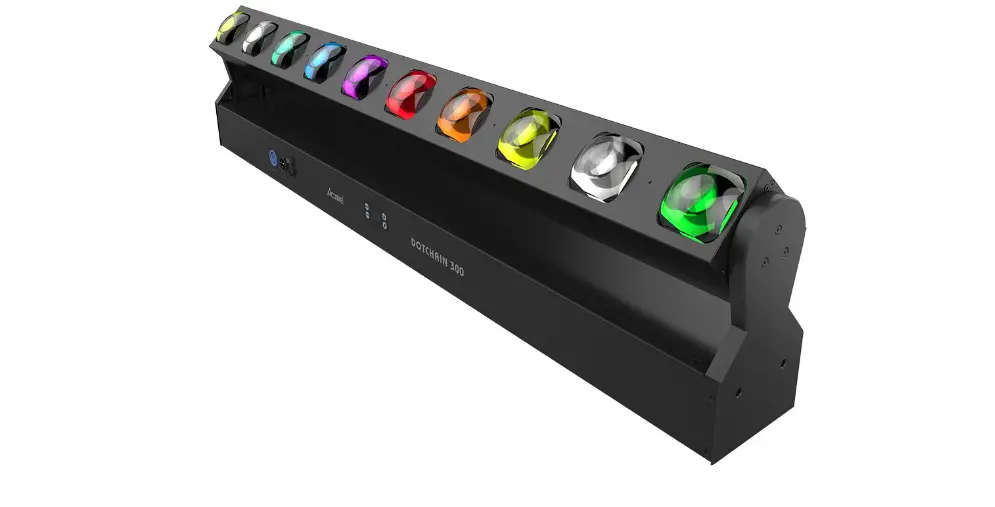
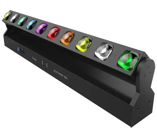
ACME DOTCHAIN 300 LED Bar Light
Safety Instructions
Please read the instruction carefully which includes important information about the installation, usage and maintenance.
WARNING
Please keep this User Manual for future consultation. If you sell the unit to another user, be sure that they also receive this manual.
Important:
Damages caused by the disregard of this user manual are not subject to warranty. The dealer will not accept liability for any resulting defects or problems.
- Unpack and check carefully to ensure that there is no transportation damage before using the unit.
- This product is for indoor use only. Use only in a dry location.
- DO install and operate by qualified operator.
- DO NOT allow children to operate the fixture.
- Use safety chain when fixing the unit. Handle the unit by carrying its base instead of head only.
- The unit must be installed in a location with adequate ventilation, at least 50cm from adjacent surfaces.
- Be sure that no ventilation slots is blocked, otherwise the unit will be overheated.
- Before operation, ensure that you are connecting this product to the proper voltage in accordance with the specifications in this manual or on the product’s specification label.
- It’s important to ground the yellow/green conductor to earth in order to avoid electric shock.
- Minimum ambient temperature TA: 0℃. Maximum ambient temperature TA: 40℃. Do not operate this product at a lower or higher temperature.
- DO NOT connect the device to any dimmer pack.
- Keep flammable materials away from the fixture while operating to avoid fire hazard.
- Make sure the power cord is not crimped or damaged; replace it immediately if damaged.
- Unit’s surface temperature may reach up to 55℃. DO NOT touch the housing bare-handed during its operation.
- Avoid any flammable liquids, water or metal from entering the unit. Once it happens, cut off the mains power immediately.
- DO NOT operate in a dirty or dusty environment. DO clean the fixture regularly.
- DO NOT touch any wire during operation as there might be a hazard of electric shock.
- Avoid entanglement of the power cord with other wires.
- The minimum distance to objects/surface must be more than 0.5 meters.
- In the event of serious operating problem, stop using the unit immediately.
- Never turn on and off the unit time after time.
- The housing, the lenses, or the ultraviolet filter must be replaced if they are visibly damaged.
- DO NOT open the housing as there are no user serviceable parts inside.
- DO NOT attempt to operate this unit if it becomes damaged. DO NOT attempt any repairs yourself. Repairs carried out by unskilled people can lead to damage or malfunction. Please contact the nearest authorized technical assistance center if needed.
- Disconnect this product from its power source before servicing.
- DO use the original packaging if the device is to be transported.
- Avoid direct eye exposure to the light source while the product is on.
- DO NOT operate this product if you see damage on the housing, shields, or cables. Have the damaged parts replaced by an authorized technician at once.
Installation:
The fixture should be fixed on the clamp. Always ensure that the unit is firmly fixed to avoid vibration and slipping off during operation. Ensure that the trussing or area of installation must be able to hold 10 times the weight without any deformation. Always install a safety cable that can hold at least 12 times the weight of the fixture when installing.
DO install and operate by qualified operator. It must be installed in a place where there is out of the reach of people.
Technical Specifications
- Power Voltage: 180-240V~ 50/60Hz
- Power Consumption: 180W
- Light Source: 10x20W RGBW LED
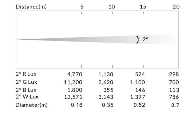
- Beam Angle: 2°
- Fixture Rotation Angle Range: 0°-220°
- Control: DMX Channel: 46/14/9 Channels
- Control Mode: DMX512, RDM Firmware
- Construction: Upgrade via DMX link
- Display: OLED display
- Data In/Out: 3-pin XLR (5-pin XLR is optional)
- Power In/Out: Power Connector in
- Protection Rating: IP20
- Features: 10 LEDs can be controlled individually Smooth dimming from 0-100% Outstanding strobe effect with variable speed
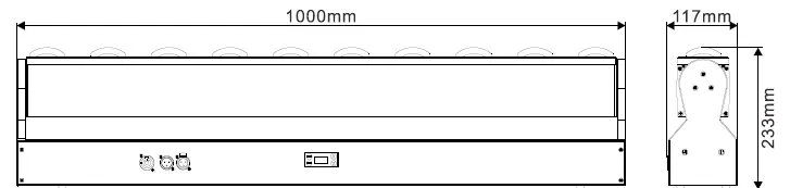
- Dimension/Weight: 1000x117x233mm, 10.4kgs 39.4″x4.6″x9.2″in, 22.9lbs

Photometric Diagram:
Control Panel
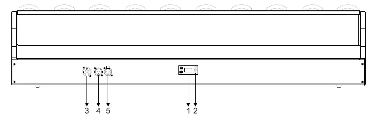
- DISPLAY: To show the various menus and the selected functions
- Button:
MENU To select the programming functions UP To go backward in the selected functions DOWN To go forward in the selected functions ENTER To confirm the selected functions - POWERCON IN: To connect to supply power
- DMX IN:
For DMX512 link, use 3-pin XLR cable to link the unit and DMX controller (5-pin XLR is optional) - DMX OUT:
For DMX 512 link, use 3-pin XLR cable to link the next units (5-pin XLR is optional)
How to Set the Unit
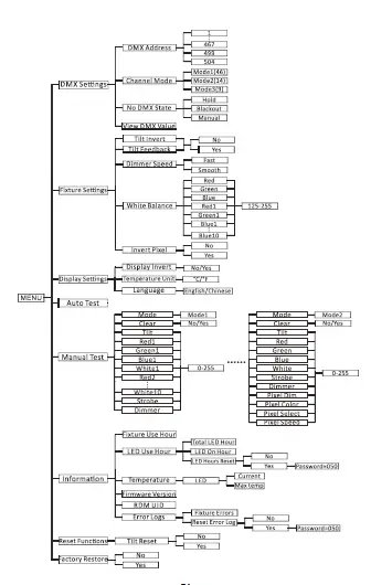
Main Function
Turn on the unit, press the MENU button into menu mode, and press the UP/DOWN button until the required function is shown on the monitor. Select the function by pressing the ENTER button. Use the UP/DOWN button to choose the submenu, press the ENTER button to store and automatically return to the last menu. Press the MENU button or let the unit idle 30 seconds to exit menu mode.
The main functions are shown below:
DMX Settings
To select DMX Settings, press the ENTER button to confirm, use the UP/DOWN button to select DMX Address, Channel Mode, No DMX State or View DMX Value.
DMX Address
To select DMX Address, press the ENTER button to confirm. Use the UP/DOWN button to adjust the address from 001 to 467/499/504, press the ENTER button to store. Press the MENU button back to the last menu or let the unit idle 30 seconds to exit menu mode.
Channel Mode
To select Channel Mode, press the ENTER button to confirm. Use the UP/DOWN button to select Mode1(46), Mode2(14) or Mode3(9), press the ENTER button to store. Press the MENU button back to the last menu or let the unit idle 30 seconds to exit menu mode.
No DMX State
To select No DMX State, press the ENTER button to confirm. Use the UP/DOWN button to select Hold(fixture continues to obey the last command it received Via DMX if DMX signal stops), Blackout(fixture blacks out if DMX signal stops) or Manual(the fixture will automatically read the DMX value in the “Manual Test” menu for operation after selecting this mode), press the ENTER button to store. Press the MENU button back to the last menu or let the unit idle 30 seconds to exit menu mode.
View DMX Value
To select View DMX Value, press the ENTER button to confirm. Use the UP/DOWN button to view the DMX channel value. Press the MENU button back to the last menu or let the unit idle 30 seconds to exit menu mode.
Fixture Settings
To select Fixture Settings, press the ENTER button to confirm. Use the UP/DOWN buttons to select Tilt Invert, Tilt Feedback, Dimmer Speed, White Balance or Invert Pixel.
Tilt Invert
To select Tilt Invert, press the ENTER button to confirm. Use the UP/DOWN button to select No or Yes, press the ENTER button to store. Press the MENU button back to the last menu or let the unit idle 30 seconds to exit menu mode.
Tilt Feedback
To select Tilt Feedback, press the ENTER button to confirm. Use the UP/DOWN button to select No or Yes, press the ENTER button to store. Press the MENU button back to the last menu or let the unit idle 30 seconds to exit menu mode.
Dimmer Speed
To select Dimmer Speed, press the ENTER button to confirm. Use the UP/DOWN button to select Fast or Smooth, press the ENTER button to store. Press the MENU button back to the last menu or let the unit idle 30 seconds to exit menu mode.
White Balance
To select White Balance, press the ENTER button to confirm. Use the UP/DOWN button to select Red, Green, Blue, Red1, Green1, Blue1…… or Blue10, press the ENTER button to confirm, use the UP/DOWN button to adjust the value from 125 to 255, press the ENTER button to store. Press the MENU button back to the last menu or let the unit idle 30 seconds to exit menu mode.
Invert Pixel
To select Invert Pixel, press the ENTER button to confirm. Use the UP/DOWN button to select No or Yes, press the ENTER button to store. Press the MENU button back to the last menu or let the unit idle 30 seconds to exit menu mode.
Display Settings
To select Display Settings, press the ENTER button to confirm, use the UP/DOWN button to select Display Invert, Temperature Unit or Language.
Display Invert
Select Display Invert, press the ENTER button to confirm. Use the UP/DOWN button to select No(normal display) or Yes(invert display), press the ENTER button to store. Press the MENU button back to the last menu or let the unit idle 30 seconds to exit menu mode.
Temperature Unit
Select Temperature Unit, press the ENTER button to confirm. Use the UP/DOWN button to select ℃ or ℉, press the ENTER button to store. Press the MENU button back to the last menu or let the unit idle 30 seconds to exit menu mode.
Language
Select Language, press the ENTER button to confirm. Use the UP/DOWN button to select English or Chinese, press the ENTER button to store. Press the MENU button back to the last menu or let the unit idle 30 seconds to exit menu mode.
Auto Test
Select Auto Test, press the ENTER button to confirm, the unit will run built-in programs to automatically test its functions. Press the MENU button back to the last menu or exit menu mode after auto test.
Manual Test
Select Manual Test, press the ENTER button to confirm, the present channel will show on the display, use the UP/DOWN button to select Mode(1 or 2), press the ENTER button to confirm. When Mode 1 is selected, use the UP/DOWN button to select Clear, Tilt, Red1, Green1, Blue1, let the unit idle 30 seconds to exit menu mode.
Language
Select Language, press the ENTER button to confirm. Use the UP/DOWN button to select English or Chinese, press the ENTER button to store. Press the MENU button back to the last menu or let the unit idle 30 seconds to exit menu mode.
Auto Test
Select Auto Test, press the ENTER button to confirm, the unit will run built-in programs to automatically test its functions. Press the MENU button back to the last menu or exit menu mode after auto test.
Manual Test
Select Manual Test, press the ENTER button to confirm, the present channel will show on the display, use the UP/DOWN button to select Mode(1 or 2), press the ENTER button to confirm. When Mode 1 is selected, use the UP/DOWN button to select Clear, Tilt, Red1, Green1, Blue1, UP/DOWN buttons to specify a value for the chosen effect from 0 to 255, press the ENTER button to store. When Mode 2 is selected, use the UP/DOWN button to select Clear, Tilt, Red, Green, Blue, White, Strobe, Dimmer, Pixel Dim, Pixel Color, Pixel Select or Pixel Speed, press the ENTER button to confirm. Use the UP/DOWN buttons to specify a value for the chosen effect from 0 to 255, press the ENTER button to store, the fixture will run as the channel value indicates. Press the MENU button back to the last menu or exit menu mode idling 30 seconds.
(The fixture will return to the previous DMX state after exiting Manual Test menu and the Manual Test parameters will be automatically saved after power off and restart.)
Information
To select Information, press the ENTER button to confirm, use the UP/DOWN button to select Fixture Use Hour, LED Use Hour, Temperature, Firmware Version, RDM UID or Error Logs.
Fixture Use Hour
Select Fixture Use Hour, press the ENTER button to confirm, fixture use hour will show on the display, press the MENU button to exit.
LED Use Hour
To select LED Use Hour, press the ENTER button to confirm, use the UP/DOWN button to select Total LED Hour, LED On Hour or LED Hours Reset, press the ENTER button to store. Select LED Hours Reset, press the ENTER button to confirm. Use the UP/DOWN button to select No or Yes, press the ENTER button to store. Select Yes, press the ENTER button to confirm. Use the UP/DOWN button to set the password 050 to reset the LED hours, press the ENTER button to store. Press the MENU button back to the last menu or exit menu mode let the unit idle 30 seconds.
Temperature
Select Temperature, press the ENTER button to confirm, use the UP/DOWN button to select LED, press the ENTER button to store, LED’s current temperature or max temperature will show on the display, press the MENU button to exit.
Firmware Version
Select Firmware Version, press the ENTER button to confirm, firmware version will show on the display, press the MENU button back to exit.
RDM UID
Select RDM UID, press the ENTER button to confirm, RDM UID will show on the display, press the MENU button back to exit.
Error Logs
Select Error Logs, press the ENTER button to confirm. Use the UP/DOWN button to select Fixture Errors or Reset Error Log, press the ENTER button to store. Select Reset Error Log, press the ENTER button to confirm. Use the UP/DOWN button to select No or Yes, press the ENTER button to store. Select Yes, press the ENTER button to confirm. Use the UP/DOWN button to set the password 050, press the ENTER button to store. Press the MENU button back to the last menu or let the unit idle 30 seconds to exit menu mode.
Reset Functions
To select Reset Functions, press the ENTER button to confirm, use the UP/DOWN button to select Tilt Reset.
Tilt Reset
Select Tilt Reset, press the ENTER button to confirm, use the UP/DOWN button to select No or Yes(the unit will run built-in program to reset tilt to its home positions), press the ENTER button to store. Press the MENU button to exit.
Factory Restore
To select Factory Restore, press the ENTER button to confirm, use the UP/DOWN button to select No(normal) or Yes (the fixture will reset to factory settings), press ENTER button to store. Press the MENU button to exit.
RDM FUNCTIONS
Select the MANUFACTURER menu to display the manufacturer of the fixture.
Select the SOFTWARE VERSION menu and the program version number of the fixture will be displayed.
Select the DMX START ADDRESS menu to change the DMX 512 address (001-512).
Select the DEVICE MODEL DESCRIPTION menu to display the model of the fixture.
Select the DEVICE LABEL menu to change the model of the fixture.
Select the DMX PERSONALITY menu to set the channel mode of the fixture (46/14/9 channel). Select the DMX PERSONALITY DESCRIPTION menu to display the current channel mode of the fixture.
Select the DEVICE HOURS menu to display the running time of the fixture.
Select the TILT INVERT menu and the fixture will run the tilt invert mode.
Select the RESET DEVICE menu, the WARM RESET/COLD RESET option will be displayed. When WARM RESET is selected, the fixture will start a warm reset, and exit when COLD RESET is selected.
Home Position Adjustment
Press the MENU button into menu mode, then press the ENTER button for about 3 seconds into offset mode to adjust the home position. Select the function by pressing the ENTER button. Use the UP/DOWN button to choose the submenu, press the ENTER button to store and automatically return to the last menu. Press MENU button to exit.
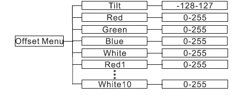
Tilt
Enter offset mode, Select Tilt, press the ENTER button to confirm, the present position will blink on the display, use the UP/DOWN button to offset the value from -128 to 127, press the ENTER button to store. Press the MENU button to exit.
Red
Enter offset mode, Select Red, press the ENTER button to confirm, the present position will blink on the display, use the UP/DOWN button to offset the value from 0 to 255, press the ENTER button to store. Press the MENU button to exit.
Green
Enter offset mode, Select Green, press the ENTER button to confirm, the present position will blink on the display, use the UP/DOWN button to offset the value from 0 to 255, press the ENTER button to store. Press the MENU button to exit.
Blue
Enter offset mode, Select Blue, press the ENTER button to confirm, the present position will blink on the display, use the UP/DOWN button to offset the value from 0 to 255, press the ENTER button to store. Press the MENU button to exit.
White
Enter offset mode, Select White, press the ENTER button to confirm, the present position will blink on the display, use the UP/DOWN button to offset the value from 0 to 255, press the ENTER button to store. Press the MENU button to exit.
Red1
Enter offset mode, Select Red1, press the ENTER button to confirm, the present position will blink on the display, use the UP/DOWN button to offset the value from 0 to 255, press the ENTER button to store. Press the MENU button to exit.
White10
Enter offset mode, Select White10, press the ENTER button to confirm, the present position will blink on the display, use the UP/DOWN button to offset the value from 0 to 255, press the ENTER button to store. Press the MENU button to exit.
Control by Universal DMX Controller
DMX512 Connections
- At last unit, the DMX cable has to be terminated with a terminator. Solder a 120-ohm 1/4W resistor between pin 2(DMX-) and pin 3(DMX+) into a 3-pin XLR-plug and plug it in the DMX-output of the last unit.
- Connect the unit together in a “daisy chain” by XLR plug cable from the output of the unit to the input of the next unit. The cable can only be used in series and cannot be connected in parallel. DMX 512 is a very high-speed signal. Inadequate or damaged cables, soldered joints or corroded connectors can easily distort the signal and shut down the system.
The DMX output and input connectors are pass-through to maintain the DMX circuit, when one of the units’ power is disconnected. - Each lighting unit needs to have a DMX address to receive the data by the controller. The address number is between 1-512.
- The end of the DMX 512 system should be terminated to reduce signal errors.
- 3 pin XLR connectors are more popular than 5 pins XLR.
3 pin XLR: Pin 1: GND, Pin 2: Negative signal (-), Pin 3: Positive signal (+)
5 pin XLR: Pin 1: GND, Pin 2: Negative signal (-), Pin 3: Positive signal (+), Pin4, Pin5 not used.
Address Setting
If you use a universal DMX controller to control the units, you have to set DMX address from 1 to 512 so that the units can receive DMX signal.
Press the MENU button to enter menu mode, select DMX Settings, press the ENTER button to confirm, use the UP/DOWN button to select DMX Address, press the ENTER button to confirm, the present address will blink in the display, use the UP/DOWN button to adjust the address from 001 to 512, press the ENTER button to store. Press the MENU button back to the last menu or let the unit idle 30 seconds to exit menu mode.
Please refer to the following diagram to address your DMX512 channel for the first 4 units.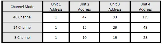
DMX512 Configuration
Please control the fixture by referring to the configurations below Attentions:
- The unit will maintain the last condition until reset if you cut-off the DMX signal.
- For the channel Function, keep the value for about 3 seconds, then the corresponding function will take into effect.
46 Channels Mode(Mode 1):
| CHANNEL | VALUE | FUNCTION |
| 1 | 000-255 | TILT 0°”220° |
| 2 | 000-255 | TILT FINE |
| 3 | 000-255 | TILT SPEED Fast to Slow |
| 4 | RED1 | |
| 000-255 | 0%100% | |
| 5 | 000-255 | GREEN1 0%100% |
| 6 | 000-255 | BLUE1 0%100% |
| 7 | 000-255 | WHITE1 0%100% |
| 8 | 000-255 | RED2 0%100% |
| 9 | 000-255 | GREEN2 0%100% |
| 10 | 000-255 | BLUE2 0%100% |
| 11 | 000-255 | WHITE2 0%100% |
| 12 | 000-255 | RED3 0%100% |
| 13 | 000-255 | GREEN3 0%100% |
| 14 | 000-255 | BLUE3 0%100% |
| 15 | 000-255 | WHITE3 0%100% |
| 16 | 000-255 | RED4 0%100% |
| 17 | 000-255 | GREEN4 0%100% |
| 18 | 000-255 | BLUE4 0%100% |
| 19 | 000-255 | WHITE4 0%100% |
| 20 | 000-255 | RED5 0%100% |
| 21 | 000-255 | GREEN5 0%100% |
| 22 | 000-255 | BLUE5 0%100% |
| 23 | 000-255 | WHITE5 0%100% |
| 24 | 000-255 | RED6 0%100% |
| 25 | 000-255 | GREEN6 0%100% |
| 26 | 000-255 | BLUE6 0%100% |
| 27 | 000-255 | WHITE6 0%100% |
| 28 | 000-255 | RED7 0%100% |
| 29 | 000-255 | GREEN7 0%100% |
| 30 | 000-255 | BLUE7 0%100% |
| 31 | 000-255 | WHITE7 0%100% |
| 32 | 000-255 | RED8 0%100% |
| 33 | 000-255 | GREEN8 0%100% |
| 34 | 000-255 | BLUE8 0%100% |
| 35 | 000-255 | WHITE8 0%100% |
| 36 | 000-255 | RED9 0%100% |
| 37 | 000-255 | GREEN9 0%100% |
| 38 | 000-255 | BLUE9 0%100% |
| 39 | 000-255 | WHITE9 0%100% |
| 40 | 000-255 | RED10 0%100% |
| 41 | 000-255 | GREEN10 0%100% |
| 42 | 000-255 | BLUE10 0%100% |
| 43 | 000-255 | WHITE10 0%100% |
| 44 | 000-007 008-015 | STROBE Close Open |
| 016-131 132-139 140-181 182-189 190-231 232-239 240-247 248-255 | Strobe from Slow to Fast Open Fast Close Slow Open Open Fast Open Slow Close Open Random Strobe Open | |
| 45 | 000-255 | DIMMER 0%100% |
|
46 | 000-029 030-039 040-049 050-059 060-069 070-079 080-089 090-099 100-109 110-119 120-139 140-149 150-159 160-199 200-209 210-219 220-229 230-255 | FUNCTION Null Null Null Null Null Null Null Null Null Null Null Null Null Null Tilt Reset Dimmer Speed: Fast Dimmer Speed: Smooth Null |
14 Channels Mode(Mode 2):
| CHANNEL | VALUE | FUNCTION |
| 1 | 000-255 | TILT 0°”220° |
| 2 | 000-255 | TILT FINE |
| 3 | 000-255 | TILT SPEED Fast to Slow |
| 4 | 000-255 | RED 0%”100% |
| 5 | 000-255 | GREEN 0%100% |
| 6 | 000-255 | BLUE 0%100% |
| 7 | 000-255 | WHITE 0%100% |
|
8 | 000-007 008-015 016-131 132-139 140-181 182-189 190-231 232-239 240-247 248-255 | STROBE Close Open Strobe from Slow to Fast Open Fast Close Slow Open Open Fast Open Slow Close Open Random Strobe Open |
| 9 | 000-255 | DIMMER 0%100% |
| 10 | 000-255 | PIXEL EFFECT DIMMER 0%100% |
|
11 | 000-009 010-014 015-019 020-024 025-029 030-034 035-039 040-044 045-049 050-054 055-059 060-064 065-069 070-074 075-079 080-084 085-089 090-094 095-099 100-104 105-109 | PIXEL EFFECT COLOR Open LEE 790-Moroccan Pink LEE 157-Pink LEE 332-Special Rose Pink LEE 328-Follies Pink LEE 345-Fuchsia Pink LEE 194-Surprise Pink LEE 181-Congo Blue LEE 071-Tokyo Blue LEE 120-Deep Blue LEE 079-Just Blue LEE 132-Medium Blue LEE 200-Double CT Blue LEE 161-State Blue LEE 201-Full CT Blue LEE 202-Half CT Blue LEE 117-Steel Blue LEE 353-Lighter Blue LEE 118-Light Blue LEE 116-Medium Blue Green LEE 124-Dark Green |
| 110-114 | LEE 139-Primary Green | |
| 115-119 | LEE 089-Moss Green | |
| 120-124 | LEE 122-Fern Green | |
| 125-129 | LEE 738-JAS Green | |
| 130-134 | LEE 088-Lime Green | |
| 135-139 | LEE 100-Spring Yellow | |
| 140-144 | LEE 104-Deep Amber | |
| 145-149 | LEE 179-Chrome Orange | |
| 150-154 | LEE 105-Orange | |
| 155-159 | LEE 021-Gold Amber | |
| 160-164 | LEE 778-Millennium Gold | |
| 165-169 | LEE 135-Deep Gold Amber | |
| 170-174 | LEE 164-Flame Red | |
| 175-179 | Open | |
| 180-201 | Clockwise Rotation, Fast to Slow | |
| 202-207 | Stop | |
| 208-229 | Counter-clockwise Rotation, Slow to Fast | |
| 230-234 | Open | |
| 235-239 | Random Color: Fast | |
| 240-244 | Random Color: Medium | |
| 245-249 | Random Color: Slow | |
| 250-255 | Open | |
| PIXEL EFFECT | ||
| 000-003 | Open | |
| 004-007 | Built-in Effect1 | |
| 008-011 | Built-in Effect2 | |
| 012-015 | Built-in Effect3 | |
| 016-019 | Built-in Effect4 | |
| 020-023 | Built-in Effect5 | |
| 024-027 | Built-in Effect6 | |
| 028-031 | Built-in Effect7 | |
| 032-035 | Built-in Effect8 | |
| 12 | 036-039 040-043 | Built-in Effect9 Built-in Effect10 |
| 044-047 | Built-in Effect11 | |
| 048-051 | Built-in Effect12 | |
| 052-055 | Built-in Effect13 | |
| 056-059 | Built-in Effect14 | |
| 060-063 | Built-in Effect15 | |
| 064-067 | Built-in Effect16 | |
| 068-071 | Built-in Effect17 | |
| 072-075 | Built-in Effect18 | |
| 076-079 | Built-in Effect19 | |
| 080-083 | Built-in Effect20 | |
| 084-087 | Built-in Effect21 | |
| 088-091 | Built-in Effect22 | |
| 092-095 | Built-in Effect23 | |
| 096-099 | Built-in Effect24 | |
| 100-103 | Built-in Effect25 | |
| 104-107 | Built-in Effect26 | |
| 108-111 | Built-in Effect27 | |
| 112-115 | Built-in Effect28 | |
| 116-119 | Built-in Effect29 | |
| 120-123 | Built-in Effect30 | |
| 124-127 | Built-in Effect31 | |
| 128-131 | Built-in Effect32 | |
| 132-135 | Built-in Effect33 | |
| 136-255 | Null | |
| PIXEL EFFECT SPEED | ||
| 13 | 000 001-127 | Null Slow to Fast without Fade |
| 128-255 | Slow to Fast with Fade | |
| FUNCTION | ||
| 000-029 | Null | |
| 030-039 | Null | |
| 040-049 | Null | |
| 050-059 | Null | |
| 060-069 | Null | |
| 070-079 | Null | |
| 080-089 | Null | |
| 090-099 | Null | |
| 14 | 100-109 | Null |
| 110-119 | Null | |
| 120-139 | Null | |
| 140-149 | Null | |
| 150-159 | Null | |
| 160-199 | Null | |
| 200-209 | Tilt Reset | |
| 210-219 | Dimmer Speed: Fast | |
| 220-229 | Dimmer Speed: Smooth | |
| 230-255 | Null | |
9 Channels Mode(Mode 3):
| CHANNEL | VALUE | FUNCTION |
| 1 | 000-255 | TILT 0°”220° |
| 2 | 000-255 | TILT FINE |
| 3 | 000-255 | TILT SPEED Fast to Slow |
| 4 | 000-255 | RED 0%”100% |
| 5 | 000-255 | GREEN 0%”100% |
| 6 | 000-255 | BLUE 0%”100% |
| 7 | 000-255 | WHITE 0%”100% |
|
8 | 000-007 008-015 016-131 132-139 140-181 182-189 190-231 232-239 240-247 248-255 | STROBE Close Open Strobe from Slow to Fast Open Fast Close Slow Open Open Fast Open Slow Close Open Random Strobe Open |
| 9 | 000-255 | DIMMER 0%”100% |
Error Information
Error codes are shown continuously in the display when the fixture fails and they will not disappear until the fixture is repaired.
- Tilt Encode Error
Check whether the encoder on the tilt is damaged.
Check whether the lead connecting the encoder on the tilt and the PCB board is in poor contact or disconnected. - LED Timeout Use
- LED Too Hot Off
When the fixture temperature reaches 81℃, it will automatically turn off to protect the fixture. - LED Temp. Error
Check whether the temperature detecting board is normal. - Check whether the components of the temperature detecting board are damaged.
- Check whether the lead on the temperature detecting board is installed in place or disconnected.
Troubleshooting
Following are a few common problems that may occur during operation. Here are some suggestions for troubleshooting:
A. The unit does not work and no light
- Check the connected power.
- Measure the voltage.
- Check the power indicator to see whether it can be lit up or not.
B. Not responding to the DMX controller
- Check whether the DMX connectors and the DMX cables are connected correctly.
- Check whether the DMX address is correctly set.
- If the intermittent DMX signal problem occurs, check whether the XLR socket and the signal cable are well connected.
- Try it with another DMX controller.
- Check whether the DMX cables run near or alongside to the high-voltage cables, which may damage or interfere with the signal circuit.
C. One of the channels is not working well
- The stepper motor might be damaged or the cable connected to the PCB might be broken.
- The motor’s drive IC on the PCB might be out of condition.
Fixture Cleaning
It is absolutely essential that the fixture is kept clean to ensure the maximum light-output and allow the fixture to function reliably throughout its life. The fixture must be cleaned regularly to avoid dust, dirt and smoke-fluid residues building up on or within the fixture. The cleaning frequency depends on the application environment. Clean the fixture immediately if the dust enters it to avoid damage to the optical lens due to excessive dust.
- A soft lint-free cloth moistened with any good glass cleaning fluid is recommended, under no circumstances should solvents be used.
- Always dry the parts carefully.
- Clean the external optical lens at least every 20 days.
Innovation, Quality, Performance


