Hytera Communications HR65XU1 Digital Repeater

Product Layout
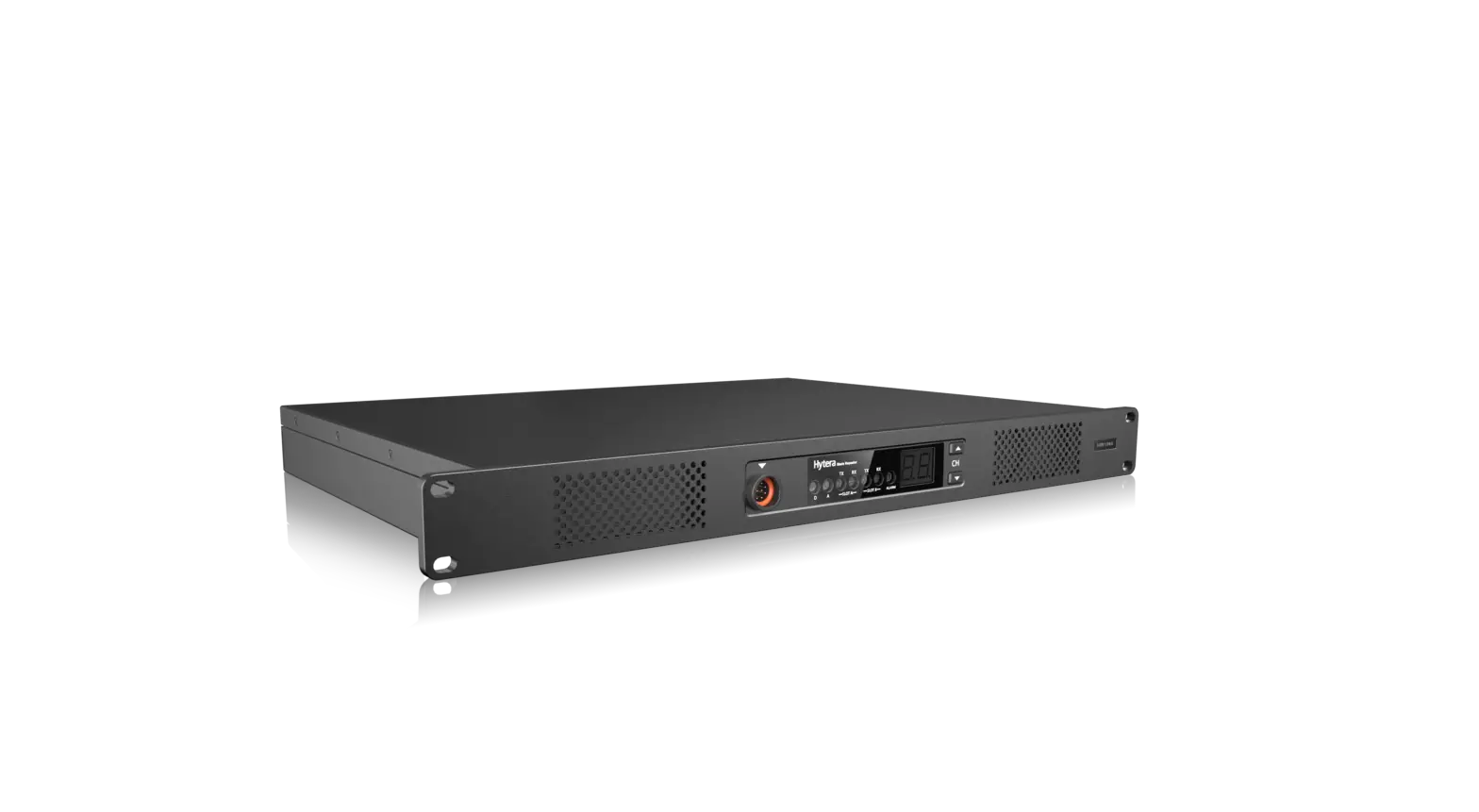
Full View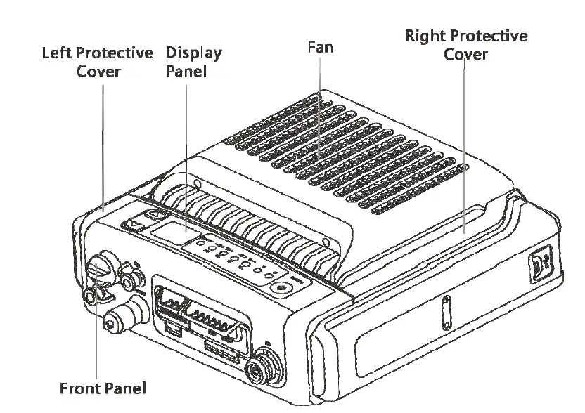
Front Panel 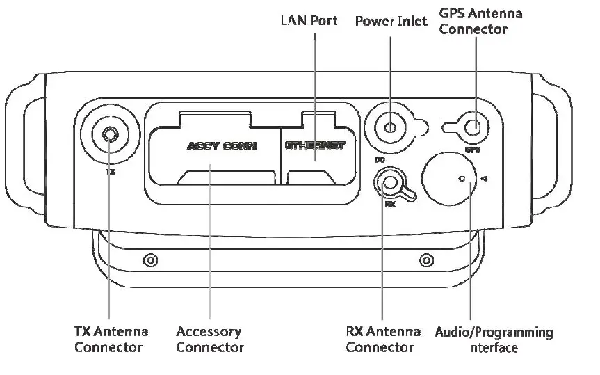
Product Layout
Full View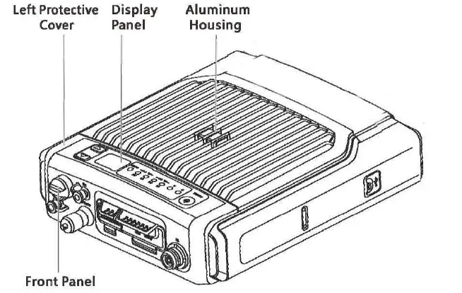
Front Panel 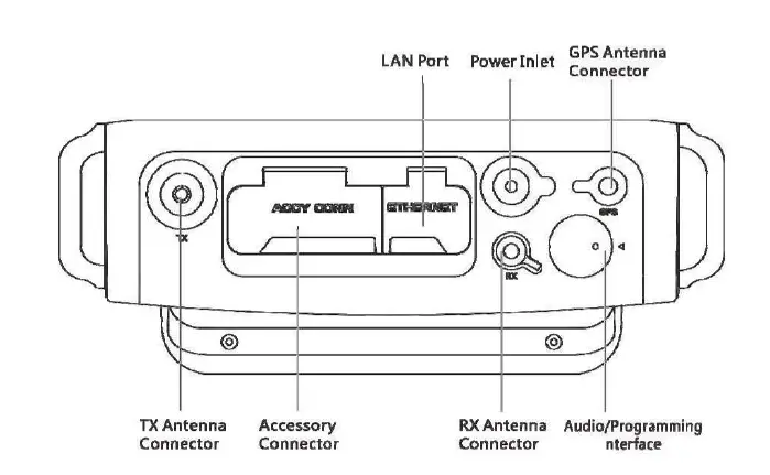
Display Panel 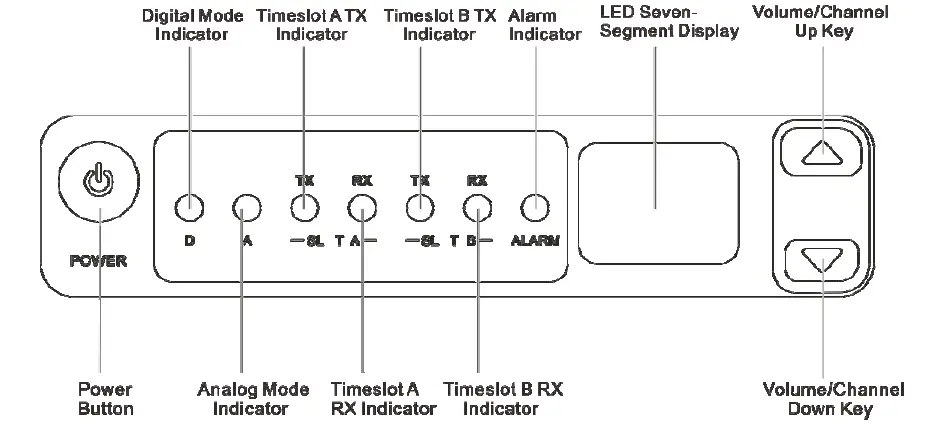
Basic Operations
Turning the Product On or Off
- Connect the product to the power supply through the power adapter, or attach the battery.
- To turn the product on or off, long-press the Power Button.
NOTE: If the power adapter is disconnected from the power supply and no battery is attached, the product will automatically turn off. Then, when the power adapter is reconnected to the power supply, the product will automatically turn on again.
Switching the Channel
In standby mode, press the Volume/Channel Up key or the Volume/Channel Down key. The current channel code appears on the LED seven-segment display.
Adjusting the Volume
- Long press the Volume/Channel Up key for 5s to switch from channel mode to volume mode.
- Press the Volume/Channel Up key or the Volume/Channel Down key to increase or decrease the volume.
NOTE: If you do not make any operation for more than 5s, of if you long press the Volume/Channel Up key again within 5s, you can press this key to only switch the channel.
Making a Call
Prerequisite
- You have purchased the remote speaker microphone (RSM).
- The TX channel has been preprogrammed to the digital channel or mixed channel by your dealer.
If the mixed channel is preprogrammed, you need to set the channel to digital channel on the product. - The TX contacts have been preprogrammed by your dealer.
Procedure
- Connect the RSM to the product.
- Press and hold the PTT key on the RSM, and then speak.
- Release the PTT key.
If no TX contacts are preprogrammed, when you make a call, the digital mode indicator will flash once rapidly. For more details about the product status, see 3 LED Indicators and 4 LED Seven-Segment Display.
LED Indicators
| Indicator | Status | Description |
| Digital Mode Indicator | Blue | The product is operating in digital mode. |
| Analog Mode Indicator | Orange | The product is operating in analog mode. |
| Alarm Indicator | Red | The product is not working properly, and shows the alarm code on the display. |
|
Timeslot A TX Indicator |
Red | l Analog mode: The product is transmitting. l Digital mode: The product is transmitting on timeslot A. |
|
Timeslot A RX Indicator |
Green | l Analog mode: The product is receiving. l Digital mode: The product is receiving on timeslot A. |
| Timeslot B TX Indicator | Red | In the digital mode, the product is transmitting on timeslot B. |
| Timeslot B RX Indicator | Green | In the digital mode, the product is receiving on timeslot B. |
LED Seven-Segment Display
Alarm Code
| Alarm Code | Alarm Type | Alarm Code | Alarm Type |
| E1 | Battery mismatch alarm | E9 | Slave unregistered alarm |
| E2 | Low battery alarm | EE | Repeater disabled alarm |
| E3 | Under-voltage alarm | Eb | Forward power alarm |
| E4 | TX unlocked alarm | EH | Over-voltage alarm |
| E5 | RX unlocked alarm | H3 | Network IP conflict alarm |
| E6 | High temperature alarm | H5 | Invalid IP address alarm |
| E7 | Voltage standing wave ratio (VSWR) alarm | H6 | Out of contact alarm |
| E8 | Off-lease alarm | bP | Standby alarm |
Channel Code
| Channel Code | Description |
| N | Indicates the current channel, such as 1, 2, 3, or more. |
FCC Statement
This equipment has been tested and found to comply with the limits for a Class B digital device, pursuant to part 15 of FCC Rules. These limits are designed to provide reasonable protection against harmful interference in a residential installation. This equipment generates and can radiate radio frequency energy. If not installed and used in accordance with the instructions, it may cause harmful interference to radio communications. However, there is no guarantee that interference will not occur in a particular installation. Verification of harmful interference by this equipment to radio or television reception can be determined by turning it off and then on. The user is encouraged to try to correct the interference by one or more of the following measures:
- Reorient or relocate the receiving antenna. Increase the separation between the equipment and receiver.
- Connect the equipment into an outlet on a different circuit to that of the receiver’s outlet.
- Consult the dealer or an experienced radio/TV technician for help.
Operation is subject to the following two conditions:
- This device may not cause harmful interference.
- This device must accept any interference received, including interference that may cause undesired operation.
Note: Any changes or modifications to this unit not expressly approved by the party responsible for compliance could void the user’s authority to operate the equipment.
Operational Instructions and Training Guidelines
To ensure optimal performance and compliance with the occupational/controlled environment RF energy exposure limits in the above standards and guidelines, users should transmit not more than 50% of the time and always adhere to the following procedures:
- Antenna gain must not exceed 10 dBi
- The antenna must be installed complying with the requirements of the manufacturer or supplier, and it must be at least 86cm away from the human body.
FCC Radiation Exposure Statement:
This equipment complies with FCC radiation exposure limits set forth for an occupational/controlled environment.
This transmitter must not be co‐located or operating in conjunction with any other antenna or transmitter. This equipment should be installed and operated with a minimum distance cm between the radiator & your body.
ISEDC Radiation Exposure Statement:
This equipment complies with ISEDC RF radiation exposure limits set forth for an occupational/controlled environment. This transmitter must not be co-located or operating in conjunction with any other antenna or transmitter. This equipment should be installed and operated with a minimum distance 86 cm between the radiator& your body.


