![]() HR106XU1S Digital Repeater
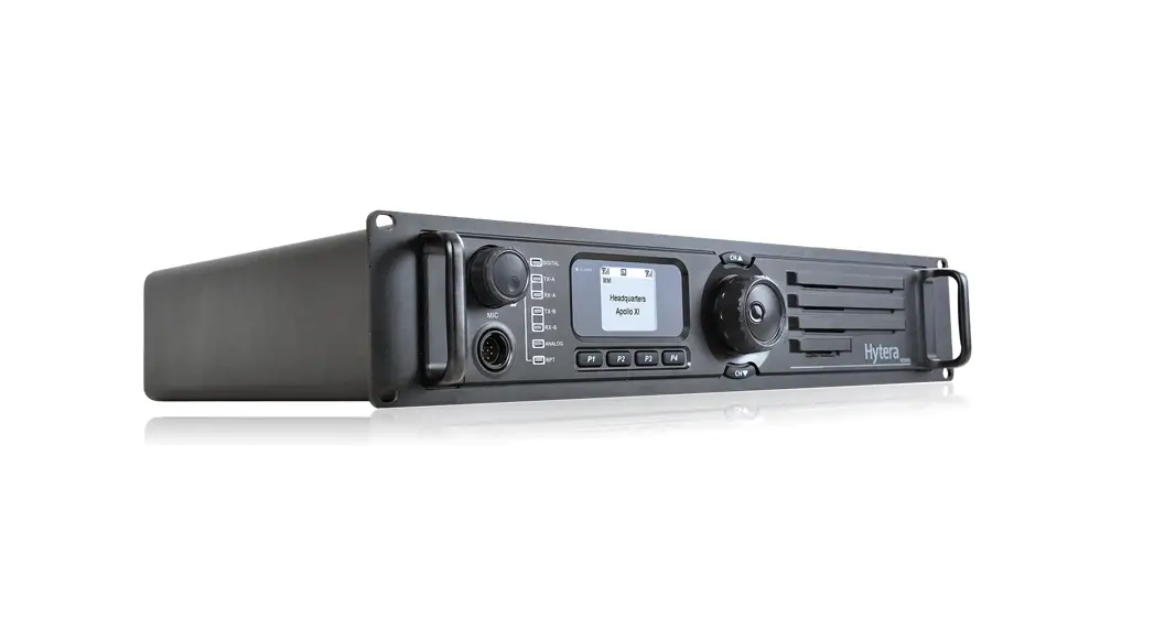
HR106XU1S Digital Repeater
User Guide

Product Overview
Front Panel
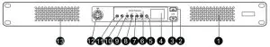
No. | Part Name | No. | Part Name |
| 1 | Air !Met for PA | 8 | Timeslot A RX Indicator |
| 2 | Volume/Channel + Key | 9 | Timeslot A TX Indicator |
| 3 | Volume/Channel – Key | 10 | Analog Mode Indicator |
| 4 | Seven-segment Display | 11 | Digital Mode Indicator |
| 5 | Alarm Indicator | 12 | Audio/Programming Interface |
| 6 | Timeslot B RX Indicator | 13 | Air Inlet for Power Supply |
| 7 | Timeslot B TX Indicator | / | / |
Rear panel
Basic version
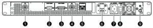
| No | Part Name | No. | Part Name |
| I | TX Antenna Connector | 6 | DC Power Inlet |
| 2 | Monitor/Tuning Interface | 7 | AC Power Inlet |
| 3 | Accessory Connector | 8 | AC Power Switch |
| 4 | RX Antenna Connector | 9 | Ground Screw |
| 5 | Ethernet Interface | / | / |
Advanced version
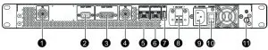
| No. | Part Name | No. | Part Name |
| 1 | TX Antenna Connector | 7 | USB Connector |
| 2 | Monitor/Tuning Interface | 8 | DC Power Inlet |
| 3 | Accessory Connector | 9 | AC Power Inlet |
| 4 | RX Antenna Connector | 10 | AC Power Switch |
| 5 | Ethernet Interface 1 | 11 | Ground Screw |
| 6 | Ethernet Interface 2 | / | / |
![]() NOTE
NOTE
In routing mode, Ethernet interface 1 and Ethernet interface 2 must serve as LAN port and WAN port respectively.
Internal Parts
Basic version
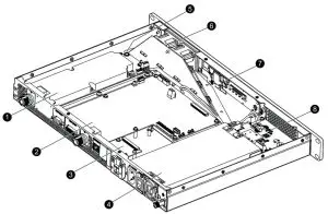
| No. | Part Name | No. | Part Name |
| 1 | PA Module | 5 | Wind Scooper |
| 2 | Main Board | 6 | Fan |
| 3 | Network Board | 7 | Control Panel |
| 4 | Power Supply Module | 8 | Float Charging Board |
Advanced version
| No. | Part Name | No. | Part Name |
| 1 | PA Module | 5 | Wind Scooper |
| 2 | Main Board | 6 | Fan |
| 3 | Coprocessor | 7 | Control Panel |
| 4 | Power Supply Module | 8 | Float Charging Board |
Installation
To ensure optimum performance and reliability of the repeater, read the following instructions carefully.
Installation Requirements
Environmental Conditions
The repeater must be installed in a dry and well-ventilated place. The operating temperature ranges from —30°C to +60°C, and the relative humidity is 95%.
Installation Site
The repeater can be installed in a rack, bracket, and cabinet, or on a desk.
![]() NOTE
NOTE
For more information, refer to the Safety Information Booklet.
Pre-installation Tasks
Preparing the Tools
- T-10 Torx screwdriver
- Spanner
- Anti-static gloves
- Multimeter
Checking the Power Supply
Before you install the repeater, make sure that the power supply meets the following requirements:
- DC power voltage: 13.6±15% V
- AC Power voltage: 120V
Installation Procedure
To install the repeater, do as follows:
- Wear anti-static gloves.
- Place the repeater in a proper location.
 NOTE
NOTE
If the repeater is installed in outdoor environments with frequent thunderstorms, such as the top of mountains or buildings, you must install an external lightning protection module (optional) on the network interface. - Connect the antenna, feed line, power cord and ground cable to the repeater.
NOTE
•You must purchase the antenna and feed lines separately.
•You must prepare a ground cable.
- Ground the repeater through the ground screw located
Post-installation Check
To check whether the repeater works properly, do as follows:
- Turn the repeater on.
- Observe the LED indicators and the display in the front panel.
• If the repeater works properly, the power supply indicator on the float charging board glows yellow or blue, and the display shows the current channel.
• If not, the power supply indicator glows red, and the display shows the alarm code.
![]() NOTE
NOTE
For details, see checking the status.
Basic Operations
Turning On or Off the Repeater
- If the repeater is connected to a DC power supply, press the power switch on the DC power supply to turn on or off the repeater.
After turn-on, if the power supply indicator turns red, the repeater goes into locked status. You must switch off the DC power supply for four seconds, and then switch on the power supply again. - If the repeater is connected to an AC power supply, press the AC Power Switch in the rear panel to turn on or off the repeater.
After turn-on, the power supply indicator turns yellow.
Changing the Channel
Press the Volume/Channel + or Volume/Channel — key to change the channel.
The current channel number appears on the display of the repeater.
Adjusting the Volume
- Long press the Volume/Channel + key for five seconds to switch the repeater from channel mode to volume
- Press the Volume/Channel + or Volume/Channel — key to increase or decrease the volume.
If you do not have any operation for greater than five seconds or if you long-press the Volume/Channel + key again within five seconds, the repeater switches to channel mode.
Checking the Status
Repeater
| Indicator | Description | Repeater Status |
| Digital Mode | Blue | The repeater is operating in digital mode. |
| Analog Mode | Yellow | The repeater is operating in analog mode. |
| Alarm | Red | The repeater is not working properly, and the display shows the alarm code. |
| Timeslot A TX | Red | •Analog mode: The repeater is transmitting. •Digital mode: The repeater is transmitting on timeslot A. |
| Timeslot A RX | Green | •Analog mode: The repeater is receiving. •Digital mode: The repeater is receiving on timeslot A. |
| Timeslot B TX | Red | Digital mode: The repeater is transmitting on timeslot B. |
| Timeslot B RX | Green | Digital mode: The repeater is receiving on timeslot B. |
Network Interface
| Indicator | Description | Repeater Status | |
| Ethernet Interface | LED 1 | Flashing | The network interface card is transmitting data. |
| LED 2 | Glowing | The data transmission rate is 1000 Mbps/100 Mbps. | |
| Off | The data transmission rate is 10 Mbps. | ||
Power supply
| Indicator | Description | Repeater Status |
| Power Supply (Visible through the Air Inlet for Power Supply) | Yellow | The repeater is supplied by AC power. |
| Blue | The repeater is supplied by a DC power. | |
| Red | The repeater cannot be turned on. |
For details on more features and operations, please visit our website at: http://www.hytera.com, or scan the QR code to download the User Manual.
 https://www.hytera.com/ziyuan?siteId=1&id=75340&type=2
FCC Statement
This equipment has been tested and found to comply with the limits for a Class B digital device, pursuant to part 15 of FCC Rules. These limits are designed to provide reasonable protection against harmful interference in a residential installation. This equipment generates and can radiate radio frequency energy. If not installed and used in accordance with the instructions, it may cause harmful interference to radio communications. However, there is no guarantee that interference will not occur in a particular installation. Verification of harmful interference by this equipment to radio or television reception can be determined by turning it off and then on. The user is encouraged to try to correct the interference by one or more of the following measures:
- Reorient or relocate the receiving antenna. Increase the separation between the equipment and
- Connect the equipment into an outlet on a different circuit to that of the receiver’s outlet.
- Consult the dealer or an experienced radio/TV technician for help.
Operation is subject to the following two conditions:
- This device may not cause harmful interference.
- This device must accept any interference received, including interference that may cause undesired operation.
Note: Any changes or modifications to this unit not expressly approved by the party responsible for compliance could void the user’s authority to operate the equipment.
Operational Instructions and Training Guidelines
To ensure optimal performance and compliance with the occupational/controlled environment RF energy exposure limits in the above standards and guidelines, users should transmit not more than 50% of the time and always adhere to the following procedures:
- Antenna gain must not exceed 5dBi.
- The antenna must be installed complying with the requirements of the manufacturer or supplier, and it must be at least 63cm away from the human body.
FCC Radiation Exposure Statement:
This equipment complies with FCC radiation exposure limits set forth for an occupational/controlled environment.
This transmitter must not be co-located or operating in conjunction with any other antenna or transmitter. This equipment should be installed and operated with a minimum distance of 63cm between the radiator & your body.
ISEDC Radiation Exposure Statement:
This equipment complies with ISEDC RF radiation exposure limits set forth for an occupational/controlled environment. This transmitter must not be co-located or operating in conjunction with any other antenna or transmitter. This equipment should be installed and operated with a minimum distance 63cm between the radiator& your body.
IC exposition aux radiations:
Cet equipement est conforme avec ISEDC les limiter d’exposition aux rayonnements definies pour un environnement professionnel/controle.Cet emetteur ne doit pas etre co-localises ou fonctionner en conjonction avec une autre antenne ou emetteur.Cet equipement doit etre installe et utiliseavec une distance minimale de 63cm entre leradiateur & votre corps.
![]() is the trademark or registered trademark of Hytera Communications Corporation Limited.
is the trademark or registered trademark of Hytera Communications Corporation Limited.
© 2020 Hytera Communications Corporation Limited. All Rights Reserved.
Address: Hytera Tower, Hi-Tech Industrial Park North,9108#Beihuan Road,
Nanshan District, Shenzhen, People’s Republic of China
Postcode:518057
http://www.hytera.com