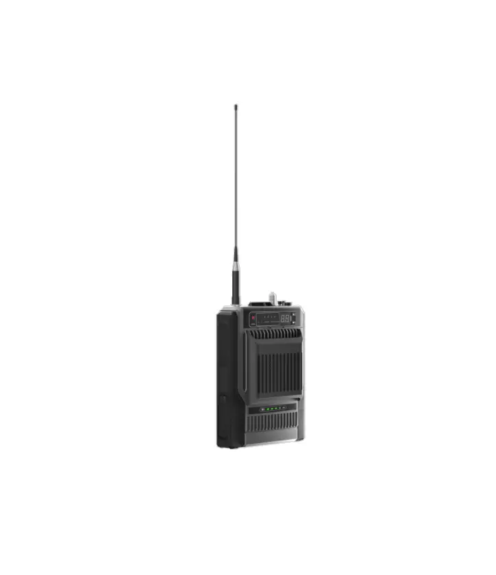
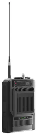
Hytera HR65X Digital Repeater
Preface
Welcome to the world of Hytera and thank you for purchasing this product. This manual includes a description of the functions and step-by-step procedures for use.
To avoid bodily injury or property loss caused by incorrect operation, please carefully read the Safety Information Booklet before use.
This manual is applicable to the following product:
HR65X Digital Repeater (X may represent 2, 5, 6, 8, or 9)
Copyright Information
Hytera is the trademark or registered trademark of Hytera Communications Corporation Limited (the Company) in the People’s Republic of China (PRC) and/or other countries or areas. The Company retains the ownership of its trademarks and product names. All other trademarks and/or product names that may be used in this manual are properties of their respective owners.
The product described in this manual may include the Company’s computer programs stored in memory or other media.
Laws in PRC and/or other countries or areas protect the exclusive rights of the Company with respect to its computer programs. The purchase of this product shall not be deemed to grant, either directly or by implication, any rights to the purchaser regarding the Company’s computer programs. The Company’s computer programs may not be copied, modified, distributed, decompiled, or reverse-engineered in any manner without the prior written consent of the Company.
Disclaimer
The Company endeavors to achieve the accuracy and completeness of this manual, but no warranty of accuracy or reliability is given. All the specifications and designs are subject to change without notice due to continuous technological development. No part of this manual may be copied, modified, translated, or distributed in any manner without the prior written consent of the Company.
We do not guarantee, for any particular purpose, the accuracy, validity, timeliness, legitimacy or completeness of the third-party products and contents involved in this manual.
If you have any suggestions or would like to receive more information, please visit our website at: https://www.hytera.com.
FCC Statement
This equipment has been tested and found to comply with the limits for a Class B digital device, pursuant to part 15 of FCC Rules. These limits are designed to provide reasonable protection against harmful interference in a residential installation. This equipment generates and can radiate radio frequency energy. If not installed and used in accordance with the instructions, it may cause harmful interference to radio communications. However, there is no guarantee that interference will not occur in a particular installation. Verification of harmful interference by this equipment to radio or television reception can be determined by turning it off and then on. The user is encouraged to try to correct the interference by one or more of the following measures:
- Reorient or relocate the receiving antenna. Increase the separation between the equipment and receiver.
- Connect the equipment into an outlet on a different circuit to that of the receiver’s outlet.
- Consult the dealer or an experienced radio/TV technician for help.
Operation is subject to the following two conditions: - This device may not cause harmful interference.
- This device must accept any interference received, including interference that may cause undesired operation
Note: Any changes or modifications to this unit not expressly approved by the party responsible for compliance could void the user’s authority to operate the equipment.
Operational Instructions and Training Guidelines
To ensure optimal performance and compliance with the occupational/controlled environment RF energy exposure limits in the above standards and guidelines, users should transmit not more than 50% of the time and always adhere to the following procedures:
- Antenna gain must not exceed 10 dBi.
- The antenna must be installed complying with the requirements of manufacturer or supplier, and it must be at least 86 cm away from human body.
FCC Radiation Exposure Statement
This equipment complies with FCC radiation exposure limits set forth for an occupational/controlled environment.
This transmitter must not be co‐located or operating in conjunction with any other antenna or transmitter. This equipment should be installed and operated with a minimum distance of 86 cm between the radiator and your body.
ISEDC Radiation Exposure Statement
This equipment complies with ISEDC RF radiation exposure limits set forth for an occupational/controlled environment. This transmitter must not be co-located or operating in conjunction with any other antenna or transmitter.
This equipment should be installed and operated with a minimum distance of 86 cm between the radiator and your body.
EU Regulatory Conformance
As certified by the qualified laboratory, the product is in compliance with the essential requirements and other relevant provisions of 2014/53/EU.
The maximum antenna gain is 10 dBi. The minimum safety distance is 103 cm.
Please note that the above information is applicable to EU countries only.
Specifications
Parameter | Description |
Frequency |
|
Output Power |
|
Documentation Information
Documentation Conventions
Instruction Conventions
| Icon | Description |
| Indicates information that can help you make better use of your product. |
| Indicates references that can further describe the related topics. |
| Indicates situations that could cause data loss or equipment damage. |
| Indicates situations that could cause minor personal injury. |
| Indicates situations that could cause major personal injury or even death. |
Notation Conventions
Item | Description | Example |
Boldface | Denotes menus, tabs, parameter names, window names, dialogue names, and hardware buttons. | To save the configuration, click Apply. |
| The Log Level Settings dialogue box appears. | ||
| Press the PTT key. | ||
” “ | Denotes messages, directories, file names, folder names, and parameter values. | The screen displays “Invalid Battery!”. |
| Open “PSS.exe”. | ||
| Go to “D:/opt/local”. | ||
| In the Port text box, enter “22”. | ||
> | Directs you to access a multi-level menu. | Go to File > New. |
Italic | Denotes document titles. | For details about using the DWS, refer to Dispatch Workstation User Guide. |
Courier New | Denotes commands and their execution results. | To set the IP address, run the following command: vos-cmd – m name IP |
Revision History
Document Version | Product Version | Release Date | Description |
| 00 | V00 | July 2022 | Initial release. |
Packing List
Unpack carefully and check that you have received the following items. If any item is missing or damaged, contact your dealer
Item | Quantity (PCS) | Item | Quantity (PCS) |
Repeater | 1 | Documentation Kit | 1 |
| Power Cord | 1 | / | / |
 NOTE
NOTE
Figures in this document are for reference only.
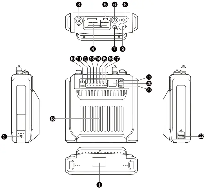
Product Layout
No. | Part Name | No. | Part Name |
| 1 | Bottom cover | 12 | Analog mode indicator |
2 | USB port | 13 | Timeslot A TX indicator |
| 3 | TX/Duplexer antenna connector (UHF female) | 14 | Timeslot A RX indicator |
4 | Accessory connector | 15 | Timeslot B TX indicator |
| 5 | Ethernet port | 16 | Timeslot B RX indicator |
6 | Power inlet | 17 | Alarm indicator |
| 7 | RX antenna connector (SMA female) | 18 | Fan |
8 | GNSS antenna connector (SMA female) | 19 | Volume/Channel up key |
| 9 | Aviation port | 20 | Seven-segment LED |
10 | On-Off key | 21 | Volume/Channel down key |
| 11 | Digital mode indicator | 22 | Battery latch |
NOTE
Except that the low-power HR65X features no fan but the high-power HR65X features one, the other hardware of the two types is the same.
Precaution
Before installation and use, read the following instructions carefully.
- Install the repeater in a dry and well-ventilated place.
- Use the repeater in an environment where the temperature is between –30°C and +60°C and the relative humidity is equal to or lower than 95%.
- Ensure that the operating voltage is 12–16.8 V DC.
NOTE
For more information, refer to the Safety Information Booklet.
Installation
You can place the repeater on the desk, or install the repeater on the wall.
Tools
- Electric drill
- Screwdriver
- Wrench
- Anti-static gloves
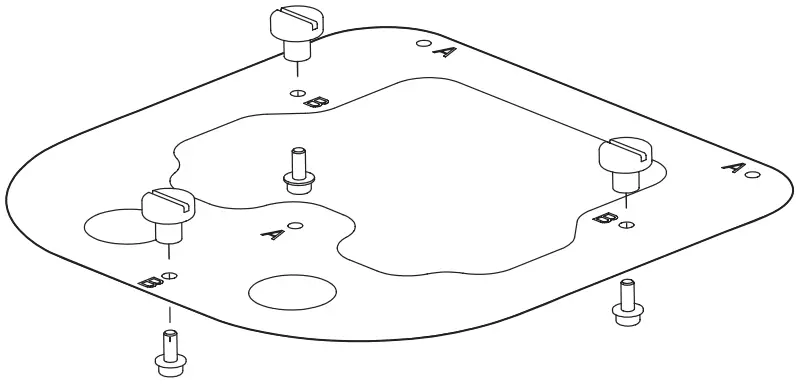
Procedure
- Install the three pegs onto the fixing plate with three M3 screws at holes marked with “B”.

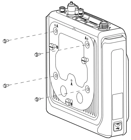
- Fix the fixing plate to the back of the repeater with four M4 screws.

- Install the repeater on the wall.
NOTE
Before installation, make sure the weight of the repeater is within the load bearing capacity of the wall.
a. Hold the bracket horizontally to a proper position on the wall, and then mark the locations of the three holes (Φ = 8 mm, h = 60 mm) as anchor points.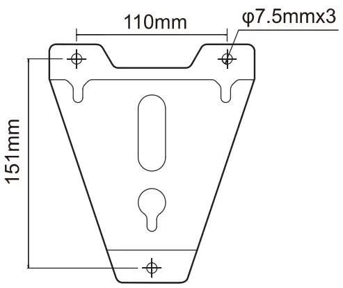
b. Drill three holes at the anchor points with an electric drill.
c. Fix the bracket onto the wall with three M6 expansion bolts.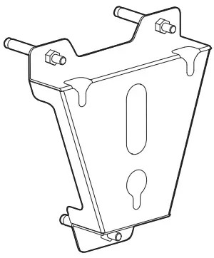
d. Dock the three holes on the bracket with the three pegs on the back of the repeater.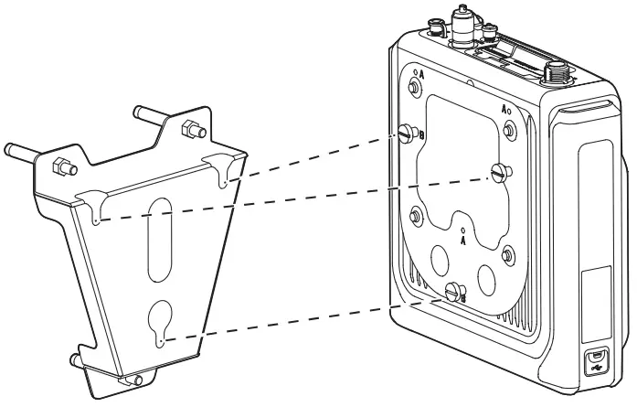
Basic Operation
Turning On or Off the Repeater
- Automatically Turn On
When connected to external power supply, the repeater automatically turns on. - Manually Turn On or Off
When connected to external power supply, long press the On-Off key to turn on or off the repeater.
Switching the Channel
In the standby mode, press the Volume/Channel Up key or the Volume/Channel Down key.
The seven-segment LED displays the current channel number.
Adjusting the Volume
- To switch the Volume/Channel Up key to the volume mode, press the key for five seconds.
 NOTE
NOTE
If you do not have any operation or you long press the Volume/Channel Up key within five seconds, the key will switch to the channel mode. - Press the Volume/Channel Up key to increase or the Volume/Channel Down key to decrease the volume.
(Optional) Transmitting
- Connect the remote speaker microphone (RSM) to the repeater.
- Press the push-to-talk (PTT) key on the RSM.
You can learn about the repeater status from LED indicators. For details, see 5 错误!书签自引用无效。.
NOTE
- The RSM is optional.
- Use the RSM specified by Hytera.
- PTT TX Channel Type and TX Contact Name are configured by the dealer
- The repeater gives no indication or response if it detects no TX contact name on the current channel (digital or hybrid) after PTT is pressed.
Status Indication
| Indicator | Status | Description |
| Digital mode indicator | Glows blue | The repeater is in the digital mode. |
| Analog mode indicator | Glows orange | The repeater is in the analog mode. |
| Alarm indicator | Glows red | An exception occurs (The seven-segment LED displays the corresponding alarm code). |
| Timeslot A TX indicator | Glows red | Analog mode: transmitting Digital mode: Timeslot A is transmitting. |
| Timeslot A RX indicator | Glows green | Analog mode: receiving Digital mode: Timeslot A is receiving. |
| Timeslot B TX indicator | Glows red | Timeslot B is transmitting in the digital mode. |
| Timeslot B RX indicator | Glows green | Timeslot B is receiving in the digital mode. |
Seven-Segment LED
Alarm Code
Alarm Code | Description | Alarm Code | Description |
E3 | External power under-voltage alarm | EE | Repeater disabled alarm |
E4 | TX unlocked alarm | Eb | Low forward power alarm |
E5 | RX unlocked alarm | EH | External power over-voltage alarm |
E6 | Over-temperature alarm | H3 | Network IP conflict alarm |
E7 | Voltage standing wave ratio (VSWR) alarm | H5 | Invalid network IP alarm |
E8 | Off-lease alarm | bP | Backup alarm |
E9 | Slave unregistered alarm | / | / |
Channel Code
Channel Code | Description |
N | Indicates the current channel number, for example, 1, 2, 3, or more. |
Alarm Information
With the Alarm feature enabled by your dealer, the repeater automatically triggers an alarm if any exception occurs.
When the alarm is active, the LED displays the corresponding alarm code and the alarm indicator glows red.
The following table describes alarms in detail.
Alarm Code | Alarm Name | Description | ||||||||||||
E3 | External power under-voltage alarm | The repeater fails to work. In this case, if the Repeater Backup feature is enabled on the CPS, the repeater starts a backup. | ||||||||||||
E4 | TX unlocked alarm | The repeater fails to work. In this case, if the Repeater Backup feature is enabled on the CPS, the repeater starts a backup. | ||||||||||||
E5 | RX unlocked alarm | The repeater fails to work. In this case, if the Repeater Backup feature is enabled on the CPS, the repeater starts a backup. | ||||||||||||
E6 | PA ver- temperature alarm | The repeater fails to work. In this case, if the Repeater Backup feature is enabled on the CPS, the repeater starts a backup. | ||||||||||||
E7 | Voltage standing wave ratio (VSWR) alarm | The repeater automatically works at lower TX power. | ||||||||||||
E8 | Off-lease alarm | The repeater fails to work. | ||||||||||||
E9 | Slave alarm | unregistered | The repeater network. | cannot | repeat | the | signal | or | data | in | the | IP | multisite | connect |
EE | Repeater disabled alarm | The repeater fails to work. | ||||||||||||
Eb | Low forward power alarm | The repeater stops transmission when the TX power is 0 W. | ||||||||||||
| EH | External power over-voltage alarm | The repeater fails to work. In this case, if the Repeater Backup feature is enabled on the CPS, the repeater starts a backup. | ||||||||||||
H3 | Network IP conflict alarm | Network services of the repeater are unavailable. | ||||||||||||
H5 | Invalid network IP alarm | Network services of the repeater are unavailable. | ||||||||||||
bP | Backup alarm | The repeater works as a standby repeater. | ||||||||||||
External Power Under-voltage or Over-voltage Alarm
Description
When the repeater detects that the voltage of the external power supply is out of range, the alarm indicator glows red and the LED displays “E3” for under-voltage alarm or “EH” for over-voltage alarm. In this case, the repeater fails to work.
Solution
- Check whether the power adapter is damaged.
• If yes, replace the power adapter.
• If no, go to step 2. - Check whether the input voltage of external power supply is beyond the repeater’s operating voltage range with a voltmeter.
• If yes, replace the power adapter.
• If no, contact your dealer for technical support
TX/RX Unlocked Alarm
Description
When the TX/RX phase-locked loop unlocks, the alarm indicator glows red and the LED displays “E4” for TX unlock or “E5” for RX unlock.
In this case, the repeater automatically fails to provide certain features.
Solution
Contact your dealer for technical support.
PA Over-temperature Alarm
Description
When the repeater detects that the internal temperature of the PA module exceeds the upper threshold, the alarm indicator glows red and the LED displays “E6”.
In this case, the repeater stops transmission.
Solution![]() CAUTION
CAUTION
When the repeater triggers this alarm, to avoid risk of burns, DO NOT touch the repeater.
- Use the digital thermometer with thermocouple to check whether the surface temperature of the PA module is over 90°C.
• If yes, go to step 2.
• If no, go to step 3. - Check whether the ambient temperature and ventilation conditions of the repeater meet the installation requirements. NOTE
For the high-power HR65X, besides the temperature and ventilation conditions, check whether the fan works and the heat exhaust duct is clean.
• If yes, go to step 3.
• If no, take appropriate measures (for example, install more heat sink devices, replace fans, or clean the duct)
to reduce the ambient temperature and improve ventilation. - Check whether the TX power is too high and the temperature of heat sink is rising too fast.
• If yes, go to step 4.
• If no, contact your local dealer for technical support. - Check whether the RF adapter cable, antenna, or feed line is properly connected.
• If yes, contact your dealer for technical support.
• If no, re-connect or replace the cable, antenna, or feed line.
VSWR Alarm
Description
When the repeater detects the VSWR at the TX antenna of the PA module exceeds the upper threshold, the alarm indicator glows red and the LED displays “E7 In this case, the repeater automatically works at lower TX power.
Solution
- Check whether the TX frequency is within the frequency range of the antenna.
• If yes, go to step 2.
• If no, contact your dealer to replace the antenna. - Check whether the RF adapter cable, antenna, or feed line is properly connected.
• If yes, contact your dealer for technical help.
• If no, re-connect or replace the cable, antenna, or feed line.
Off-lease Alarm
Description
When the rental time of the repeater expires, the alarm indicator glows red and the LED displays “E8”. In this case, the repeater fails to work.
Solution
Contact your dealer to extend the rental lease.
Slave Unregistered Alarm
Description
In the IP multi-site connect network, if the repeater works as a slave one and fails to send a registration request to the master repeater, the alarm indicator glows red and the LED displays “E9”.
In this case, the repeater cannot repeat the signal or data in the IP multi-site connect network.
Solution
Check and modify the network configuration.
Repeater Disabled Alarm
Description
With the Repeater Disable feature enabled by your dealer, when the repeater detects the active level, the alarm indicator glows red and the LED displays “EE”.
In this case, the repeater fails to work.
NOTE
- When the repeater detects the invalid level, the repeater restarts and returns to the normal state.
- The repeater restarts every time the level changes.
Solution
Contact your dealer for technical support.
Low Forward Power Alarm
Description
When the repeater detects that the TX power is below the preset value of forward power, the alarm indicator glows red and the LED displays “Eb”.
When the TX power is 0 W, the repeater stops transmission.
Solution
Check whether the RF adapter cable, antenna, or feed line is properly connected.
- If yes, contact your dealer for technical support.
- If no, re-connect or replace the cable, antenna, or feed line.
Network IP Conflict Alarm
Description
When the IP address of the repeater conflicts with that of other devices in the same network segment, the alarm indicator glows red and the LED displays “H3”.
In this case, network services of the repeater are unavailable.
Solution
Check and modify the network configuration.
Invalid Network IP Alarm
Description
When the repeater fails to acquire valid IP address with DHCP, the alarm indicator glows red and the LED displays “H5”.
In this case, network services of the repeater are unavailable.
Solution
Check whether the network cable is properly connected.
- If yes, check whether the DHCP server is deployed.
- If no, reconnect the network cable.
Troubleshooting
| Phenomena | Analysis | Solution | ||||
| The repeater cannot be turned on. | The power cord may be disconnected or get loose. | Re-connect the power cord. | ||||
| The fuse in the DC power cord may be damaged. | Replace the fuse. | |||||
| The repeater cannot communicate with a radio. | The TX/RX frequencies or the color code of the repeater may be inconsistent with that of the radio. | Reset the frequencies or color code. | ||||
| The continuous tone controlled squelch system (CTCSS)/continuous digital controlled squelch system (CDCSS) of the repeater may be inconsistent with that of the radio. | Reset the CTCSS or CDCSS. | |||||
| The repeater may suffer severe interference. | Keep the interference frequencies. | repeater source, | away or | from change | the the | |
| The radio may be out of the communication coverage of the repeater. | Move the radio towards the communication coverage of the repeater. | |||||
| The antenna is disconnected. | Reconnect the antenna. | |||||
| Within the communication coverage of the repeater, the radiosuffers short communication distance and poor audio quality. | The cable may be damaged. | Repair the cable, or replace the cable if necessary. | ||||
| The antenna may get loose or be disconnected. | Re-connect the antenna properly, or replace the antenna if necessary. | |||||
If the above solutions cannot fix your problems, or you may have some other queries, contact the Company or your dealer for more technical support.
Care and Cleaning
To guarantee optimum performance as well as a long service life of the product, follow the tips below.
Product Care
- Do not pierce or scrape the product.
- Keep the product away from substances that can corrode the circuitry.
Product Cleaning
![]() CAUTION
CAUTION
Turn off the product before cleaning
- Clean up the dust and fine particles on the product surface with a clean and dry lint free cloth or a brush regularly.
- Use neutral cleanser and a non-woven fabric with neutral cleanser to clean the keys, knobs, display, and connectors after long-time use. Do not use chemical preparations such as stain removers, alcohol, sprays or oil preparations, so as to avoid surface case damage.
- Make sure the product is completely dry before use.
Optional Accessories
![]() CAUTION
CAUTION
Use the accessories specified by the Company only. Otherwise, we will not be liable for any loss or damage arising out of use of unauthorized accessories.
Contact your dealer for the optional accessories used with the product.
Abbreviations
Abbreviation | Full Name |
C | |
| CDCSS | Continuous Digital Controlled Squelch System |
CTCSS | Continuous Tone Controlled Squelch System |
D | |
DHCP | Dynamic Host Configuration Protocol |
G | |
GPIO | General Purpose Input/Output |
L | |
LED | Light-Emitting Diode |
| P | |
PA | Power Amplifier |
V | |
VSWR | Voltage Standing Wave Ratio |
Customer Support
is the trademark or registered trademark of Hytera Communications Corporation Limited.
© 2022 Hytera Communications Corporation Limited. All Rights Reserved.
Address: Hytera Tower, Hi-Tech Industrial Park North, 9108# Beihuan Road, Nanshan District, Shenzhen, People’s Republic of China Postcode: 518057
https://www.hytera.com