Abell Industries R 80N Digital Repeater
To user
Thanks
Digital repeater (is briefly referred to as repeater below), use the high-performance radio frequency module, Control panel, Power supply module and Built-in duplexer (Optional), designed as 50w professional repeater.Repeater use the modular design, with high performance and easy to maintain, convenient to update and the interface opening features. Repeater’s main functions are wireless transfer, support local PTT calling and support expanding function, is convenient for users to add other communication functions, which will bring a lot of convenience for your work and life. Repeater use the most advanced and superb technology hope our quality will satisfy you.
User instructions
- Would you please read this manual carefully before using this product, so that you can more easily handle the operation of this machine? When you use this product, we think that you have read the instructions already.
- Please carefully keep this instruction for future reference.
- In order to safeguard your legitimate rights and interests of you, so please seriously truthfully fill in the user’s warranty Card ” when buying our products, and ask for the purchase vouchers.
- fill in the user’s warranty Card ” when buying our products, and ask for the purchase vouchers. changing the soft specifications without prior notice to at any time in this manual.This manual mentioned product specifications and information is only for reference.
Safety Precautions
For the safety and effectiveness of your operation, please read the bellow information carefully.
- High voltage and high temperature, be careful for electric shock and burn
- Maintenance work must be professional and technical, don’t dismount.
- Setting and install must be approved of the radio administrative department.
- Repeater has a ground terminal, which should be carefully ground for the safety and performance of the machine.
- The installation of the antenna must be a lightning protection measure, otherwise may cause seriously lost.
- Please use the qualified antenna, anti-thunder, feeder, power divider to make sure the correct of installation
OOBA
Please be careful when open the packing box,confirm whether has goods inside of the box, if you find something miss or been damage, please contact dealer.
| Item | No. |
| Repeater | 1 |
| AC power supply line | 1 |
| USB data line | 1 |
| Microphone | 1 |
| Coaxial cable (for duplexer) | 1 |
| User manual | 1 |
| Warranty Card | 1 |
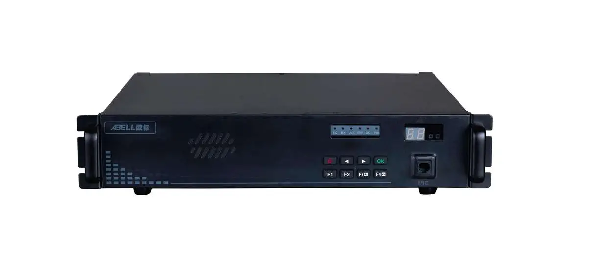
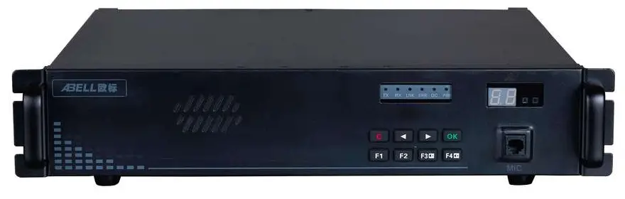
Product Introduction
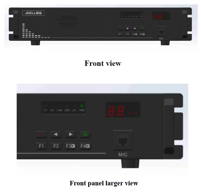
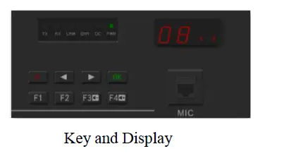
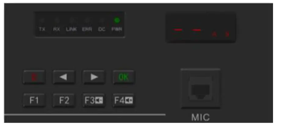
Front panel introduction
| Indicator | Color | Functional description |
| TX | green | Always on, the repeater is transmitting signals |
| RX | green | Always on, the repeater is receiving signals |
| LNK | green | Always on, the link is successful |
| ERROR | red | On or flashes, error occured |
| DC | green | Always on, DC power supply equipment |
| POWER | green | TS B transmit |
| A、B | green | Digital time slot one receive signal, A light on. Digital |
| time slot two, B light on. Analog doesn’t light. |
Digital tube (two bits) instruction
Including two bits eight segments digital tube, the function as below:
- Instruct current working channel number during the working condition.
- Use to display current menu option or some function parameter figures during key operation
- Display current error code when the repeater appear warning.
Front panel board MIC interface
Front panel board MIC interface use to internet microphone, local PTT can be use as talking or use as base station to call. Key function detailed description
| Button | Name | Menu guide function | Parameter editor function |
| C | 1. short press back to up menu or root menu 2. long press back to standby mode and lock the keyboard | Clear or cancel current parameter value | |
| Left | 1. Up level menu 2. Shortcut menu: decrease channel | Value decrease | |
| Right | 1. Next level menu 2. Shortcut menu, increase channel | Value increase | |
| Ok | Enter next level menu | Confirm and save current parameter value | |
| F1 | Function key 1 (software defines) | Figure 1 | |
| F2 | Function key 2 (software defines) | Figure 2 | |
| F3/v_ | 1. Function key 3 (software defines) 2. Shortcuts menu: volume down | Figure 3 |
| F4/v+ | 1. Function key 4 (software defines) 2. Shortcuts menu: volume up | Figure 4 |
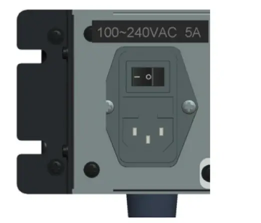
Rear panel port introduction
| Port name | Function declaration |
| USB | Connect with PC,use ain programming、software update。 |
| EXT-I/O | Outside expand interface, including the signal connected with outside and control the Pin, use as specific expanding function. Outside look structure define the interface. |
| RJ11 | Connect with PSTN telephone network or PABX internal telephone network, use as expanding interworking call with telephone network. |
| ANT/TX | Connect with antenna when duplexer installed, connect with transmit antenna when duplexer uninstalled。 |
| ANT/RX | connect with transmit antenna when duplexer uninstalled。 |
Rear panel EXT-I/O port definition
| Pin No. | Definition | Function declaration |
| Pin1 | -13v | Power ground |
| Pin2 | IO_CLKX’ | CLKR output signal, LVTTL_3.3V |
| Pin3 | UART3_RX’ | UART3_RX serial port |
| Pin4 | IO_PTTI | PTTR input signal, LVTTL_3.3V |
| Pin5 | SEL0_IN/SEL0_OUT | Expanding IO-0 LVTTL_3.3V |
| Pin6 | DG | Digital |
| Pin7 | AG | Analog |
| Pin8 | EXT IO_UF_OUT | Extend AF output |
| Pin9 | EXT Ext_MIC | Extend MIC input |
| Pin10 | +13v | 12V_OUT 500mA_max |
| Pin11 | IO_DX | DATAR peripheral equipment information |
| Pin12 | IO_FSX | FSR sync output |
| Pin13 | IO_CLKR | CLKR input signal |
| Pin14 | Ext_BOOT0 | Guidance enabled |
| Pin15 | DG | Digital |
| Pin16 | AG | Analog |
| Pin17 | NDET_OUT | Expanding port (output) |
| Pin18 | NDECT_IN | Expanding port (input) |
| Pin19 | UART3_TX | UART3_TX serial port |
| Pin20 | O_PTTO | PTT output |
| Pin21 | IO_DR | DATAR peripheral equipment voice data |
| Pin22 | IO_FSR | FSR signal lock input |
| Pin23 | DG | Digital |
| Pin24 | AG | Analogue |
| Pin25 | RSSI_IN | Extension field intensity level(0~3V)(in) |
| Pin26 | RSSI_OUT | Extension field intensity level(out) |
Repeater operation
turn on/turn off the repeater
Press “power switch to the ”one” direction to turn on, then the speaker will make a sound, the ‘PWR’ indicator turning red, device start working, the system is going to stand by condition.
Audio, data transmit
Repeater receive the upstream RF signal, and automatically control the transmitter (excitation module and power amplifier module) to transfer, which will enhance the received signal to increase communication distance.
Indication of transit
- ‘A’ and ‘B’ indicator turning light when device is working, indicate the signal is digital,TS1 is during communication when ‘A’ turning light,TS2 is during communication when ‘B’ turning light.
- ‘TX’ and ’RX’ indicator turning light or ‘A’ and ‘B’ not turning light, indicate the signal is analog signal.
Panel keyboard and display
Key tone
- Operate to modify working parameter and operate optional menu key, once “beep” informed.
- Operate parameter error and operate invalid, continual short “beep” sound informed.
Programming software operation
- program wire joint Run R-80 program software installation package, then it will automatically install
- Configure the setup parameters Repeater connect with PC through USB programme cable, open up the repeater power supply after the device being normal working condition, run the R-80 software to the interface bellowed:

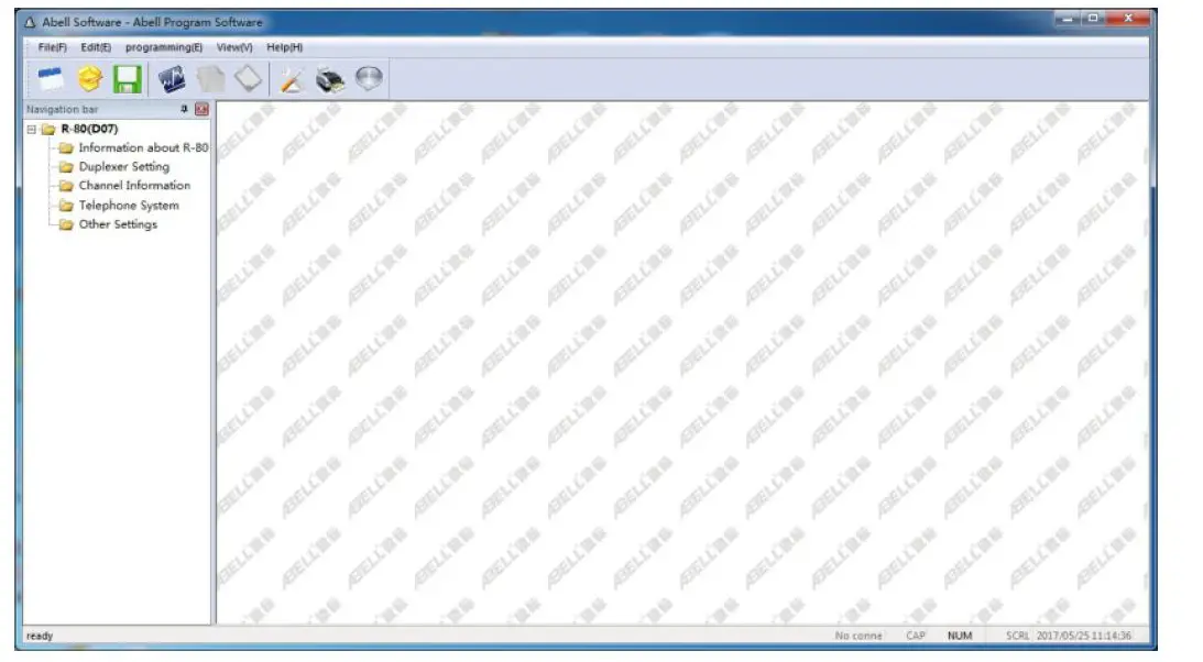
Please refer to “R-80 digital repeater software operation instruction manual” to set up channel, receive and transmit frequency, power, color code and monitor, PTT and so on.
Two-way radio calling
Repeater configuration
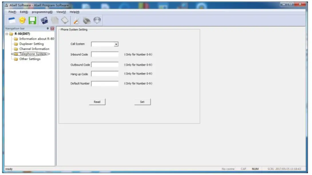
- Find “telephone system” in R-80 program software, configuration as bellowed
 :
:- Calling settings: according need to set whether opening call for or not, default yes: available for call in or call out.
- Call in password: when others call the repeater telephone number, they will need to input this password.
- Call out password: when you need to call others telephone number, you need to input this password.
- Hang up a password: when the calling is over, the repeater need to input this pasword to hang up.
- Embedded password: The repeater default calling out number.
- Only digital channel can use the telephone call function, and choose microphone PTT function, transmit prior option, wireless priority.
- Two-way radios’ configuration
- Handsets must be digital and support PSTN function, we use HYT PD680 as a example. Choose the telephone system under handset digital channel configuration parameter, telephone system one (if you choose none, PSTN can not calling), transmit permission options: allow transmit or color code idle, do not choose channel idle.
- enter menu options: general setting, digital general, basic setting, do not choose Miscellaneous, use single call, back call and all call.
 :
:Answer and make a phone call
- handset make a phone call (for example: call out password is: 222)
- Dial any number: press the PTT button, input :call out password+ * + phone number + #. For example, call 26000000, firstly, press the PTT button, input 222+26000000 on two way radios’ keyboard at the same time, then release PTT button, after a few second, you can see the radios send the phone call from the display, then you can have a call if other side answer.
- Dial embedded number: press PTT buttons on two way radios, input call out password+ #,for example, the embedded number is 075526000000, firstly, press the PTT button, input 222# on keyboard, then release PTT, after a few seconds you can have a call with 075526000000.
- Handsets (repeater) answer the call (the call in password is :111 )If other side use the plane or phone to call the handsets (repeater), after get through you need to input call password+#(111#), then you can have a call.
- Handsets(repeater) hang up the phone, ( the hang up password is 333 etc): When the call is over, if the other side not hang up, the repeater will hang up itself, the operation is : press the PTT, then input: hang up password +# (333#).
Panel operation
Holding state
When the device start to work, the panel enter holding state, and will display current channel number, the picture below is channel number 8.
Menu function
Panel function operation include: channel switching, monitor volume adjustment, monitor switch (P1), transmit power regulation (P2), password changing (P3), the channel switching and the volume adjustment are in shortcut menu, others are general function, operation mode is different, the operation process like below: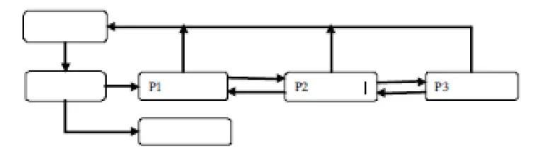 If the device does not open the password lock function, press “OK” button to pass password authentication process.
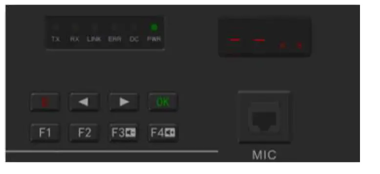
Password authentication
- If the current state is menu lock state, press “OK” or shortcuts function button enter password authentication, the digital tube will display and shining, wait for you to enter password. The password consist of “1” “2” “3” “4” in any random order, six figures, the corresponding button is

- After inputting the password, press , if the password is correct will enter the menu “P1” or performs shortcuts, or will occur warning.
- Press before will remove the password number you input.
- In any menu press the device will enter the password lock up state and holding state.
- Long time (more than 30 seconds) no button been press, the device will enter password lock up state and holding state.
Channel switching
Channel switching function is shortcuts menu function, directly press or to change the current channel, if the menu have password lock, you need the password authentication,channel number will display “01-99”, when you press when you changing to target channel, then press repeater will change to target channel to start work, press to confirm, digital display stop shining, back to holding state, and display the current work channel number.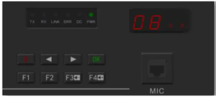
Volume adjustment
Volume adjustment function as shortcut menu function, press or , changing speaker volume, the volume can be U1 to U8 level, U1 is the lowest, U8 is the highest, when you press
or , the digital display will start to shine, when you adjust to target volume level, and press to confirm, the digital display will stop shining, the device monitor volume will be set up as target volume level. The follow picture display been set in U8 level, and will become effective when the next profession come, press to come back to holding state.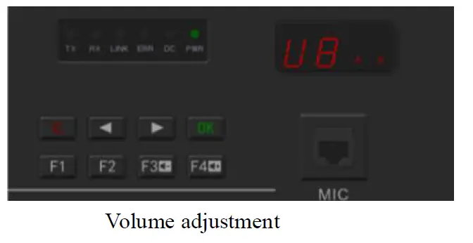
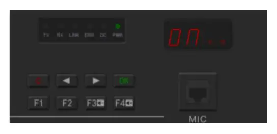
Monitor switch
- In the holding state, press to enter monitor switch menu, digital display “P1”, and then press “ ” to enter menu option, press , then enter monitor switch set up operation interface.
- Digital display “ON” or “OF” and shining, respectively represent turn on or turn off monitor switch.
- Press to confirm, digital display stop shining, the value will be saved and become effective when the next profession come, press to cancel the operation.

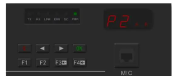
 Press again back to P1 menu interface. Power regulation In the P1 interface, press to enter power regulation menu option, digital display “P2”, back to P1 interface, press to enter power regulation set up operation interface, the process like below:
- The digital tube alternately display current power level L1 to L9 and current level power value, “L1” responding to 5W, “L9” responding to 45W, the picture below shows the current power level is level 6, the input power is 30W.
- Press or to decrease or increase the power level, digital tube alternately display new level “L1 to L9” and responding power value.
- Press to confirm, digital display stop shining, the value will be saved in the device, and become effective when the next profession comes, press to cancel the operation.
- Press to cancel the operation.
 Press again back to P1 menu interface. Power regulation In the P1 interface, press to enter power regulation menu option, digital display “P2”, back to P1 interface, press to enter power regulation set up operation interface, the process like below:
Password changing
In the P2 interface, press to enter password changing menu interface, the digital tube shows P3, you need verify old password before you change password, after the verification pass through, you can change the password, and the default factory password is “1 1 1 1 1 1”, the process like below: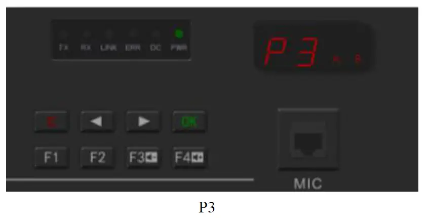
- Press P3 , firstly, password authentication, the digital tube shows and shining, the detailed process please refer to the “Password Authentication”
- After the password authentication pass, will have a tone mean you are correct, then you can start to set your new password.
- Press any combination of , set new six figures password, and then press to confirm.
- Repeat the up process, when these two times password are the same, the repeater will have a tone mean you are correct, the interface back to he P3 interface, mean the new password become effective, if the device have a warning alarm, which mean you are failed to set up a new password, please input the new password again.
- Press to cancel the operation and press again to back to the original interface.

Troubleshooting guide
| Description | Reason | Solution | ||||
| Boot problem | 1. | The power cord is in | 1. | Re-plug the | ||
| poor contact. | power cord | |||||
| 2. | The power cord is | 2. | Replace the | |||
| broken. | power cord | |||||
| 3. | The fuse of power | 3. | Replace the fuse | |||
| supply and insurance | 4. | Replace the | ||||
| board are broken. | switching power | |||||
| 4. | Switching power | supply | ||||
| supply failure | ||||||
| Write software connect | frequency failed to | 1. Control line is broken | 1. | Replace control line. | the | |
| Failed to set up a call | 1. Frequency of transmission and reception, colour code of transmission and reception, retuned code, are different from the handsets. 2. Channel parameter beyond the diplexer working bandwidth, equipment trouble light will be light, the speaker will warning alarm, the fault code is 12; 3. Receive module failed, the fault code is 30, 31,32. 4. Stimulus module failed, the fault code is 20,21,22. 5. Control panel failed, the fault code is 40,41,42. | 1. | Inspect channel | |||
| parameter: the | ||||||
| repeater high | ||||||
| frequency | ||||||
| transmit, low | ||||||
| frequency | ||||||
| receive: repeater | ||||||
| transmit | ||||||
| frequency is | ||||||
| corresponding to | ||||||
| the handsets’ | ||||||
| receive parts, | ||||||
| repeater’s | ||||||
| receive frequency | ||||||
| is corresponding | ||||||
| to the handsets’ | ||||||
| transmt | ||||||
| frequency, the | ||||||
| colour code and | ||||||
| retuned code is | ||||||
| the same with | ||||||
| handsets. | ||||||
| 2. | Change the | |||||
| channel | ||||||
| parameter in the | ||||||
| frequency of | ||||||
| diplexer work | ||||||
| range or change | ||||||
|
3.
4.
5. | the channel parameter frequency of the diplexer. Replace the receive module Replace the stimulus module Replace the control panel. | ||||
| Communication | 1. | Antenna head be | 1. | Examine the | |
| Distance | become | watered | antenna head, | ||
| shorter | 2. | Antenna is in poor | use the | ||
| connection | waterproof daub | ||||
| 3. | Frequency disruption | 2. | Replace the | ||
| 4. | Repeater transmit | antenna. | |||
| power decrease | 3. | Find out the | |||
| 5. | Receive module | frequency | |||
| sensitivity decrease | disrupted or | ||||
| change. | |||||
| 4. | Replace the | ||||
| power amplifier | |||||
| module. | |||||
| 5. | Replace the | ||||
| receive module. | |||||
| Indicator light no display, speaker no sound. | 1. 2. | Flat cable broken. The display board broken | 1.
2. | Replace the flat cable. Replace the display board. | |
When the repeater have some error, the error light will light up, the speaker will have a warning alarm, the digital tube will show the fault code. After the warning occur, firstly, check if the communication is OK, if don’t, restart the repeater, if still not work, please contact with the dealer around you.
The fault code as below:
| Alarm class | Alarm item | Fault condition | LED display code | sound |
|
RF power amplifier | 0.not detected RF power amplifier | I2C is blocked | 10 | |
| 1.E2PROM fault | I2C is blocked | 11 | ||
| 2.RF power amplifier fault | PA_ERRLED=1 | 12 | ||
| 3.RFpower amplifier overheat | PA_TEMPDEC ﹥ PA_CAP_TEMP | 13 | ||
| 4.RF power amplifier overflowing | PA_CURRENT ﹥ PA_CAP_CURRE NT | 14 | ||
| 5.RF power amplifier overvoltage | PA_VOLTAGE ﹥ PA_CAP_V_MAX | 15 | ||
| 6.RF power amplifier undervoltage | PA_VOLTAGE ﹤ PA_CAP_V_MIN | 16 | ||
| Stimulus module | 0.not detected stimulus module | I2C is blocked EX_PLLLD=0 | 20 | |
| 1.E2PROM fault | I2C is blocked | 21 | ||
| 2.Transmit frequency losing lock | RX-PLLLD=0 | 22 | ||
| Receive module | 0.not detected receive module | I2C is blocked EX_PLLLD=0 | 30 | |
| 1.E2PROM have problems | I2C is blocked | 31 | ||
| 2.receive frequency is locked. | RX-PLLLD=0 | 32 | ||
| Control panel | 0. Control panel have some problems | 40 | ||
| 1.E2PROM have problems | 41 | |||
| 2.Ditital module fault | HR500_RESET_I NT=0,SPI can not read | 42 | ||
| Channel parameter | 1. Transmit frequency is over | Stimulus module parameter, power | 01 |
| fault | range | amplifier module, duplexer parameter | ||||
| 2. | Receive frequency is over range | Receive parameter | module | 02 | ||
| 3. | Board-band, narrow-band | Stimulus module parameter, receive module parameter | 03 | |||
| 4. | Transmit power is over range | Power module, duplexer parameter | 04 | |||
FCC Compliance Notice
This device complies with part 15 of the FCC Rules. Operation is subject to the following two conditions:
- This device may not cause harmful interference, and
- this device must accept any interference received, including interference that may cause undesired operation. Any changes or modifications not expressly approved by the party responsible for compliance could void the user’s authority to operate the equipment. This equipment has been tested and found to comply with the limits for a Class B digital device, pursuant to part 15 of the FCC Rules. These limits are designed to provide reasonable protection against harmful interference in a residential installation. This equipment generates, uses and can radiate radio frequency energy and, if not installed and used in accordance with the instructions, may cause harmful interference to radio communications. However, there is no guarantee that interference will not occur in a particular installation. If this equipment does cause harmful interference to radio or television reception, which can be determined by turning the equipment off and on, the user is encouraged to try to correct the interference by one or more of the following measures:
- Reorient or relocate the receiving antenna.
- Increase the separation between the equipment and receiver.
- Connect the equipment into an outlet on a circuit different from that to which the receiver is connected.
- Consult the dealer or an experienced radio/TV technician for help.
- Operational Instructions and Training Guidelines To ensure optimal performance and compliance with the occupational/controlled environment RF energy exposure limits in the above standards and guidelines,users should always adhere to the following procedures: Antenna gain must not exceed 5dBi The antenna must be installed complying with the requirements of manufacturer or supplier, and it must be at least 110cm away from the human body.


