ADRF PSR-78-8527 700/800MHz Channelized Digital Repeater
Information in this document is subject to change without notice. Advanced RF Technologies, Inc. 1996-2020.
All rights reserved.
Please send comments to:
- E-Mail: [email protected]
- Phone: (818) 840-8131, (800) 313-9345
- Fax: (818) 840-8138
- Address: Advanced RF Technologies, Inc.
Attention: Technical Publications Department 3116 Vanowen St.
Burbank, CA 91505
USA
www.adrftech.com
INTRODUCTION
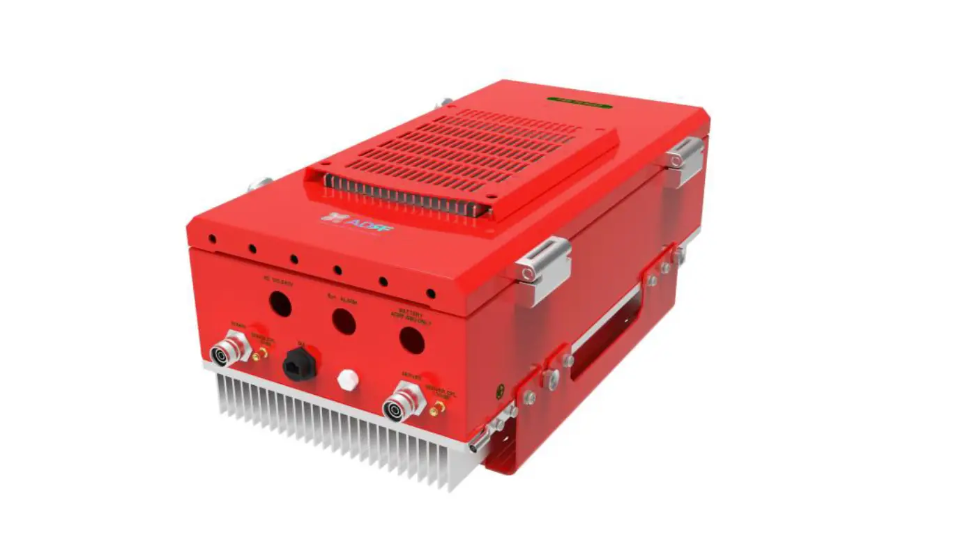
PSR-78-8527 bi-directional amplifiers (BDAs) extend the coverage area of radio communications in buildings and RF shadow environments.
Product Features
- Alarming output to supervised circuits for: antenna, amplifier, power supply, battery, and charger failure
- Up to 85dB of gain and up to 27 dBm downlink output power per band and up to 24 dBm uplink output power shared
- Software defined filtering of up to 2 non-contiguous wide band support
Highlights
- Supports both 700MHz and 800MHz Public Safety Frequencies in a single repeater
- Supports a total of 2 wideband non-contiguous channels per frequency band (700/800)
- Air convection cooling without fans
- Sharp Filter Roll-off performance (Wide: 60dBc @ Filter Bandwidth Edge + 1MHz)
- Web-based GUI Interface; No 3rd party GUI software required
- Web-GUI connectivity via DHCP in host mode
- External Alarm Function supporting dry contacts (10 outputs, 1 input)
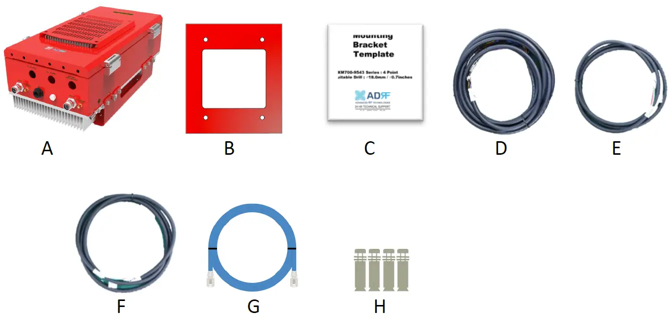
Parts List
| Label | Quantity | Description |
| A | 1 | PSR-78-8527 |
| B | 1 | Wall Mount Bracket |
| C | 1 | Mounting Bracket Template |
| D | 1 | AAI Alarm Cable |
| E | 1 | Battery Cable |
| F | 1 | AC Cable |
| G | 1 | Ethernet Cable (Crossover) |
| H | 4 | Anchor Bolt |
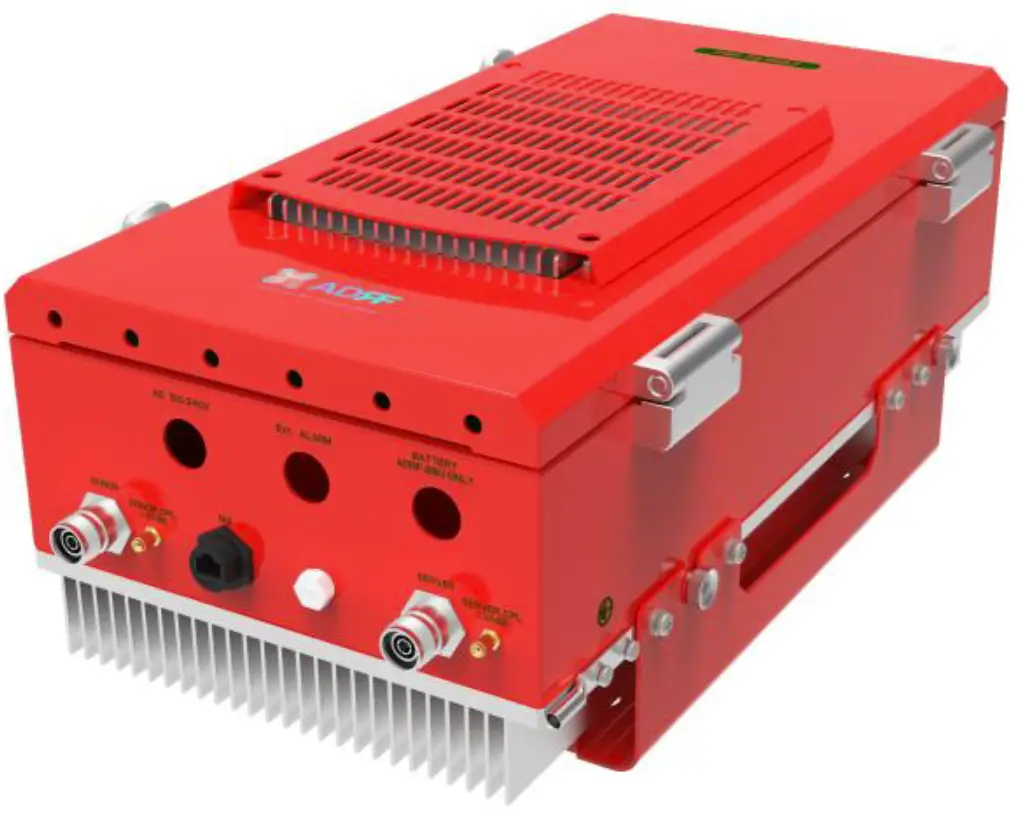
Quick View
 PSR-78-8527 External Ground Terminal
 PSR-78-8527 Quick View (Bottom)
Warnings and Hazards
WARNING! ELECTRIC SHOCK
Opening the PSR-78-8527 could result in electric shock and may cause severe injury.
WARNING! EXPOSURE TO RF
Working with the repeater while in operation, may expose the technician to RF electromagnetic fields that exceed FCC rules for human exposure. Visit the FCC website at www.fcc.gov/oet/rfsafety to learn more about the effects of exposure to RF electromagnetic fields.
WARNING! DAMAGE TO REPEATER
Operating the PSR-78-8527 with antennas in very close proximity facing each other could lead to severe damage to the repeater.
RF EXPOSURE & ANTENNA PLACEMENT Guidelines
Actual separation distance is determined upon gain of antenna used.
Please maintain a minimum safe distance of DL: 30 cm, UL: 70 cm while operating near the donor and the server antennas. Also, the donor antenna needs to be mounted outdoors on a permanent structure. In accordance with the FCC regulations, this device must meet 5W ERP requirements.
To satisfy this, the antenna cable name we propose is LMR200, If available and the antenna length must be at least of 6.8m (antenna cable loss at 6.8m is about 2 dBi). If you use another antenna cable, the cable loss must be considered to more than 2 dBi for UL. So, the maximum antenna gain after accounting for any cable losses should be up to UL: 14 dBi, Panel antenna.
WARRANTY
Opening or tampering the PSR-78-8527 will void all warranties.
Lithium Battery: CAUTION. RISK OF EXPLOSION IF BATTERY IS REPLACED BY INCORRECT TYPE. DISPOSE OF USED BATTERIES ACCORDING TO INSTRUCTIONS. CR2032 BATTERY MUST BE USED AS A REPLACEMENT ON THE CONTROL BOARD WHICH IS USED FOR REAL-TIME CLOCK (RTC) BACKUP.
Ethernet Instructions: This equipment is for indoor use only. All cabling should be limited to inside the building. Ethernet connection can only be used for programming/troubleshooting purposes only and is not to be connected during normal operation.
Preclude indications that Home/ personal use are prohibited.
Use of unauthorized antennas, cables, and/or coupling devices not conforming with ERP/EIRP is prohibited.
Regulatory Warning Statement
FCC RF Radiation Exposure Statement:
This equipment complies with FCC RF radiation exposure limits set forth for an uncontrolled environment. This equipment should be installed and operated with a minimum distance of
DL: 30 cm, UL: 70 cm between the radiator and your body. This transmitter must not be co-located or operating in conjunction with any other antenna or transmitter.
NOTE: This equipment has been tested and found to comply with the limits for a Class A digital device, pursuant to part 15 of the FCC Rules. These limits are designed to provide reasonable protection against harmful interference when the equipment is operated in a commercial environment. This equipment generates, uses, and can radiate radio frequency energy and, if not installed and used in accordance with the instruction manual, may cause harmful interference to radio communications. Operation of this equipment in a residential area is likely to cause harmful interference in which case the user will be required to correct the interference at their own expense.
FCC Part 90 Class B
WARNING. THIS is NOT a CONSUMER device. It is designed for installation by FCC LICENSEES and QUALIFIED INSTALLERS. You MUST have an FCC LICENSE or express consent of an FCC Licensee to operate this device. You MUST register Class B signal boosters (as defined in 47 CFR 90.219) online at www.fcc.gov/signal-boosters/registration. Unauthorized use may result in significant forfeiture penalties, including penalties in excess of $100,000 for each continuing violation.
FCC Part 15.21
Any changes or modifications not expressly approved by the party responsible for compliance could void the user’s authority to operate this equipment.
RSS-GEN, Sec. 7.1.2 – (transmitters)
Under Industry Canada regulations, this radio transmitter may only operate using an antenna of a type and maximum (or lesser) gain approved for the transmitter by Industry Canada. To reduce potential radio interference to other users, the antenna type and its gain should be so chosen that the equivalent isotopically radiated power (e.i.r.p.) is not more than that necessary for successful communication.
RSS-GEN, Sec. 7.1.2 – (detachable antennas)
This radio transmitter (identify the device by certification number, or model number if Category II) has been approved by Industry Canada to operate with the antenna types listed below with the maximum permissible gain and required antenna impedance for each antenna type indicated. Antenna types not included in this list, having a gain greater than the maximum gain indicated for that type, are strictly prohibited for use with this device.
RF Radiation Exposure
This equipment complies with RF radiation exposure limits set forth for an uncontrolled environment. This equipment should be installed and operated with a minimum distance of DL: 25 cm, UL: 60 cm between the radiator and your body. This transmitter must not be co-located or operating in conjunction with any other antenna or transmitter. RF exposure will be addressed at time of installation and the use of higher gain antennas require larger separation distances.
Maximum antenna gain after accounting for any cable losses should be up to UL: 14 dBi, Pannel antenna (antenna cable loss: more than 2dBi) to meet ERP 5W.
INSTALLATION
Cable Installation
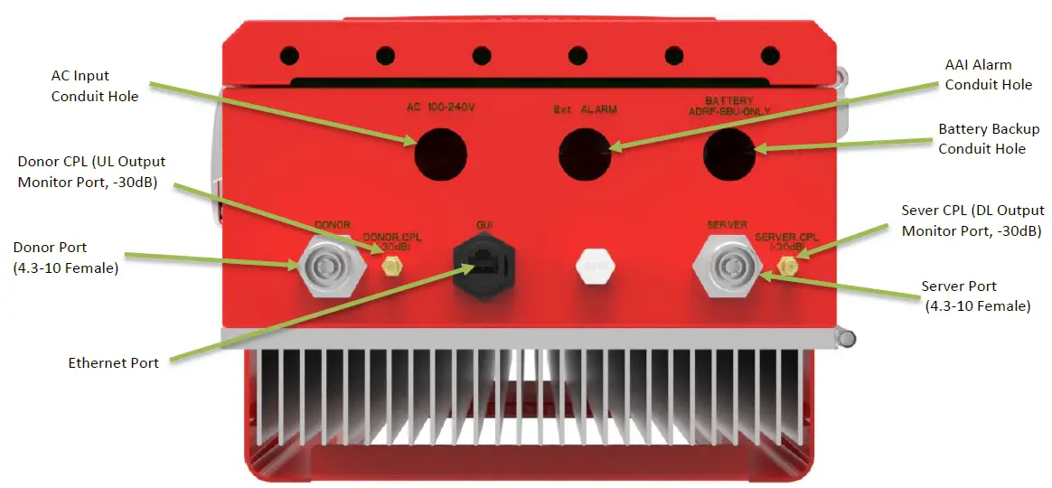
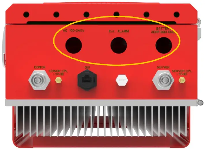
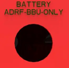
The bottom of the PSR-78-8527 has three conduit holes.
Conduit hole size and labels
| Silkscreen Label | Location | Diameter |
| AC 100-240V | LEFT | 22.2mm (7/8”) |
| Ext. ALARM | CENTER | 22.2mm (7/8”) |
| BATTERY ADRF-BBU ONLY | RIGHT | 22.2mm (7/8”) |
OVERVIEW
LED
PSR-78-8527 LED indicator lights are located on the inside of the repeater towards the bottom. Below the LED indicators is a button that is used to trigger the door open alarm.
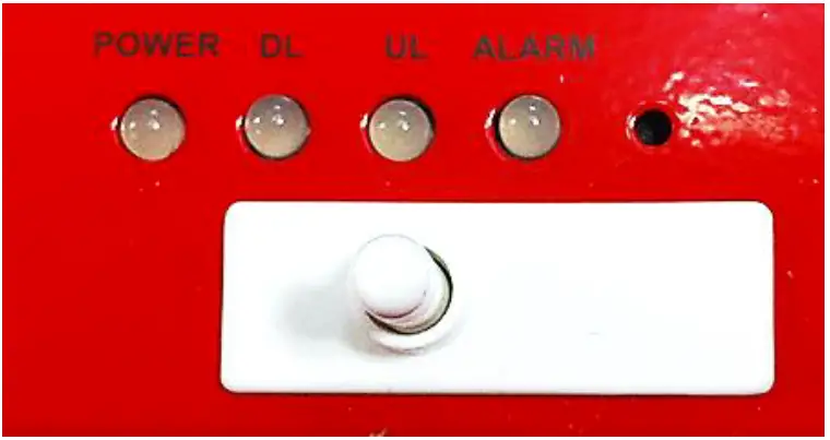
LED Specifications
| POWER | DL | UL | ALARM |
| AC Fail | DL Signal Not Detected | UL Out-Band Overload | Power-Related Alarms |
| DC Fail | DL Signal Low Detected | UL Input Overload | RF DL Path Related Alarms |
| Battery Fail | DL RF Power | UL Over Input | RF UL Path Related Alarms |
| Low Battery | DL Out-Band Overload | UL Over Power | Over Temperature |
| Battery Not Charge | DL Input Overload | UL Return Power | DSP Communication |
| Battery Not Connected | DL Over Input | UL PLL Fail | Door Open |
| Over Current | DL Over Power | System Halt | |
| DL Return Power | |||
| DL PLL Fail |
| LED Indicator | Specifications |
| Solid Green | Normal operation |
| Solid Yellow | Soft Fail alarm exists in the system |
| Solid Red | Hard Fail alarm exists in the system |
Cable Connection
AC Power
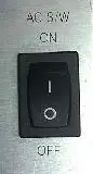
The AC Power on/off switch is on the left-hand of the PSU which is located inside of the repeater.
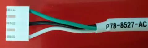 AC Connector
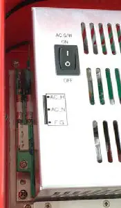
AC Terminal of the PSU
The AC terminal is at the left-hand side of the PSU. The repeater has a free-voltage range input of 100-240V AC. The AC connector of the AC cable must be connected to the AC terminal of the PSU, and the other end of the AC cable exits through the AC conduit hole and connects to AC power.
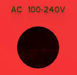 AC Cutout Hole (0.87 in)
External Alarm
 External Alarm Cutout Hole (0.87 in)
External Alarm port should be connected only to the fire alarm control panel. The default length of the cable that is provided to connect to an FACP is 6m (19.5ft). The EXT alarm wiring cannot exceed 30m (98.5ft).
External Alarm Description
| Color | Pin Description (24 pins) | ADRF External Alarm Box Pin Description | Alarm Type |
| Black | Donor antenna malfunction_P | 1-POS | Output |
| Black | Donor antenna malfunction_N | 1-NEG | Output |
| Brown | Active RF device malfunction_P | 2-POS | Output |
| Brown | Active RF device malfunction_N | 2-NEG | Output |
| Red | Low battery capacity (70%)_P | 3-POS | Output |
| Red | Low battery capacity (70%)_N | 3-NEG | Output |
| Orange | System component malfunction_P | 4-POS | Output |
| Orange | System component malfunction_N | 4-NEG | Output |
| Yellow | Normal AC Power_P | 5-POS | Output |
| Yellow | Normal AC Power_N | 5-NEG | Output |
| Green | Loss of normal AC Power_P | 6-POS | Output |
| Green | Loss of normal AC Power_N | 6-NEG | Output |
| Blue | Battery charger failure_P | 7-POS | Output |
| Blue | Battery charger failure_N | 7-NEG | Output |
| Purple | Summary Alarm_P | 8-POS | Output |
| Purple | Summary Alarm_N | 8-NEG | Output |
| Grey | Donor Antenna Disconnect_P | 9-POS | Output |
| Grey | Donor Antenna Disconnect_N | 9-NEG | Output |
| White | Oscillation Alarm_P | 10-POS | Output |
| White | Oscillation Alarm_N | 10-NEG | Output |
| Light Blue | Alarm-In | – | Input |
| Light Blue | GND(Alarm-In) | – | Input |
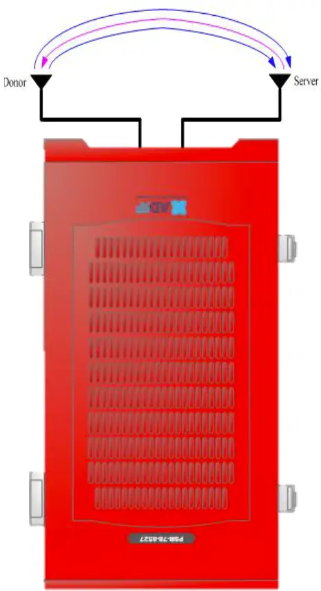
RF
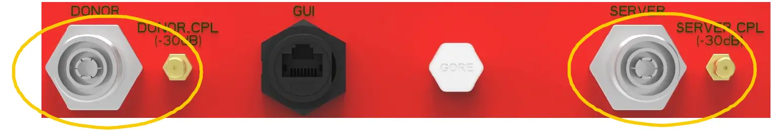
The RF connections are made via two 4.3-10 female connectors. The RF connector labeled “DONOR” must be connected to the antenna pointing towards the base station. The DONOR port can receive both 700 and 800MHz public safety signals. The RF connection labeled “SERVER” must be connected to the antenna facing the area to be covered by the BDA. The repeater has a single SERVER port that supports both 700 and 800MHz public safety signals.
The RF connections must be made using cables with an impedance of 50 ohms.
The separation between the antennas is necessary to prevent oscillation. Oscillation occurs when the signal entering the system continually re-enters, due to the lack of separation between the donor and server antennas. In other words, the signal is being fed back into the system. This creates a constant amplification of the same signal. As a result, the noise level rises above the signal level.
To prevent feedback, the donor and server antennas must be separated by an appropriate distance to provide sufficient isolation. Isolation is attained by separating antennas a sufficient distance so that the output of one antenna does not reach the input of the other. This distance is dependent on the gain of the repeater.
- DONOR – 4.3-10 female which is used to connect the donor antenna (700MHz + 800MHz PS)
- DONOR_CPL (30dB) – SMA female 30 dB coupling port which is used to monitor the output of UL signal
- SERVER_CPL (30dB) – SMA female 30 dB coupling port which is used to monitor the output of DL signal
- SERVER – 4.3-10 female which is used to connect the server antenna (700MHz + 800MHz PS)
Battery Backup Port
This port connects to the ADRF-BBS/BBL-24 (24V battery backup unit) via a dedicated cable provided by the ADRF.
 Battery Backup Cut-out hole (0.87 in)
When the ADRF-BBS/BBL-24 is connected to the repeater, the battery switch on the PSU must be switched to the ON position. This will enable the repeater to charge the ADRF-BBS/BBL-24 battery backup unit when AC power is present.
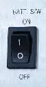 Battery Switch
Connect the ADRF-BBS/BBL-24 to the PSR-78-8527 via the external battery port to provide continuous power to the repeater during a power failure.
(WARNING: The circuit breaker switch on the ADRF-BBS/BBL-24 must be set to OFF before connecting it to the PSR-78-8527 to prevent damage to the repeater or the ADRF-BBS/BBL-24 and personal injury.)
Note: Please contact ADRF Technical Support for assistance if you are unfamiliar with the installation procedure of the battery box.
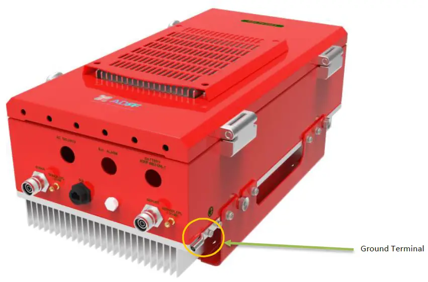
Grounding
The grounding terminal is located at the lower right-hand side of the BDA. A grounding cable should be properly connected before powering on the equipment.
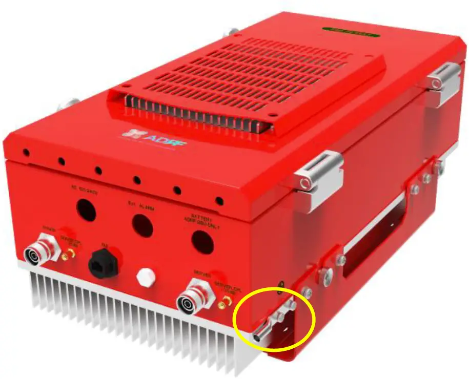 Ground Cable Terminal
Ground terminals located on the side of the repeater and can support a ground cable up to 1.25mm² (16AWG) in diameter and should be permanently connected to a grounding bar.
ALARMS
Message Board Alarms and Notifications
| Alarm | Alarm Description | Trigger Condition |
| AC Fail | AC Input is outside of operating range | The power supply is not operating within specs. |
| DC Fail | DC Output is outside of operating range | The power supply is not operating within specs. |
| Temperature | The module is above/below the normal operating temperature | The module is above the normal operating temperature. |
| Current | PSU is providing more than the max current | The power supply is not operating within specs. Over Current [ Above 10A] |
| System Halt | The system is in a shutdown state due to a hard fail alarm | The system is in a shutdown state due to a hard fail alarm. (10 cycles) |
| DSP Fault | The system has detected an issue with the internal DSP | The system has detected an issue with the DSP. |
| OSC | Oscillation detected | Oscillation detected. |
| DL Signal not detected | DL signal is below the specified level | DL signal is below the specified level. |
| DL Signal Low | DL signal is below the specified level | DL signal is below the specified level. |
| Input Overload | Incoming in-band DL or UL signal is too strong | Input signal is above the threshold. |
| Out of band Overload | Incoming out-band DL or UL signal is too strong | Out of band signal is above the threshold. |
| Synthesizer Lock Fail | There is an issue with the internal PLL | There is an issue with internal PLL. |
| DL RF Power | Input + gain does not match the output level (above delta of 6 dB) | Input + gain does not match the output level. |
| Overpower | The output level is above the max output levels | The output level is above the max output levels. |
| VSWR | Power is being reflected back to the repeater | Power is being reflected back to the repeater. |
| Reboot | Soft reboot performed | Reboot is performed from the Control tab. |
| Factory setting | Factory default settings restored | Factory setting is set from the Control tab. |
| Door | Door alarm set/clear | Door alarm set: Door open Door alarm clear: Door close |
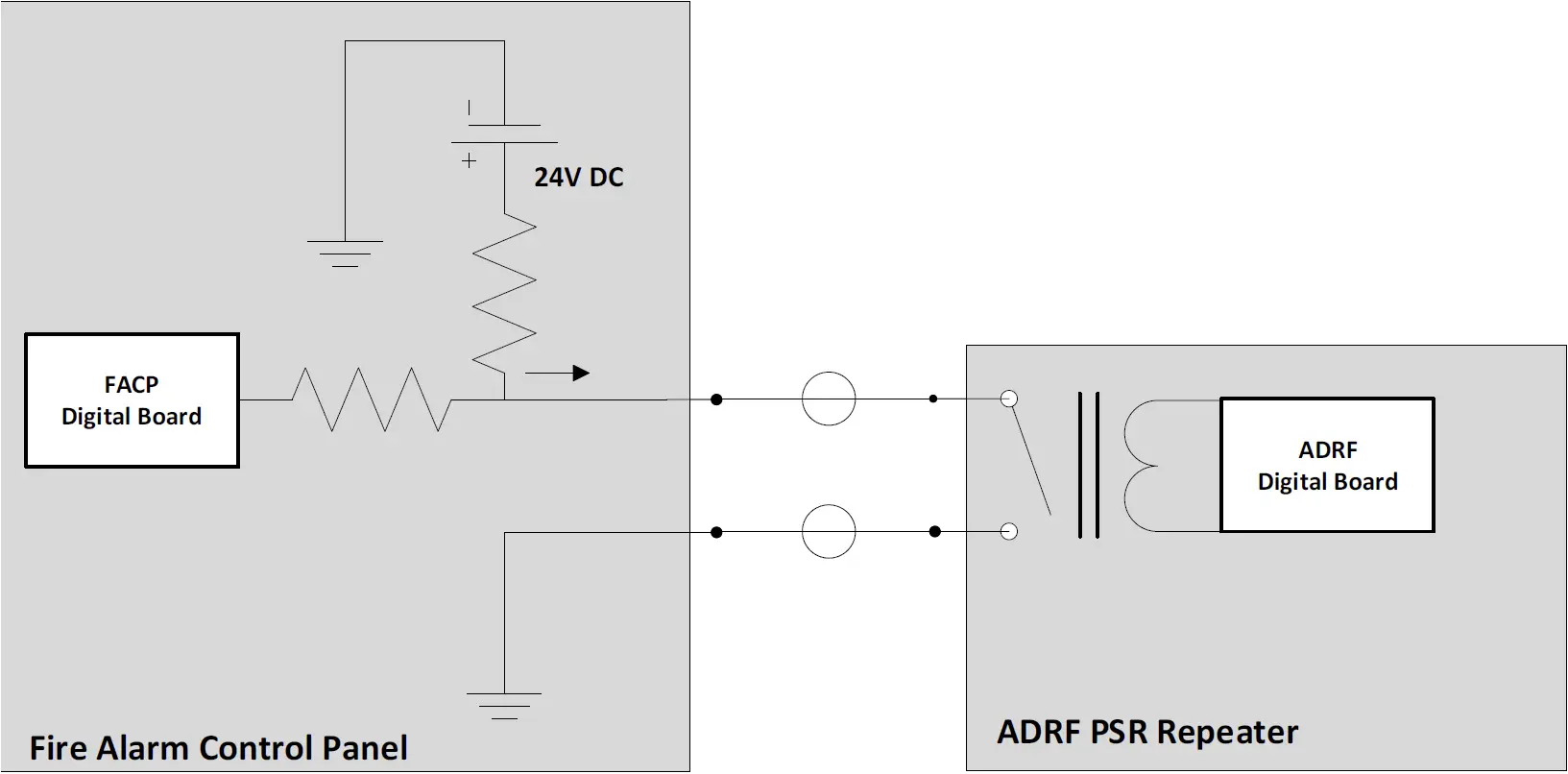
External Alarms
The PSR-78-8527 supports dry contact alarms and can be connected to a fire alarm control panel (FACP). The user can program the repeater to either create an open or closed circuit when an alarm is present in the system. The repeater must be installed within 30m (98.4ft) from the FACP.
External Alarm Output interface
| External Alarm Name | Set Condition | Likely Causes |
| Donor Antenna Malfunction |
|
|
| Active RF Device Malfunction |
|
|
| Low Battery Capacity (70% depleted) |
|
|
| System Component Malfunction |
|
|
| Normal AC Power |
|
|
| Loss of Normal AC Power |
|
|
| Battery Charger Failure |
|
|
| Summary Alarm |
|
|
| Donor Antenna Disconnect |
|
|
| Oscillation Alarm |
|
|
REPEATER INSTALLATION
Installation Procedures
Wall Mount Procedure
- Verify that the PSR-78-8527 and mounting holes are in good condition
- Place the PSR-78-8527 mounting bracket template up against the wall and mark off mounting holes
- Drill the appropriate size holes and install the included wall anchors
- Remove the wall mount bracket from the repeater and bolt the wall mount bracket to the wall
- Place the repeater onto the wall mount bracket and secure the bracket to the repeater
- Connect the GND cable
- Connect the Antenna cables
- Connect the Power cable
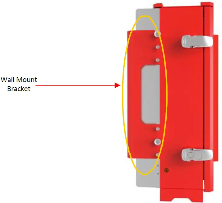 Wall Mount
Antenna Separation/Isolation
The separation between the donor and server antennas is necessary to prevent oscillation. Oscillation occurs when the signal entering the system continually re-enters, due to the lack of separation between the donor and server antennas. In other words, the signal is being fed back into the system. This creates a constant amplification of the same signal. As a result, the noise level rises above the signal level.
 RF Repeater Oscillation
To prevent feedback, the donor and server antennas must be separated by an appropriate distance to provide sufficient isolation. Isolation can be attained by separating antennas at a sufficient distance so that the output of one antenna does not reach the input of the other. This distance is dependent on the gain of the repeater.
Recommended isolation value is 15dB greater than the user-set gain of the repeater. For example, if the user-set gain of the repeater is 70dB, then isolation of 85dB or greater is required. In the same manner, to utilize the maximum gain of 85dB of the PSR-78-8527, antenna isolation of at least 100dB is required.
DO NOT APPLY AC POWER TO THE BDA UNTIL CABLES ARE CONNECTED TO BOTH PORTS OF THE BDA AND THE ANTENNAS.
- Prior to equipment use, the device must be registered with the FCC. This can be done through the FCC’s website at https://signalboosters.fcc.gov/signal-boosters
- To mount on a wall, use the appropriate screws and anchors to attach the BDA to the wall using the four mounting holes with the included wall mount bracket.
- Ensure that the isolation between the donor antenna and the serving antennas is at least 15 dB greater than the BDA gain.
- Connect the cable from the donor antenna to the BDA connector labeled “DONOR” and the cable from the serving antennas to the BDA connector labeled “SERVER”.
- Wire the AC power source to the AC terminal block inside of the wiring compartment of the BDA and secure the line using the appropriate conduit and conduit hub connectors.
- Power on the repeater by flipping the AC switch to the ON position located on the left side of the PSU.
- Installation of the BDA is now complete. Adjust the gain controls to suit the specific signal environment through the GUI on your PC.
MAINTENANCE GUIDE FOR PSR-78-8527 REPEATER
Periodic Inspection Checklist
- Repeater
- Log into the ADRF unit and check for any alarms in the system
- Address any outstanding alarms
- Check for loose connections to the repeaters/remotes and antennas. If connections are loose, make sure that all connections are tightly fastened.
- Check that cables and connectors are in good condition.
- Ensure that the repeater/remote brackets are in good condition and that the repeater/remote is securely fastened.
- Verify that the repeater has 3” of clearance on all sides to ensure proper ventilation.
Preventive Measures for Optimal Operation
Recommendations
Perform the Periodic Inspection Checklist on a semi-annually basis.
Precautions
- Do not operate the repeater with the antennas in extremely close proximity to one another as this may cause damage to the repeater.
- Do not change the parameters unless instructed to do so by an authorized supervisor.
- Do not move the repeater unless instructed to do so by an authorized supervisor.
- Do not detach any cables to the repeater unless repair of respective components is necessary.
WARRANTY AND REPAIR POLICY
General Warranty
The PSR-78-8527 carries a Standard Warranty period of two years unless indicated otherwise on the package or in the acknowledgment of the purchase order.
Limitations of Warranty
Your exclusive remedy for any defective product is limited to the repair or replacement of the defective product. Advanced RF Technologies, Inc. may elect which remedy or combination of remedies to provide in its sole discretion. Advanced RF Technologies, Inc. shall have a reasonable time after determining that a defective product exists to repair or replace the problem unit. Advanced RF Technologies, Inc. warranty applies to repaired or replaced products for the balance of the applicable period of the original warranty or ninety days from the date of shipment of a repaired or replaced product, whichever is longer.
Limitation of Damages
The liability for any defective product shall in no event exceed the purchase price for the defective product.
No Consequential Damages
Advanced RF Technologies, Inc. has no liability for general, consequential, incidental or special damages.
Additional Limitation on Warranty
Advanced RF Technologies, Inc. standard warranty does not cover products which have been received improperly packaged, altered, or physically damaged. For example, broken warranty seal, labels exhibiting tampering, physically abused enclosure, broken pins on connectors, any modifications made without Advanced RF Technologies, Inc. authorization, will void all warranty.
Return Material Authorization (RMA)
No product may be returned directly to Advanced RF Technologies, Inc. without first getting approval from Advanced RF Technologies, Inc. If it is determined that the product may be defective, you will be given an RMA number and instructions on how to return the product. An unauthorized return, i.e., one for which an RMA number has not been issued will be returned to you at your expense. Authorized returns are to be shipped to the address on the RMA in an approved shipping container. You will be given our courier information. It is suggested that the original box and packaging materials should be kept if an occasion arises where a defective product needs to be shipped back to Advanced RF Technologies, Inc. To request an RMA, please call (800) 313-9345 or send an email to [email protected].
SPECIFICATIONS
System Specifications
| Parameters | Specifications | Remarks | ||
| DL | UL | |||
| Frequency Range (MHz) | 700 | 758-768 (FCC & IC) 769-775 (FCC only) | 788-798 (FCC & IC) 799 -805 (FCC only) | |
| 800 | 851-861 (FCC only) | 806-816 (FCC only) | ||
| Composite Output Power | 27 dBm | 24 dBm | In case of 700/800 simultaneous output, the 3dB rule is adapted * Tolerance : +/-1 dB | |
| System Gain (dB) | 55-85 | 55-85 | * Tolerance : +/-1 dB | |
| Gain Control Range/Step(dB) | 30/0.5 | 30/0.5 | ||
| ALC range(dB) | 30 | 30 | ||
| Support of Filter BW | 2 non-contiguous Sub-band of 3/5/6/10/17/18(MHz) | |||
| Filter Roll-off | 60dBc@Filter Bandwidth Edge +1MHz | |||
| Squelch (UL) | -95~-80dBm in 5dB steps | |||
| Spurious | FCC meet | |||
| Passband Ripple | ±2 dB | |||
| Noise Figure @ Max gain | ≤7dB | |||
| System Group Delay | ≤7us | |||
| Power | 110 -240 VAC, 60 Hz (Free Voltage) | |||
| Power Consumption | <130W | |||
| No damage Max Input Power | +10dBm | |||
| Impedance | 50 Ohm | |||
| VSWR | <1.5:1 | |||
| Operating at Ambient Temperature | -22°F to +122°F (-30°C to +50°C) | |||
| Dimensions W x D x H | 10.13×7.56×19.7 in (257x192x500 mm) | w/o mount bracket | ||
| Weight | 35.7 lbs (16.2kg) | w/o mount bracket | ||
| RF Connector | 4.3-10 (Female, 2EA) : Donor Ant, Server Ant SMA (Female, 2EA) : -30dB Output Monitor | |||
| 1/2“ Liquid Tight Conduit Connector Hole | AC Line, Battery Line, External Alarm Line(AAI) | Hole size : 7/8” | ||
| Enclosure | IP66 | |||
MECHANICAL DRAWING
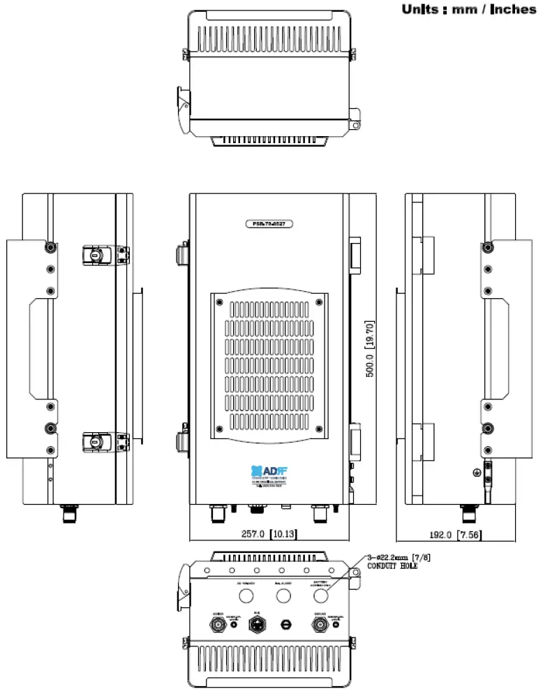 PSR-78-8527 Mechanical Drawing


