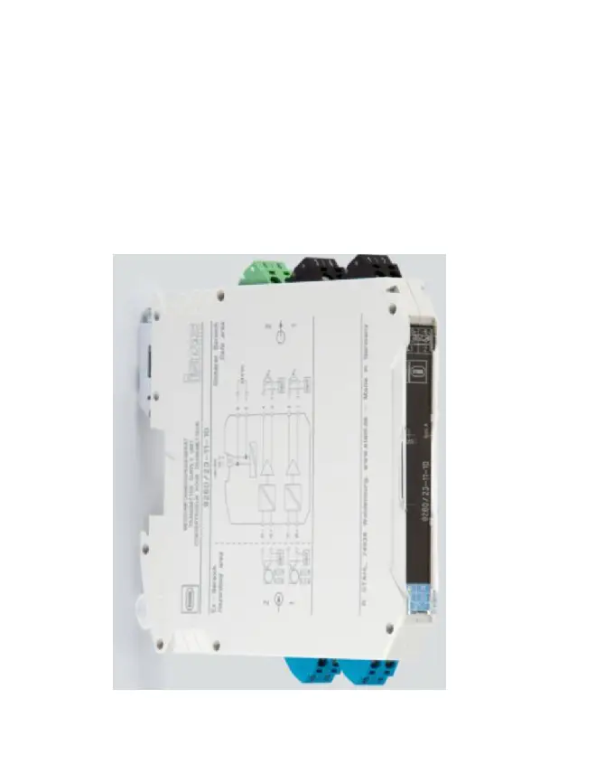
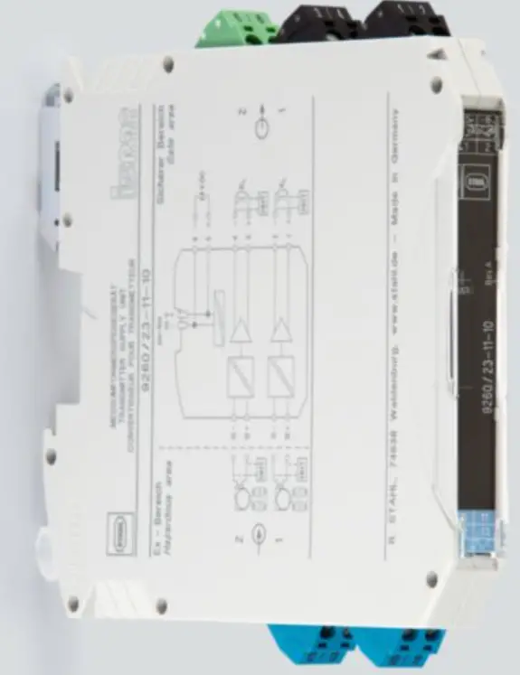
STAHL 261412 9270 Series Switching Repeater
Figures

Safety notes
Installation notes
- The device is an associated apparatus (category 1) which belongs to the “Intrinsic Safety” ignition protection class and can be installed in Ex zone 2 as a category 3 device. It meets the requirements of EN 60079- 0:2012+A11:2013, EN 60079-11:2012, EN 60079-15:2010 or IEC 60079-0 ed. 6.0, IEC 60079-11 ed. 6.0, and IEC 60079-15 ed. 4.0.
- Installation, operation, and maintenance may only be carried out by qualified electricians. Follow the installation instructions as described. When installing and operating the device, the applicable regulations and safety directives (including national safety directives), as well as general technical regulations, must be observed. For the safety data, refer to this document and the certificates (EU examination certificate and other approvals if appropriate).
- The device must not be opened or modified. Do not repair the device yourself, replace it with an equivalent device. Repairs may only be carried out by the manufacturer. The manufacturer is not liable for damage resulting from violation.
- The IP20 degree of protection (IEC/EN 60529) of the device is intended for use in a clean and dry environment (degree of pollution 2, IEC/EN 60664-1). Do not subject the device to mechanical and/or thermal loads that exceed the specified limits.
- The device complies with the EMC regulations for industrial areas (EMC class A). When using the device in residential areas, it may cause radio interference.
Intrinsic safety
- The device is approved for intrinsically safe (Ex i) circuits up to zone 0 (gas) and zone 20 (dust) in the Ex area. The safety technology values for intrinsically safe equipment and the connecting lines must be observed for the hook-up process (IEC/EC 60079-14) and the values specified in this installation note and/or the EU examination certificate must be observed.
- When carrying out measurements on the intrinsically safe side, observe the relevant regulations regarding the connection of intrinsically safe equipment. Use only these approved measuring devices in intrinsically safe circuits.
- If the device was used in circuits which are not intrinsically safe, it is forbidden to use it again in intrinsically safe circuits. Label the device clearly as being not intrinsically safe.
Installation in the Ex area (zone 2)
- Observe the specified conditions for use in potentially explosive areas! Install the device in a suitable, approved housing that meets the requirements of IEC/EN 60079-15 and has at least IP54 protection. Also observe the requirements of IEC/EN 60079-14.
- In zone 2 only connect or disconnect cables and adjust the DIP switch when the power is disconnected.
- In potentially explosive areas, only snap the device onto or off the pac-Bus 9294 or connect and disconnect the cables when the power is disconnected.
- The device must be stopped and immediately removed from the Ex area if it is damaged, was subject to an impermissible load, stored incorrectly or if it malfunctions.
Potentially dust-explosive areas
- The device is not suitable for installation in zone 22.
- If you nevertheless intend to use the device in zone 22, you must install it in a housing according to IEC/
EN 60079-31. Observe the maximum surface temperatures in this case. Adhere to the requirements of IEC/ EN 60079-14. - Connection to the intrinsically safe circuit in areas with a danger of dust explosions (zone 20, 21 or 22) is only permitted if the equipment connected to this circuit is approved for this zone (e.g., category 1D, 2D or 3D).
![]() NOTE
NOTE
When using the device in safety-related applications, observe the instructions in the safety manual available at r-stahl.com, as the requirements may differ for safety-related functions.
Short description
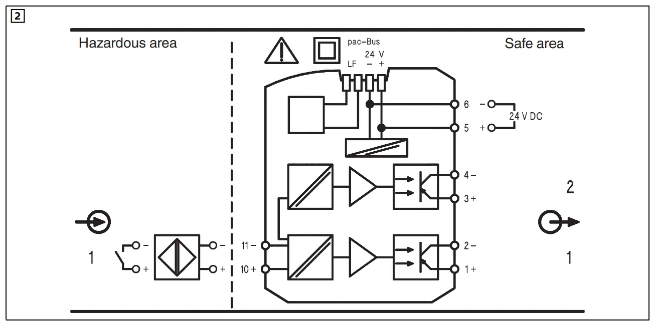
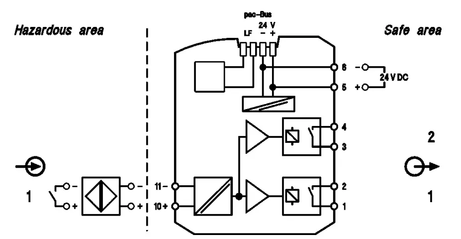
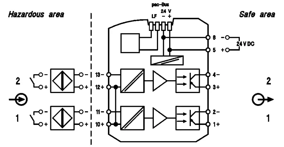
The switching repeater has been designed for intrinsically safe operation of proximity sensors (as per IEC/ EN 60947-5-6 NAMUR) and switch contacts with open circuit or resistance circuits, as well as switches, installed in hazardous zones. The output side has two passive transistors for transmitting the switching signal to the control level. Both these transistors can be operated as signal outputs. Output 2 can also be used as an error message output (set via the DIP switch).
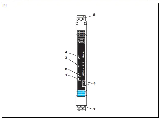
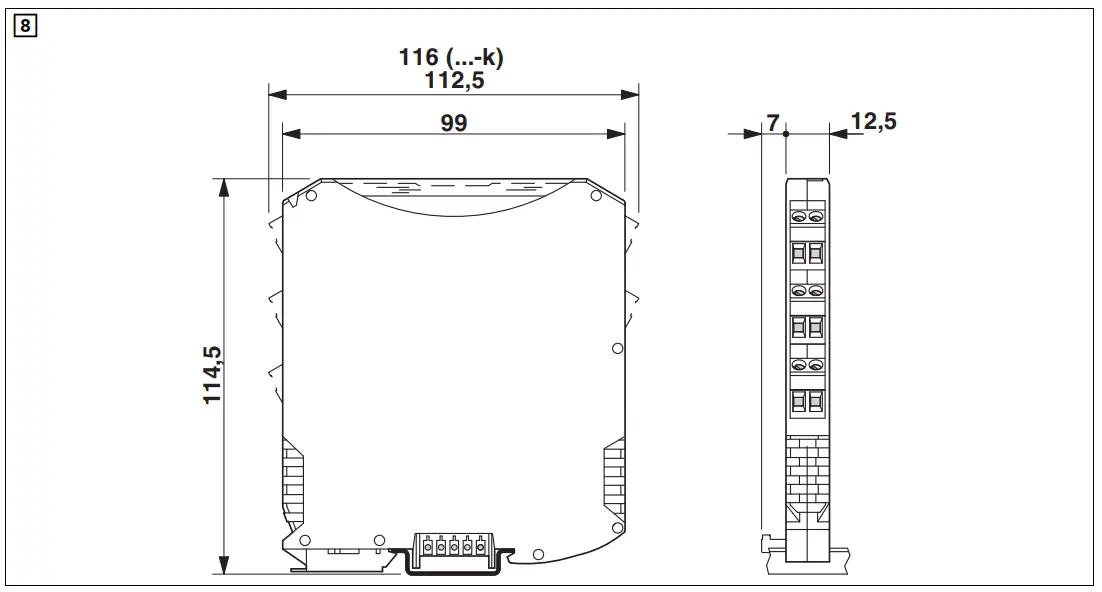
Operating and indicating elements [1]
- Yellow “OUT2” LED, status of transistor 2
- Yellow “OUT1” LED, status of transistor 1
- Red “LF” LED, line fault of the sensor cable
- Green “PWR” LED, power supply
- Connection terminal blocks for the safe area (black/green)
- Switch DIP 1 … DIP 4
- Connection terminal blocks for the Ex area (intrinsically safe Ex i, blue)
Installation
![]() NOTE: Electrostatic discharge Take protective measures against electrostatic discharge before opening the front cover!
NOTE: Electrostatic discharge Take protective measures against electrostatic discharge before opening the front cover!
Connection notes
EN / UL 61010-1:
WARNING
- Provide for a switch/circuit-breaker in the vicinity of a device that is marked as disconnect device for this device.
- Provide overcurrent protection (I ≤ 16 A) within the installation.
- To protect the device against mechanical or electrical damage, install it in suitable housing with an appropriate degree of protection according to IEC/EN 60529.
- During maintenance work, disconnect the device from all effective power sources.
- Before configuring settings using DIP switch, make sure the device has been de-energized.
- If the device is not used as described in the documentation, the intended protection can be negatively affected.
- Thanks to its housing, the device has basic insulation to the neighboring devices, for 300 Veff. If several devices are installed next to each other, this has to be taken into account, and additional insulation has to be installed if necessary! If the neighboring device is equipped with basic insulation, no additional insulation is necessary.
- The voltages present at the input, output and supply are extra-low voltages (ELV). Depending on the application, dangerous voltage (>30 V) against ground could occur. For this event, safe electrical isolation from the other connections has been implemented
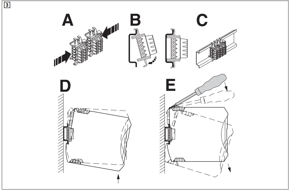
The device can be snapped onto all 35 mm DIN rails according to IEC/EN 60715. When using the 9294/31-12,
first insert it to bridge the power supply. ( ③ )
![]() NOTE
NOTE
Please also observe the direction of the module and pac-Bus 9294 when snapping into position: snap-on foot at the top and connector on the left.
Power supply
The supply voltage can be supplied via terminal points 5 and 6 or via the pac-Bus 9294.
Supply via terminal set 9194/50-01 You can connect the supply voltage directly with the bus connector by way of the terminal set. Adhere to the maximum feed-in of 4 A
Feed-in via supply module type 9193
Supply module type 9193 is used to feed in the supply voltage to the DIN rail bus connector.
Configuration
By default upon delivery, all DIP switches are in the “I” position. Position “I” = OFF, position “II” = ON
Direction of action (switch DIP 1)
I = Normal phase (operating current behavior)
II = Inverse phase (closed circuit current behavior)
Line fault detection (switch DIP 2)
I = Line fault detection disabled – (not permitted for safety-related applications)
II = Line fault detection enabled
In the event of a line fault, the transistor is disabled and the red LED (LF) flashes (NE 44).
The DIN rail bus connector is used to transmit an error message to the type 9193 supply module and to forward it as a group error message.
![]() NOTE
NOTE
For switch contacts with an open circuit, line fault detection (LF) must be disabled or the corresponding resistance circuit must be provided directly at the contact. (⑥)
Configuration of output 2 (switch DIP 3/4)
| DIP 3 | DIP 4 |
| I | I |
| I | II |
| II | I |
| II | II |
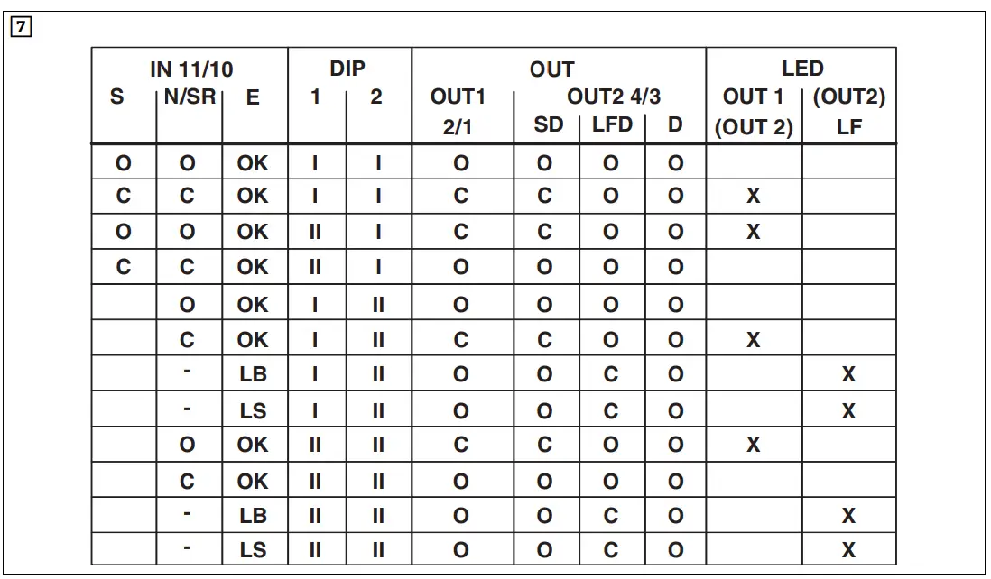
Truth table [7]
Key:
S: Switch without resistance circuit;
N: NAMUR sensor;
SR: Switch with resistance circuit; E: State of input circuit;
SD: Signal duplicator;
LFD: Fault indicator;
D: Disconnected;
O: Open/blocking;
C: Closed/conducting;
OK; LB: Open circuit;
LS: Short circuit
Technical data
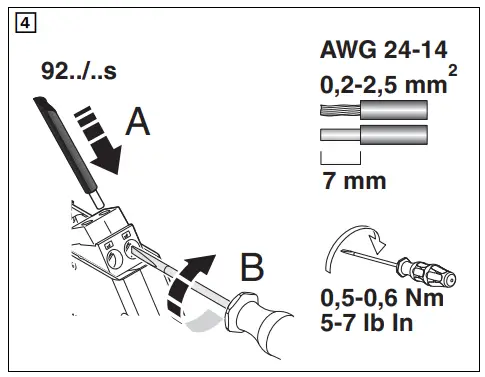
| Connection method | |
| Screw connection | |
| Hardware version | |
| Input signal NAMUR proximity sensors (IEC/EN 60947-5-6) Floating switch contacts Switch contacts with resistance circuit | Intrinsically safe |
| Switching points | Blocking conductive |
| Switching hysteresis | |
| Non-load voltage | |
| Line fault detection Break 0.05 mA < IIN < 0.35 mA Short circuit 100 Ω < RSensor < 360 Ω | |
| Output data | 2 transistor outputs, passive |
| Minimum switching voltage | |
| Maximum switching voltage | |
| Drop (ΔU) | |
| Min. switching current | short-circuit resistant |
| Max. switching current | short-circuit resistant |
| Switching frequency | |
| General data | |
| Nominal voltage UN | |
| Voltage range | 24 V DC -20%…+25% |
| Nominal current | 24 V DC |
| Power dissipation | |
| Ambient temperature Storage temperature | (Any mounting position) |
| Relative humidity | non-condensing |
| Fire resistance (UL 94) | |
| Electrical isolation | |
| Input/output Peak value in accordance with IEC/EN 60079-11 | |
| Input/supply, DIN rail connector Peak value in accordance with IEC/EN 60079-11 | |
| Input/output/supply, DIN rail connector Rated insulation voltage (overvoltage category II; pollution degree 2, safe isolation in accordance with IEC/EN 61010-1) 50 Hz, 1 min., test voltage | |
| Output 1/output 2 Rated insulation voltage (overvoltage category II; degree of pollution 2, basic insulation as per IEC/EN 61010-1) 50 Hz, 1 min., test voltage | |
| Safety data as per ATEX | |
| Max. output voltage Uo | |
| Max. output current Io | |
| Max. output current Io | |
| Max. output power Po | |
| Explosion group | Max. external inductivity Lo/Max. external capacitance Co |
| Max. internal inductance Li | negligible |
| Safety-related maximum voltage Um | |
| Conformance/Approvals | CE-compliant, additionally IEC/EN 61326 |
| ATEX | IBExU17ATEX1157X |
| IECEx | IECEx IBE 17.0046X |
| NEC | See final page |
| SIL in accordance with IEC 61508 | to |
| Noise immunity |
| Type and Terminal | Voc / Uo [Vdc] | Isc / Io [mA] | Po [mW] | Ci [nF] | Li [mH] | GP A,B or IIC | GP C or IIB | ||
| Ca / Co [nF] | La / L [mH] | Ca / Co [nF] | La / Lo [mH] | ||||||
| 9270/11 1*-1** No. 10, 11 9270/11-17-15* 9270/21-1*-14* No. 10, 11 / 12, 13 | 9.6 | 10 | 25 | 1.1 | Negligible | 510 840 1200 3600 | 100 5 1 0.01 | 2700 4400 630026000 | 100 5 1 0.01 |
Entity parameters for I.S. circuits:
| ||||||||||||||||||||||||||||||||||
Customer Support
R. STAHL Schaltgeräte GmbH
Am Bahnhof 30, 74638 Waldenburg, Germany
Tel: +49 7942 943-0 Fax: +49 7942 943-4333
Internet: r-stahl.com E-Mail: [email protected]