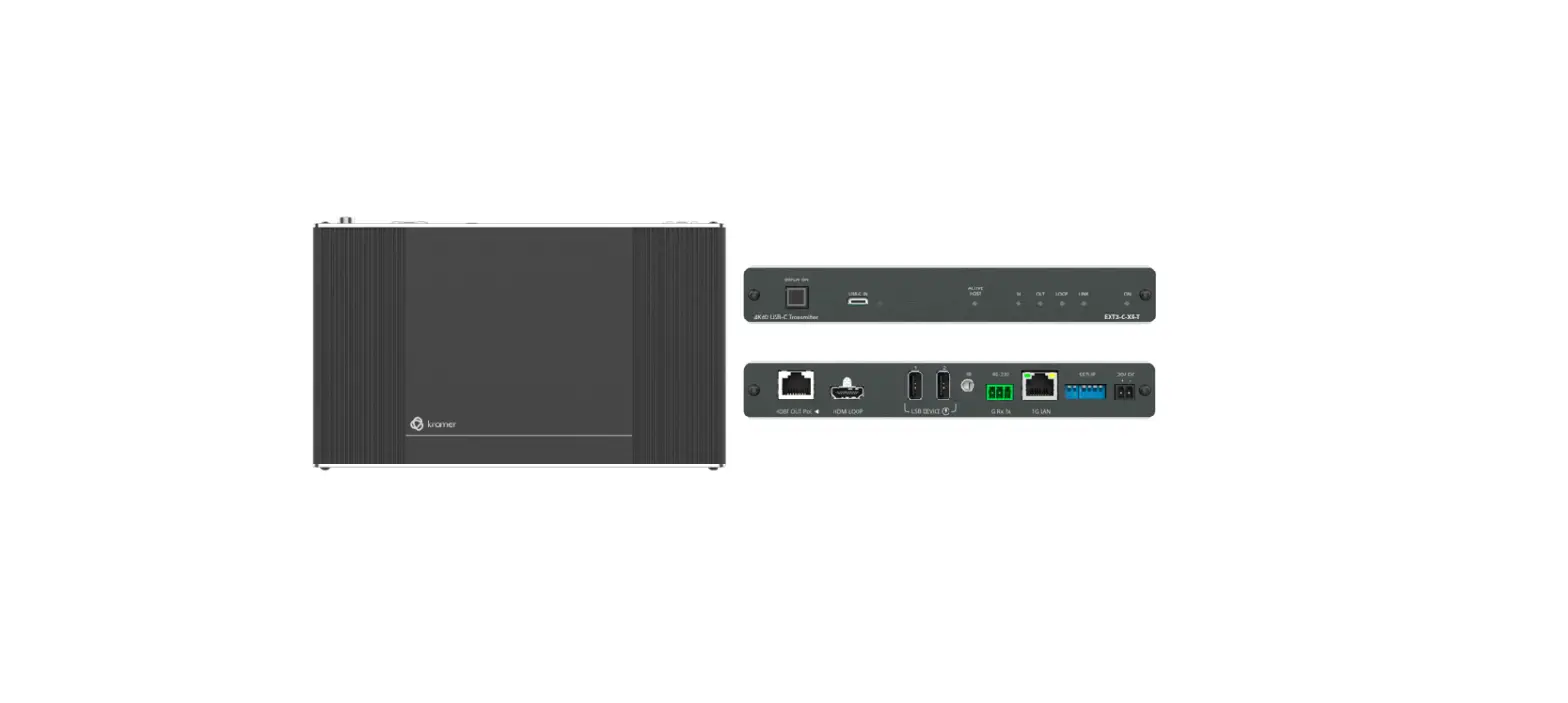
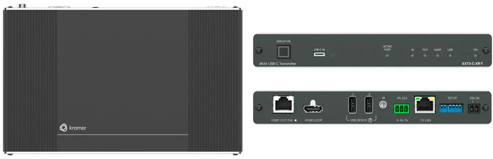
Kramer EXT3-C-XR-T 4K60 USB C Transmitter
This guide helps you install and use your EXT3-C-XR-T for the first time. Go to www.kramerav.com/downloads/EXT3-C-XR-T to download the latest user manual and check if firmware upgrades are available.
Scan for full manual

Check what’s in the box
- EXT3-C-XR-T 4K60 USB-C Transmitter
- 1 Bracket set
- 1 Quick start guide
- 1 Power adapter and cord
- 4 Rubber feet
- 1 Multi signal USB-C cable (1m)
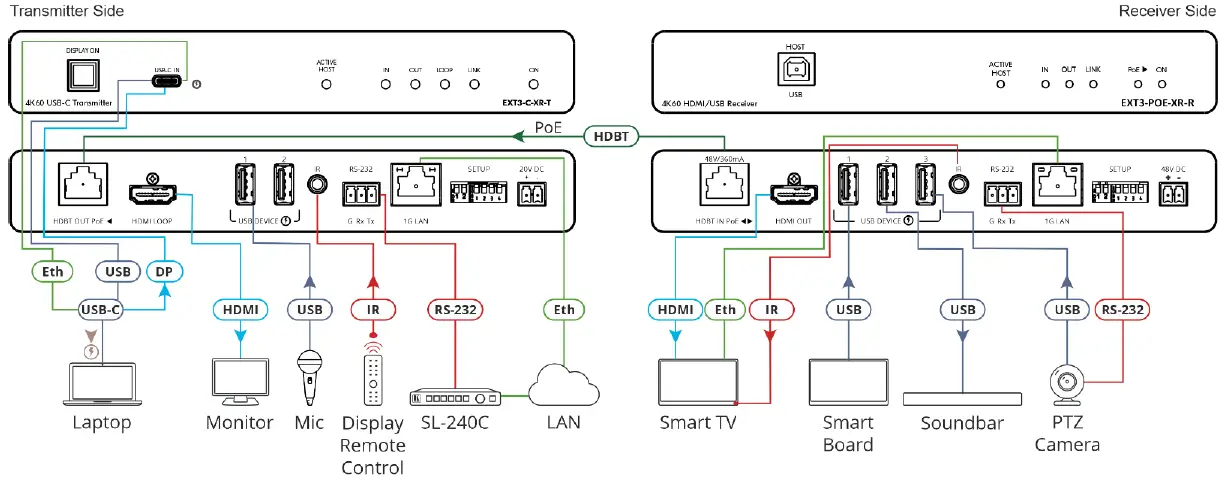
Get to know your EXT3-C-XR-T
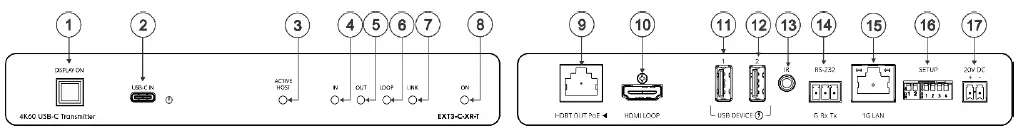
| # | Feature | Function |
| 1 | DISPLAY ON Button | Press to toggle power on/off the remote CEC-enabled display that is connected to the receiver side. Button LED lights blue when remote display power is on. |
| 2 | USB-C IN Connector | Connect to a USB-C AV source (that supports DisplayPort Alternate Mode) for AV input, USB host connection to local and remote connected USB devices (when the device DIP- switch is set to active host as defined in Step 4:Connect inputs and outputs), and LAN connection. Charges sources (that support USB Power Delivery 2.0) up to 60W when the device is powered via the power adapter). While charging, the charging icon (to the right of the connector) becomes visible and lights orange. Note: active host can be set only on one device, either the transmitter or the receiver, not both. |
| 3 | ACTIVE HOST LED | Lights orange when the USB host side is active. |
| 4 | IN LED | Lights blue when an active AV input signal is detected from the source device connected to the USB-C. |
| 5 | OUT LED | Lights blue when an HDMI output device is detected on the receiver side. |
| 6 | LOOP LED | Lights blue an active signal is transmitted on the HDMI LOOP port. |
| 7 | LINK LED | Lights green when the HDBT connection is active. |
| 8 | ON LED | Lights green when receiving power. |
| 9 | HDBT OUT PoE RJ-45 Connector | Connects to the HDBT IN RJ-45 connector on a receiver (for example, EXT3-POE-XR-R). Receives PoE (PD). |
| 10 | HDMI LOOP Connector | Connect to a local acceptor. |
| 11 | USB A 2.0 Charging Connector 1 | Connect to the USB local peripheral devices (for example, a USB PTZ camera). When USB Host PC is disconnected, the USB signal and charging power for this port are inactive. |
| 12 | USB A 2.0 Charging Connector 2 | Connect to the USB local peripheral devices (for example, a USB camera, a soundbar, microphone and so on). When USB Host PC is disconnected, the USB charging power for this port continues to be active. |
| 13 | IR 3.5mm Mini Jack | Bidirectional IR connection. Outputs a received IR signal (from the HDBT receiver) to connected IR emitter or transmits an IR signal (from IR sensor) to the HDBT receiver. |
| 14 | RS-232 3-pin Terminal Block | Connect to a controller device (for example, SL-240C) to control a remote device via serial connection (for example, the remotely connected PTZ USB camera). |
| 15 | 1G LAN RJ-45 Connector | Connect to a LAN for LAN-connection to the source device that is connected to the USB-C and Ethernet extension to the receiver. |
| 16 | SETUP 6-way DIP-switch | Sets the device behavior (see Step 4:Connect inputs and outputs). |
| 17 | 20V DC | +20V DC 6A connector for powering the unit and charging the connected input device to USB-C. |
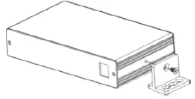
Mount EXT3-C-XR-T
Install EXT3-C-XR-T using one of the following methods:
- Attach the rubber feet and place the unit on a flat surface.
- Fasten a bracket (included) on each side of the unit and attach it to a flat surface
- Mount the unit in a rack using the recommended rack adapter
Warning
- Ensure that the environment (e.g., maximum ambient temperature & air flow) is compatible for the device.
- Avoid uneven mechanical loading.
- Appropriate consideration of equipment nameplate ratings should be used for avoiding overloading of the circuits.
- Reliable earthing of rack-mounted equipment should be maintained.
- Maximum mounting height for the device is 2 meters.
Connect inputs and outputs
Always switch OFF the power on each device before connecting it to your EXT3-C-XR-T.
This section defines the HDBT pinout, using a STRAIGHT pin-to-pin cable with RJ-45 connectors.
- It is recommended that the cable ground shielding be connected/soldered to the connector shield.
- To achieve specified extension distances, use the recommended Kramer cables available at www.kramerav.com/product/EXT3-C-XR-T.
- Using third-party cables may cause damage!
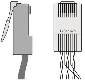
| EIA /TIA 568B | |
| PIN | Wire Color |
| 1 | Orange / White |
| 2 | Orange |
| 3 | Green / White |
| 4 | Blue |
| 5 | Blue / White |
| 6 | Green |
| 7 | Brown / White |
| 8 | Brown |
DIP-Switch Settings
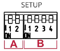
- The DIP-switches are used to set the HDBT range, upgrade the firmware, Determine IR signal pass-through.
- All the DIP-switches are set to OFF (up) by default.
A: DIP-switch Settings
| DIP # | Feature | DIP-1A | DIP-2A | State Description |
| 1A, 2A | HDBT Range Mode | Off | Off | Standard range mode. |
| Off | On | Ultra-long range mode. | ||
| On | Off | TBD | ||
| On | On | TBD |
B: DIP-switch Settings
- Changes to DIP-switches 2B and 3B only take effect after power cycling the device.
| DIP # | Feature | DIP-switch Settings |
| 1B | TBD | |
| 2B | Active USB Host | Off (default) – The device is configured as the host for connected USB devices. |
| On – USB are configured as slaves to the remote connection. | ||
| 3B | IR Modulation | Off (default) – IR pass-thru is enabled. |
| On – IR pass-thru is disabled (add a 38KHz modulation to the IR output signal). | ||
| 4B | RS-232 operation Mode | Off (default) – RS-232 FW programming is inactive (Normal operation mode is enabled). |
| On – RS-232 FW programming is active. |
Connect power
- Connect the power adaptor to theEXT3-C-XR-T and the power cord and plug it into the mains electricity.
Safety Instructions (See www.kramerav.com for updated safety information)
Caution: There are no operator-serviceable parts inside the unit.
Warning
- Use only the power cord that is supplied with the unit.
- Disconnect the power and unplug the unit from the wall before installing.
The terms HDMI, HDMI High-Definition Multimedia Interface, and the HDMI Logo are trademarks or registered trademarks of HDMI Licensing Administrator, Inc.


